EP1004971A2 - Peripheral apparatus, control method therefor and storage medium - Google Patents
Peripheral apparatus, control method therefor and storage medium Download PDFInfo
- Publication number
- EP1004971A2 EP1004971A2 EP99309389A EP99309389A EP1004971A2 EP 1004971 A2 EP1004971 A2 EP 1004971A2 EP 99309389 A EP99309389 A EP 99309389A EP 99309389 A EP99309389 A EP 99309389A EP 1004971 A2 EP1004971 A2 EP 1004971A2
- Authority
- EP
- European Patent Office
- Prior art keywords
- job
- attribute
- account
- user
- peripheral apparatus
- Prior art date
- Legal status (The legal status is an assumption and is not a legal conclusion. Google has not performed a legal analysis and makes no representation as to the accuracy of the status listed.)
- Ceased
Links
Images


Classifications
-
- G—PHYSICS
- G06—COMPUTING; CALCULATING OR COUNTING
- G06Q—INFORMATION AND COMMUNICATION TECHNOLOGY [ICT] SPECIALLY ADAPTED FOR ADMINISTRATIVE, COMMERCIAL, FINANCIAL, MANAGERIAL OR SUPERVISORY PURPOSES; SYSTEMS OR METHODS SPECIALLY ADAPTED FOR ADMINISTRATIVE, COMMERCIAL, FINANCIAL, MANAGERIAL OR SUPERVISORY PURPOSES, NOT OTHERWISE PROVIDED FOR
- G06Q99/00—Subject matter not provided for in other groups of this subclass
Definitions
- the present invention relates to a peripheral apparatus such as a printer, scanner, copy machine and facsimile having an account function, to its control method and to a storage medium for realizing such a method.
- a conventional printer is not provided with means for confirming whether a job can be executed without fail before it is issued. Therefore, unless a job is actually issued, whether or not the job is executed without fail cannot be confirmed.
- the invention provides a peripheral apparatus for making each function means execute a job in response to a job request from a client, comprising: means for storing an account limit value of the client; means for judging whether an account value corresponding to the job request from the client reaches the account limit value; and means for regulating a transmission of the job by the client in accordance with a judgement result by the judging means.
- Another embodiment of the invention provides a peripheral apparatus comprising: setting means for setting an account identification code corresponding to each of a plurality of user identification codes; detecting means for analyzing a user identification code added to a transmitted job and detecting a corresponding account code; and accounting means for charging a client corresponding to the account identification code for the job.
- Another embodiment of the invention provides a peripheral apparatus capable of registering, storing and deleting a plurality of user identification codes and account identification codes and account counters corresponding to the user identification codes and the account identification codes, comprising: means for registering, storing and deleting a relation of user IDs belonging to each account identification code; means for analyzing the user ID added to a transmitted job; and accounting means for executing a charging operation relative to a counter corresponding to the account ID to which the user ID added to the job belongs.
- Another embodiment of the invention provides a peripheral apparatus capable of registering, storing and deleting a plurality of account IDs and corresponding account counters, comprising: means for analyzing a user ID and an account ID added to a transmitted job; means for determining which of the user ID and the account ID is charged; and means for charging the account counter corresponding to the determined user ID or the determined account ID.
- Another embodiment of the invention provides a peripheral apparatus connected via a network to an information apparatus, wherein the peripheral apparatus comprises control means for controlling a plurality of function means and accounting means for charging for a use of the function means; and the charging means charges for a user and/or a client identified by a user identification code and/or an account identification code supplied from the information processing apparatus.
- Another embodiment of the invention provides a method of controlling a peripheral apparatus capable of registering, storing and deleting a plurality of user identification codes and account identification codes and account counters corresponding to the user identification codes and the account identification codes, comprising the steps of: analyzing the user ID added to a transmitted job; and executing a charging operation relative to a counter corresponding to the account ID to which the user ID added to the job belongs.
- Another embodiment of the invention provides a computer readable storage medium storing a control program for a peripheral apparatus capable of registering, storing and deleting a plurality of user identification codes and account identification codes and account counters corresponding to the user identification codes and the account identification codes, the control program comprising the steps of: analyzing the user ID added to a transmitted job; and executing a charging operation relative to a counter corresponding to the account ID to which the user ID added to the job belongs.
- Another embodiment of the invention provides an accounting apparatus comprising: setting means for setting a relation between a user identification code, an account identification code and a service identification code; and charging means for charging an account counter corresponding to one of the identification codes for a job.
- Fig. 1 is a diagram showing the structure of a multi-function peripheral apparatus (MFP) according to an embodiment of the invention.
- MFP multi-function peripheral apparatus
- Fig. 2 is a diagram showing the system structure according to an embodiment of the invention.
- Fig. 3 is a diagram showing the hardware structure of a controller of MFP shown in Fig. 1.
- Fig. 4 is a diagram showing the software structure of a controller of MFP shown in Fig. 1.
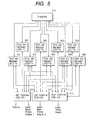
- Fig. 5 is a diagram showing the software structure of a controller of MFP shown in Fig. 1.
- Fig. 6 is a diagram showing the software structure of a controller of MFP shown in Fig. 1.
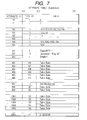
- Fig. 7 is an attribute table of a supervisor 410 shown in Fig. 4.
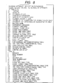
- Fig. 8 is a diagram explaining the meanings of an attribute ID and a type ID of the attribute table shown in Fig. 7.
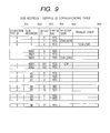
- Fig. 9 is a sub address - service ID corresponding table.
- Fig. 10 is a diagram explaining the meanings of a connection type ID shown in Fig. 9.
- Fig. 11 is a sub address - task type corresponding table.
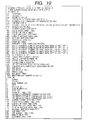
- Fig. 12 is a diagram explaining the meanings of a task type ID shown in Fig. 11.
- Fig. 13 is a user certification table.
- Fig. 14 is an access control table.
- Fig. 15 is a diagram explaining a security level.
- Fig. 16 is an event set table.
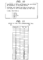
- Fig. 17 is an event format table.
- Fig. 18 is an attribute table of a print manager.
- Fig. 19 is a diagram explaining the meanings of an attribute ID and a type ID in the attribute table shown in Fig. 18.
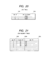
- Fig. 20 is a job table.
- Fig. 21 is a job request table.
- Fig. 22 is an attribute table of a scan job manager.
- Fig. 23 is a diagram explaining the meanings of an attribute ID and a type ID in the attribute table shown in Fig. 22.
- Fig. 24 is an attribute table of a copy job manager.
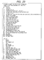
- Fig. 25 is a diagram explaining the meanings of an attribute ID and a type ID in the attribute table shown in Fig. 24.
- Fig. 26 is an attribute table of a font manager.
- Fig. 27 is a diagram explaining the meanings of an attribute ID and a type ID in the attribute table shown in Fig. 26.
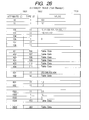
- Fig. 28 is a font table.
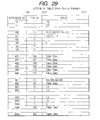
- Fig. 29 is an attribute table of a form overlay manager.
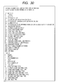
- Fig. 30 is a diagram explaining the meanings of an attribute ID and a type ID in the attribute table shown in Fig. 29.
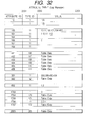
- Fig. 31 is a form overlay table.
- Fig. 32 is an attribute table of a log manager.
- Fig. 33 is a diagram explaining the meanings of an attribute ID and a type ID in the attribute table shown in Fig. 32.
- Fig. 34 is a log table.
- Fig. 35 is a diagram explaining the contents of log data.
- Fig. 36 is a log format table.
- Fig. 37 is an attribute table of a color profile manager.
- Fig. 38 is a diagram explaining the meanings of an attribute ID and a type ID in the attribute table shown in Fig. 37.
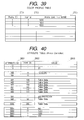
- Fig. 39 is a color profile table.
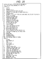
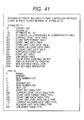
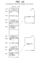
- Fig. 40 is an attribute table of a printer controller.
- Fig. 41 is a diagram explaining the meanings of an attribute ID and a type ID in the attribute table shown in Fig. 40.
- Fig. 42 is a job queue table.
- Fig. 43 is a diagram explaining the meanings of statuses shown in Fig. 42.
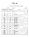
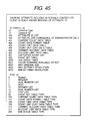
- Fig. 44 is an attribute table of a scanner controller.
- Fig. 45 is a diagram explaining the meanings of an attribute ID and a type ID in the attribute table shown in Fig. 44.
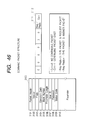
- Fig. 46 shows the format of a command packet.
- Fig. 47 is a flow chart illustrating a command packet process.
- Fig. 48 is a flow chart illustrating an attribute table access process.
- Fig. 49 is a flow chart illustrating a service ID list inquiry process.
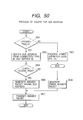
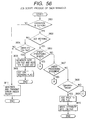
- Fig. 50 is a flow chart illustrating a service address inquiry process.
- Fig. 51 is a flow chart illustrating a process of inquiring a service ID by designating a task type.
- Fig. 52 is a diagram illustrating certification of a service ID, a user ID and a PWD.
- Fig. 53 is a diagram showing the structure of jobs.
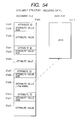
- Fig. 54 is a diagram showing the structure of documents.
- Fig. 55 is a diagram showing the structure of binders.
- Fig. 56 is a flow chart illustrating a job script process to be executed by each manager.
- Fig. 57 is a diagram illustrating a job script process to be executed by a manager.
- Fig. 58 is a diagram illustrating a job script process to be executed by a manager.
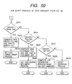
- Fig. 59 is a diagram illustrating a job script process to be executed by a manager.
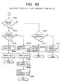
- Fig. 60 is a diagram illustrating a job script process to be executed by a manager.
- Fig. 61 is a diagram illustrating a job script process to be executed by a manager.
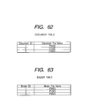
- Fig. 62 is a document table.
- Fig. 63 is a binder table.
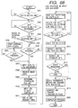
- Fig. 64 is a flow chart illustrating a job process to be executed by a print job manager.
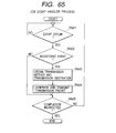
- Fig. 65 is a flow chart illustrating a job event handler process.
- Fig. 66 is a flow chart illustrating a data reception - PDL rasterizer process.
- Fig. 67 is a flow chart illustrating a printer controller process.
- Fig. 68 is a flow chart illustrating an account process.
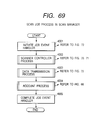
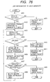
- Fig. 69 is a flow chart illustrating a job process to be executed by a scan job manager.
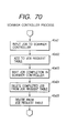
- Fig. 70 is a flow chart illustrating a scanner controller process.
- Fig. 71 is a flow chart illustrating a scanner controller internal process.
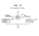
- Fig. 72 is a flow chart illustrating a data transmission process.
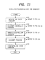
- Fig. 73 is a flow chart illustrating a job process in a copy job manager.
- Fig. 74 is a flow chart illustrating a job process (download) to be executed by a font manager, a form overlay manager, a log manager, and a color profile manager.
- Fig. 75 is a flow chart illustrating a job process (upload) to be executed by a font manager, a form overlay manager, a log manager, and a color profile manager.
- Fig. 76 is a flow chart illustrating a job management at each manager.
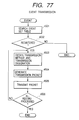
- Fig. 77 is a flow chart illustrating an event transmission process.
- Fig. 78 is a flow chart illustrating a process of transmitting data (script) from a device.
- Fig. 79 is a diagram showing the hardware structure of a client PC.
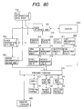
- Fig. 80 is a diagram showing the software (control program) structure of a client PC.
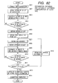
- Fig. 81 is a flow chart illustrating a packet generation/transmission process.
- Fig. 82 is a flow chart illustrating a process of acquiring information at a client side and automatically configuring software (control program).
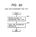
- Fig. 83 is a flow chart illustrating a process of issuing a job by designating a task type.
- Fig. 84 is a diagram showing the structure of an event.
- Fig. 85 is a flow chart illustrating an event transmission process.
- Fig. 86 is a flow chart illustrating a log process.
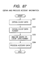
- Fig. 87 is a flow chart illustrating a process of acquiring and processing account information.
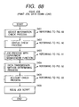
- Fig. 88 is a flow chart illustrating a process of issuing a job (print job, data download).
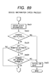
- Fig. 89 is a flow chart illustrating a device information check process.
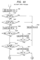
- Fig. 90 is a diagram illustrating a status check process before job issue.
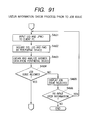
- Fig. 91 is a flow chart illustrating a job process with a user management function.
- Fig. 92 is a flow chart illustrating a data transmission method determining process.
- Fig. 93 is a diagram illustrating an account check process.
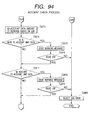
- Fig. 94 is a diagram illustrating an account check process.
- Fig. 95 is a diagram showing an error message.
- Fig. 96 is a diagram showing an error message.
- Fig. 97 is a diagram showing an error message.
- Fig. 98 is a diagram showing an error message.
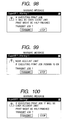
- Fig. 99 is a diagram showing an error message.
- Fig. 100 is a diagram showing an error message.
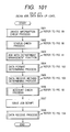
- Fig. 101 is a flow chart illustrating a process of issuing a job (scan job, data upload).
- Fig. 102 is a flow chart illustrating a data type determining process.
- Fig. 103 is a flow chart illustrating a data reception method determining process.
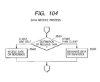
- Fig. 104 is a flow chart illustrating a data reception process.
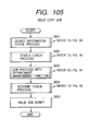
- Fig. 105 is a flow chart illustrating a copy job issue process.
- Fig. 106 is a flow chart illustrating a job management command issue process.
- Fig. 107 is a memory map of a disk 315 of MFP.
- Fig. 108 is a memory map of a disk 6009 of a client PC.
- Fig. 109 is a diagram showing the structure of a client PC.
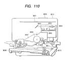
- Fig. 110 is a diagram showing an LBP applicable to a laser beam printer of MFP.
- Fig. 111 is a diagram showing an IJRA applicable to an ink jet printer of MFP.
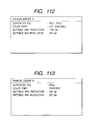
- Fig. 112 is a diagram showing an example of a screen displayed on a display.
- Fig. 113 is a diagram showing an example of a screen displayed on a display.
- Fig. 114 is an account ID table.
- Fig. 115 is a current count data table.
- Fig. 116 is a count data format table.
- Fig. 117 is a count limit data table.
- Fig. 118 is a count unit price data table.
- Fig. 119 is a current account data table.
- Fig. 120 is an account limit data table.
- Fig. 121 is a diagram showing the structure of a two-layer job script.
- Fig. 122 is a diagram showing the structure of a three-layer job script.
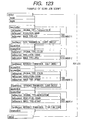
- Fig. 123 is a diagram showing the structure of a scan job script.
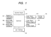
- Fig. 1 is a diagram showing the structure of a multi-function peripheral (MFP) according to an embodiment of the invention.
- MFP multi-function peripheral
- the multi-function peripheral is connected to various types of network devices to be described below, and collectively manages and controls respective devices in response to an instruction supplied from a client via a network.
- reference numeral 101 represents a controller for controlling MFP.
- This controller 101 is constituted of a hardware structure shown in Fig. 3 and a software structure (control/management programs) such as a program shown in Fig. 106 which is stored in a disk 315 shown in Fig. 3.
- the controller 101 controls and manages the network devices.
- Reference numeral 102 represents a scanner engine which is controlled by the controller 101.
- Reference numerals 103 and 104 represent laser printer engines (LBP) 1, 2 which are controlled by the controller 101.
- LBP laser printer engines
- the laser printer engine 1 indicated at reference numeral 103 is connected to a finisher 106 which can collect a plurality of recording materials (such as paper) output from the printer engine and staple them.
- the finisher 106 is also controlled by the controller 101.
- Reference numeral 105 represents an ink jet printer engine (IJP) which can print out a color print and is controlled by the controller 101.
- Reference numeral 107 represents a network (Ethernet) interface which provides the controller 101 with bidirectional communications.
- Reference numeral 108 represents an IEEE 1394 interface which provides the controller 101 with bidirectional communications.
- Reference numeral 109 represents an IEEE 1284 interface which provides the controller 101 with bidirectional communications.
- Reference numeral 110 represents a user interface which is constituted of an LCD display and a keyboard which are used to display information supplied from the controller 101 and transfers a user instruction to the controller 101.
- MFP constructed as above manages and controls the devices including three physical printers LBP (B/W, with finisher) 103, LBP (B/W) 104 and IJP (color) 105.
- MFP can issue a print job selectively to these physical printers.
- MFP can also control four logical printers (cluster printers) by reconfiguring these physical printers, the logical printers including LBP 103 + LBP 104, LBP 104 + IJP 105, LBP 103 + IJP 105, and LBP 103 + LBP 104 + IJP 105. Similar to the physical printers, MFP can issue a print job selectively to these logical printers.
- IJP may be reconfigured to a logical printer capable of printing out only a B/W print and MFP can also issue a print job to this logical printer.
- These seven printers, LBP 103, LBP 04, IJP 105, LBP 103 + LBP 104, LBP 104 + IJP 105, LBP 103 + IJP 105, and LBP 103 + LBP 104 + IJP 105 can be automatically selected in response to a print job instructed by a client and the print job is executed by using optimum printers.
- a color original can be read with a scanner in response to a scan job issued from a client.
- a copy job can be issued by selecting (or automatically selecting) the scanner and the eight printers LBP 103, LBP 04, IJP 105, LBP 103 + LBP 104, LBP 104 + IJP 105, LBP 103 + IJP 105, LBP 103 + LBP 104 + IJP 105, and IJP capable of only a B/W printer. If the printer is only IJP, a color copy job can also be issued.
- Fonts and form overlays prepared in advance can be used in a print job. These fonts and form overlays can be uploaded and downloaded between devices or to and from an external client or the like, to manage these resources. Color profiles can be used in a print job, a scan job and a copy job and manages as resources. A log can be automatically generated each device and uploaded.
- Networks such as Ethernet and TCP/IP and for IEEE 1284 and interfaces for IEEE 1284, IEEE 1394 and the like are prepared. External clients accessed via these interfaces can use all functions described above.
- Each interface has a correspondence between a sub address and physical/logical devices (printer, scanner, copier) and resources.
- a client designates a sub address and selects a physical/logical device and resource to realize a desired function.
- a job can be issue and a download/upload can be instructed relative each interface at the same time.
- MFP has an attribute table for managing the function and the like of each device connected thereto, and can access a similar attribute table possessed by each device.
- an external client inquires MFP, information on the function or the like of each device connected to MFP can be acquired. In this manner, a plurality of devices can be managed collectively.
- a client can use the function via the internal user interface.
- a client inquires via the user interface a supervisor of MFP to be later described, it is possible to acquire the outline serviceable functions (job types, resources and the like), a sub address used for a job issue and resource download/upload, and detailed function information (maximum copies, finisher type, supported PDL, usable output bins, and the like).
- a client may automatically configure software (control program).
- the sub address to be used for this inquiry is determined in advance between MFP and each client.
- An administrator of MFP limits each function in accordance with the connection type and user.
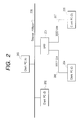
- Fig. 2 is a diagram showing the system structure of this embodiment.
- MFP analyzes an instruction from a client connected each network to set up each function by using printers, scanners and the like.
- reference numeral 201 represents MFP shown in Fig. 1.
- MFP 201 is connected to client PCs (information processing apparatus) 202, 203, 204, 205 via a network interface cable (10 BASE-T), an IEEE 1394 interface cable 206 and an IEEE 1284 interface cable 207.
- client PC runs on various types of software (control program) stored in a disk 6009 as a storage medium shown in Fig. 108 to be described later.
- the client PCs 202 and 203 connected to an Ethernet cable 208 designates an IP address and a port number to connect MFP 201 and outputs IP packet data.
- the client PC 204 connected to the IEEE 1394 interface 206 designates a node ID and a logical unit number (LUN) to connect MFP 201 and output SBP-2 packet data.
- the client PC 205 connected to the IEEE 1284 interface 207 designates a socket number node ID to connect MFP 201 and output IEEE 1284.4 packet data.
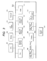
- Fig. 3 is a diagram showing the hardware structure of the controller 101 of this embodiment shown in Fig. 1.
- a CPU 301 is connected via a bus 313 to a memory (RAM) 302, a user interface (operation unit) 110 constituted of an LCD display 303 and a keyboard 304, a ROM 314 and a disk 315.
- Various programs for device management and data such as attribute tables stored in the disk (storage medium) 315 such as a hard disk and a floppy disk shown in Fig. 107 realize the above-described functions, and are sequentially written in the memory (RAM) 302 when necessary.
- the disk 315 may be a removable disk relative to MFP 201 or may be a disk built in MFP 201.
- Programs shown in Fig. 107 may be downloaded and stored in the disk 315 by the clients PCs 202, 203, 204 and 205 or another MFP via the network cable (10 BASE-T) 208, IEEE 1394 interface cable 206 and IEEE interface cable 207.
- the disks 315 and 6009 store not only those programs definitely illustrated in Figures but also all programs explained in this specification.
- the LCD display 303 and keyboard 304 constitute the user interface (operation unit) 110 shown in Fig. 1.
- CPU 301 operates to write data to the display 303 to display it, and to read data from the keyboard 304 to input a user instruction.
- the bus 313 is connected to a network interface connector 305, an IEEE 1394 interface connector 306 and an IEEE 1284 interface connector 307 which correspond to the network interface 107, IEEE 1394 interface 108 and IEEE 1284 interface 109 shown in Fig. 1, respectively and which are connected to the Ethernet (10 BASE-T) cable 208, IEEE 1394 cable 206 and IEEE 1284 cable 207 shown in Fig. 2.
- CPU 301 reads/writes data via these interfaces to communicate with devices via the interfaces.
- the bus 313 is also connected to a laser beam printer engine 308, a finisher 309, a scanner engine 310, a laser beam printer engine 311 and an ink jet printer engine 312 which correspond to the laser beam printer engine 103, finisher 106, scanner engine 102, laser beam printer engine 104 and ink jet printer engine 105.
- CPU 301 reads/writes data relative to these engines to control the operations of the printer engine, scanner engine and the like and acquire various states.
- the laser beam printer engine 308, finisher 309, scanner engine 310, laser beam printer engine 311 and ink jet printer engine 312 may not be provided in MFP 201 but may be discrete devices on the network which are controlled by the controller 101 of MFP 201. These engines have various sensors to check their engine states and the originals and recording sheets to be processed.
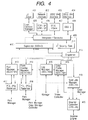
- Fig. 4 shows the structure of software (management/control programs) stored in the disk 315 of the controller 101.
- the software (control programs) is executed by CPU 301.
- solid lines indicate a flow of data and control, and broken lines indicate settings and acquisition of functions.
- Reference numeral 401 represents a user interface driver which controls the LCD display 303 and keyboard 304.
- Reference numeral 405 represents a user interface manager (control program) which analyzes an instruction input from the UI driver 401 by a user, generates a command packet shown in Fig. 46 and outputs it to an interpreter (control program) 409.
- the user interface manager 405 also analyzes a command packet input from the interpreter 409 and displays the results on the LCD display 303 via the UI driver (control program).
- Reference numeral 402 represents a network interface driver (control program) which controls the network interface controller 305 to perform a physical layer (physical packet) process for a network packet, i.e., extract a transport packet from a physical packet or generate a physical packet from a transport packet.
- Reference numeral 406 represents a TCP/IP - UDP/IP process module which processes a transport packet output from a network interface 402 to extract a command packet and output it to the interpreter 409. This module 406 also generates a transport packet from a command packet output from the interpreter 409 and outputs it to the network interface 402.
- Reference numeral 403 represents an IEEE 1284 driver (control program) which controls the IEEE 1284 interface 307.
- Reference numeral 407 represents an IEEE 1284.4 process module (control program). IEEE 1284.4 is the standards of a transport layer intended to be used mainly with an IEEE 1284 interface.
- the IEEE 1284.4 process module (control program) 407 processes a transport packet output from the IEEE 1284 driver 403 to extract a command packet and output it to the interpreter 409. This module 407 also generates a transport packet from a command packet output from the interpreter 409 and outputs it to the IEEE 1284 driver 403.
- Reference numeral 404 represents an IEEE 1394 driver (control program) which controls the IEEE 1394 interface 306.
- Reference numeral 408 represents a module (control program) which processes an SBP -2 (serial bus protocol which is a transport layer of IEEE 1394.
- the SBP-2 process module 408 processes a transport packet output from the IEEE 1394 driver 404 to extract a command packet and output it to the interpreter 409.
- This module 1394 also generates a transport packet from a command packet output from the interpreter 409 and output it to the IEEE 1394 driver 404.
- the packet interpreter 409 analyzes a command packet input from each of the transport process units 406, 407 and 408 and from the user interface manager 405 and generates a command.
- the packet interpreter 409 also generates a command packet upon request from other modules (control program).
- the interpreter 409 processes only the command packet input from an effective sub address, and cancels or discards the command packet input from other sub addresses.
- the supervisor 410 supervises the operation of the controller by storing in the disk 315 various data shown in Fig. 7 (attribute table), Fig. 9 (sub address - service ID corresponding table), Fig. 11 (service ID - task type corresponding table), Fig. 13 (user certification table), Fig. 14 (access control table), Fig. 16 (event set table), Fig. 17 (event format table), Fig. 114 (account ID table), and Fig. 115 (table of user ID changeable to account ID).
- the supervisor 410 refers to and change various data held by itself, each manager (font manger 413, form overlay manager 414, log manager 415, color profile manager 416, print managers 501 to 509, scan job manager 419, and copy job managers 601 to 608), and each controller (printer controllers 510 to 512 and scanner controller 420).
- Reference numeral 411 represents a security gate which limits a command input so that only a user having a user right is allowed to access MFP 201 in accordance with the user certification table (Fig. 13) and access control table (Fig. 14).
- Reference numeral 412 represents a dispatcher (control program) dispatched a command input from the interpreter 409 to each resource manager (font manger 413, form overlay manager 414, log manager 415, color profile manager 416) and each job manager (print managers 501 to 509, scan job manager 419, and copy job managers 601 to 608).
- the font manager 413 manages fonts and stores in the disk 315 the data such as shown in Fig. 26 (attribute table) and Fig. 28 (font table). Fonts (stored in the disk 315 or ROM 314) managed by the font manager 413 are passed to PDL rasterizers 417 and 418 and used for a print job process.
- the form overlay manager 414 manages form overlays.
- the form overlay manager 414 stores in the disk 315 the data shown in Fig. 29 (attribute table) and Fig. 31 (form table).
- Form overlays (stored in the disk 315 or ROM 314) managed by the form manager 414 are passed to the PDL rasterizers 417 and 418 and used for a print job process.
- the log manager 415 manages logs.
- the log manager 415 stores in the disk 315 the data shown in Fig. 32 (attribute table) and Fig. 34 (log table).
- a log is output from each manager and managed by the log manager.
- a log file is stored in RAM 302 or disk 315 and updated each time when necessary.
- the color profile manager 416 manages color profile data for the color matching by the color scanner and color printer.
- the color profile manager 416 stores in the disk 315 the data shown in Fig. 37 (attribute table) and Fig. 39 (color profile table).
- Color profiles managed by the color profile manager 416 are passed to each printer controller (control program) 510, 511, 512 and a scanner controller (control program) 420 and used for a print job process, a copy job process and a scan job process.
- the PDL (page descriptive language) rasterizer 417 processes document data written by PS (registered trademark) which is one kind of PDL, and outputs image data.
- the scan job manager 419 manages a scan job.
- the scan job manager 419 stores in the disk 315 the data shown in Fig.
- the scan job manager 419 instructs the scan controller 420 to executes scanning.
- Reference numeral 420 represents a scanner controller for controlling the scanner engine 310.
- the scanner controller 420 stores in the disk 315 the data shown in Fig. 44 (attribute table) representative of the function, state and performance of the scanner engine 310.
- Both the scan job manager 419 and scanner controller 420 have the data (Figs. 22 and 44) representative of the function and performance, and the data representative of the function is not necessarily required to be the same.
- the function can be limited by rewriting the data (Fig. 22) possessed by the scan job manager 419 via the supervisor 410.
- the font manager 413, form overlay manager 414, log manager 415, and color profile manager 416 are resource management programs.
- the scan job manager 419, print job managers 501 to 509 and copy job manager 601 to 608 are logical device (scanner, printer) control programs.
- a laser beam printer controller 510, the scanner controller 420 are physical device (printer, scanner) control programs.
- Fig. 5 shows the details of the software (control program) structure shown in Fig. 4.
- Each print manager receives a command from the dispatcher 412, as will be later described.
- the dispatcher 412 shown in Fig. 5 is the same as that shown in Fig. 4 and dispatches a command packet to the print job managers (control program) 501 to 509 which manages a print job.
- Each print job manager stores the data such as shown in Fig. 18 (attribute table) in the disk 315 to always monitor its own function and the like.
- Each print job manager is assigned for its print job a predetermined printer controller (LBP controller 510, LBP controller 511, ink jet controller 512, controller 51, or an arbitrary combination of controllers 10 to 512) and a printer engine connected to the controller.
- This assignment of the printer controller (control program) is written in the data of an attribute ID 2001 shown in Fig. 18.
- the print job manager 508 has a function of dynamically selecting a printer engine. This function is written in the data (attribute table) possessed by the print job manager 508.
- Each print manager stores in the disk 315 the data such as shown in Fig. 20 (job table) and Fig. 21 (job request table), which data indicates how the input print job is executed by which printer controller.
- the printer controllers 510 to 512 control the printer engines 308, 311 and 312.
- the printer controller 510 controls also the finisher 309.
- Each printer controller stores the data such as shown in Fig. 40 (attribute table) in the disk 315, the data indicating the function, state and performance of the corresponding printer engine.
- Each controller stores in the disk 315 the data such as shown in Fig. 42 (job queue table) indicating the state of an input job.
- the print job managers 501 to 509 and printer controller 510 to 512 each store in the disk 315 the data such as shown in Fig. 18 (attribute table) and Fig. 40 (attribute table), the data indicating the function and performance.
- the print job manager has the whole of performances and common performances possessed by the controllers used by the print job manager. However, a portion of these functions may be changed by changing the data (Fig. 18) possessed by the print job manager through the supervisor 410.
- the print job managers 503 and 509 use the same printer controller 512 and can provide the same function and performance, it can make the print job manager 503 to print out a color print and the print job manager 509 not to print out a color print, by a setting process for data possessed by the print manager, as will be later described.
- Fig. 6 is the details of the software (control program) structure shown in Figs. 4 and 5.
- a copy job manager to be described later also receives a command from the dispatcher 412.
- the dispatcher shown in Fig. 6 is the same as that shown in Fig. 4, and dispatches a command packet to copy job managers (control program) 601 to 608 which control a copy job.
- Each copy job manager stores the data such as shown in Fig. 24 (attribute table) in the disk 315.
- Each copy job manager is assigned for its copy job a predetermined printer controller and scanner controller and a printer engine and scanner engine connected thereto. This assignment of the printer controller and scanner controller is written in the data of an attribute ID 2001 shown in Fig. 28.
- the print job manager 608 has a function of dynamically selecting a printer engine. This function is written in the data (attribute ID 2002) possessed by the coy job manager 608.
- Each copy manager stores in the disk 315 the data such as shown in Fig. 20 (job table) and Fig. 21 (job request table), which data indicates how the input copy job is executed by which printer controller and scanner controller.
- the printer controllers 510 to 512 control the printer engines which are the same as those shown in Fig. 5.
- Fig.7 shows the data (attribute table) which the supervisor (control program) 410 stores in the disk 315 and manages.
- This table provides the function outline, connection information, security information, account information (current account data, account limit data) to be described later, respectively of MFP 201.
- Each row of the table corresponds to an information unit (record), and the data is constituted of a collection of a plurality of records.
- Each record is constituted of an attribute ID 701, a type ID 702, and an attribute value 703.
- the attribute ID 701 represents the information type such as shown in Fig. 8.
- the meaning of the corresponding value 703 is defined.
- the attribute ID 701 is used in common for all devices. Devices having the same attribute ID share the same type of information.
- the type ID 702 indicates what data type the value 703 has, and is used when the value 703 is interpreted.
- the type ID is determined solely by the attribute ID, and is defined uniquely in each device.
- the attribute table has both the attribute ID 701 and type ID 702
- a corresponding table between the attribute ID and type ID may be stored as the data separately from the attribute table and only the attribute ID and value may be stored in the attribute table.
- the value 703 indicates an attribute value corresponding to the attribute ID 701.
- Fig. 8 shows the details of the attribute ID 701 and type ID 702 of the attribute table shown in Fig. 7.
- An attribute ID 102 "supported security level list” is a list of settable security levels necessary for requesting an operation to the supervisor. The security levels are shown in an access control table shown in Fig. 14.
- An attribute ID 103 "current security level” indicates a security level currently set to the supervisor.
- An attribute ID 501 "supported event list” is a list of event IDs uniquely defined for each event type and capable of being notified to the supervisor. Setting an actual event transmission is performed by setting the connection type and destination of an event notice together with the event ID to an event set table shown in Fig. 16.
- the value "Table Data" of the attribute table shown in Fig. 7 indicates that the value is the data having the type format (52 to 104) of the type ID.
- Fig. 9 is a corresponding table between a sub address and a service ID.
- This table is stored in the disk 315 as the attribute value of the attribute ID 1001 (sub address - SID corresponding table) of the attribute table shown in Fig. 7.
- the sub address - SID corresponding table indicates which service (e.g., printing and download of font) can be received when a command packet is issued to which sub address.
- the interpreter 409 judges for each connection type whether a job service is provided or not.
- each row corresponds to an information unit (record), and the data is constituted of a collection of a plurality of records.
- connection type ID 801 is an identifier representative of the connection type.
- Fig. 10 is a diagram illustrating the meanings of each connection type ID, in which 0 indicates "Internal (user interface)", 1 indicates TCP/IP (network), 2 indicates IEEE 1284.4 (IEEE 1284), and 3 indicates SBP-2 (IEEE 1394).
- the sub address 802 indicates a sub address for each connection type. Although the user interface has no sub address, a sub address is assigned for the convenience sake. A command packet is sent from the user interface by using this sub address information.
- the service ID 803 is an identifier indicating the contents of service.
- the service ID 803 is assigned to each manager shown in Figs. 4 to 6 in one-to-on correspondence.
- the effective flag 804 indicates whether the sub address is valid or not. If this value is true (YES), the sub address is effective and the user can issue a command packet to the sub address. If this value is false (NO), the sub address is invalid, and even if a command packet is issued to the sub address, it is cancelled. In the example shown in Fig. 8, service of the service ID 8 (print job manager) using the connection type ID 2 (Ieee 1284) cannot be used.
- the effective user list 805 is a list of user IDs which can receive service if the sub address is effective.
- the invalid user list 806 is a list of user IDs which cannot receive service even if the sub address is effective. Only one of the effective user list 805 and invalid user list 806 is set with a value.
- Fig. 11 is a corresponding table between a service ID and a task type.
- the task type indicates which task (which printer manager or the like) processes a requested task (service).
- This table is stored in the disk 315 as the attribute value of the attribute ID 1002 (table of SID - task type) of the attribute table shown in Fig. 7.
- the service ID - task type table indicates which type of service the service ID is assigned.
- Each row of the table corresponds to an information unit (record), and the data is constituted of a collection of a plurality of records.
- Each record includes a service ID 901 and a task type 902.
- the task type 902 indicates the type of service.
- Fig. 12 shows the meanings of the values of the task type 902.
- the service ID is in one-to-one correspondence with a manager which provides service. Therefore, the service ID is also used for accessing a function table possessed by each manager.
- the function table is also possessed by each printer controller and each scanner controller. Therefore, a controller ID corresponding to the service ID is also assigned to the printer controller and scanner controller to access them. Therefore, the service ID - task type corresponding table also manages as to which type of the controller corresponds to the controller ID.
- the task type 201 indicates the printer controller
- the task type 202 indicates the scanner controller.
- the controller ID is in one-to-one correspondence with each controller shown in Figs. 4 and 5.
- Fig. 13 is a user certification table possessed by the supervisor.
- This table shows certification information of a user capable of using devices.
- This table is stored in the disk 315 as the attribute value of the attribute ID 1003 (user certification table) of the attribute table shown in Fig. 7.
- the user certification table contains a combination of an effective user ID and a password, together with information of whether the user has an administrator privilege.
- Each row of the table corresponds to an information unit (record), and the data is constituted of a collection of a plurality of records.
- Each record includes a user ID 1001, a password 1002, and an administrator privilege flag 1003.
- the administrator privilege flag 1003 indicates whether the user has an administrator privilege.
- Fig. 14 is an access control table possessed by the supervisor.
- the access control table shows a security level of each service. This table is stored in the disk 315 as the attribute value of the attribute ID 1004 (access control table) of the attribute table shown in Fig. 7.
- the access control table contains a security level for each service ID and a list of users permitted to receive service. Each row of the table corresponds to an information unit (record), and the data is constituted of a collection of a plurality of records. Each record includes a service ID 1101, a security level 1102, and a user ID list 1103.
- the security level 1102 indicates certification information necessary for receiving the service designated by the service ID 1101, i.e., for issuing a command packet to the manger designated by the service ID 1101.
- the security level 15 shows the meanings of security levels.
- the security level 0 indicates that user certification is not necessary, 1 indicates that only an administrator is discriminated, 2 indicates that only the certified user can receive service and that the user ID is used and the password is not used for the certification, and 3 indicates that only the certified user can receive service and that the user ID and password are used for the certification.
- the user ID list 1103 is a list of user (access) permitted user IDs if the security level 1102 is 2 or 3.
- Fig. 16 is an event set table possessed by the supervisor.
- the event set table is stored in the disk 315 as the attribute value of the attribute ID 502 (event set table) of the attribute table shown in Fig. 7.
- the event set table stores for each type of an event a transmission method and a destination of an event notice when a designated event occurs in a device.
- Each row of the table corresponds to an information unit (record), and the data is constituted of a collection of a plurality of records.
- Each record includes an event ID 1201, a connection type 1202, and a notice destination address 1203.
- the destination is constituted of a connection type and a notice destination address dependent upon the connection type.
- the event ID 1201 identifies the type of an event and is uniquely defined in each device.
- an event ID 200 indicates no paper sheet
- an event ID 399 indicates no toner
- an event ID 432 indicates no ink
- event ID 234 indicates a cover-open of MFP.
- the connection type ID 1201 identifies the connection type for transmitting an event notice.
- the value of this connection type ID the value same as that used by the sub address - service ID corresponding table shown in Fig. 9 is used.
- the notice destination address 1203 indicates a notice destination of the event proper for the connection type 1202.
- a notice may be sent to a client or each device when a job exceeding an account limit value is requested, when the account value becomes near the account limit value, or when the client whose access privilege is not permitted accesses.
- Fig. 17 is an event format table possessed by the supervisor.
- the event format table shows the contents of an event.
- the event format table is stored in the disk 315 as the attribute value of the attribute ID 503 (event format table) of the attribute table shown in Fig. 7.
- the event format table stores, for each event ID uniquely defined in each device, the format of additional data to be transmitted as the event notice.
- Each row of the table corresponds to an information unit (record), and the data is constituted of a collection of a plurality of records.
- Each record includes an event ID 1301 and an event format 1302.
- the event format 1302 shows a format of additional data to be transmitted as the event notice, and is given as the attribute ID list.
- the attribute ID is uniquely defined in each device, and its type is also determined solely by the attribute ID.
- the format of additional data can be identifier.
- the attribute ID 676 of the event format 1302 indicates a paper size
- the attribute ID 756 indicates the type of paper
- the attribute ID 666 indicates the type of toner
- the attribute ID 698 indicates the type of ink
- the attribute ID 600 indicates the position of a cover.
- the event transmission method and destination are set to the data (attribute table) possessed by each manager and controller so that an event occurred in each manager and controller can be notified.
- the format of additional data of such an event is stored in the event format table shown in Fig. 13. When a designated event occurs, the contents defined by the event format are notified together with data predetermined for each event ID.
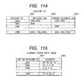
- a table shown in Fig. 114 shows information on each account ID possessed by the supervisor.
- This table is stored in the disk 315 as the attribute value of the attribute ID 1105 (account ID table) of the attribute table shown in Fig. 7.
- This table shows a relation between an effective account ID, its user ID, and chargeable user ID.
- Each row of the table corresponds to an information unit (record), and the data is constituted of a collection of a plurality of records.
- Each record includes an account ID 8301, its user ID list 8302, and a chargeable user ID list 8303.
- the value used as the user ID cannot be used as the value of the account ID.
- the account ID is in one-to-one correspondence with its user ID.
- the number of user IDs may be zero.
- the account ID and chargeable user ID are in one-to-multiple relation and the number of user IDs may be zero.
- Fig. 115 is a current count data table possessed by the supervisor.
- This table shows a list of count data to be counted in the supervisor.
- This table is stored in the disk 315 as the attribute value of the attribute ID 401 (current count data table) of the attribute table shown in Fig. 7.
- Each row of the table corresponds to an information unit (record), and the data is constituted of a collection of a plurality of records.
- Each record includes a user ID or account ID 8401, and an attribute ID 8402.
- the meaning of the counter is the same as those of an attribute ID 402 "count data format". For example, count data 45, 78, 34, 13 of an account ID 2003 shows the number of prints having a paper size indicated by a count data format.
- Fig. 116 is a count data format table possessed by the supervisor.
- This table shows a list of attribute IDs.
- This table is stored in the disk 315 as the attribute value of the attribute ID 402 (count data format table) of the attribute table shown in Fig. 7.
- Each row of the table corresponds to an information unit (record), and the data is constituted of a collection of a plurality of records.
- Each record includes a user ID or account ID 8501, and an attribute ID 8502. Since the attribute ID is defined uniquely in each device, the meaning of the count data can be designated by designating the attribute ID.
- the attribute value 565 of the attribute ID 402 indicates the number of prints of a paper size A2
- the attribute value 545 indicates the number of prints of a paper size A4
- the attribute value 523 indicates the number of prints of a paper size A5.
- Fig. 117 is a count limit data table possessed by the supervisor.
- This table shows a maximum value which the attribute ID 401 "current count data" can take.
- This table is stored in the disk 315 as the attribute value of the attribute ID 403 (count limit data table) of the attribute table shown in Fig. 7.
- Each row of the table corresponds to an information unit (record), and the data is constituted of a collection of a plurality of records.
- Each record includes a user ID or account ID 8601, and a maximum value 8602. If any one of the value of the attribute ID 401 "current count data" exceeds the count limit data, CPU 301 invalidates the effective flag in the sub address - service ID corresponding table shown in Fig. 9 to thus invalidate all services by the manager.
- Fig. 118 is a count unit price data table possessed by the supervisor.
- This table shows a unit price of a money denomination unit per one count by the attribute ID held in the attribute ID 402 "count data format".
- This table is stored in the disk 315 as the attribute value of the attribute ID 404 (count unit price data table) of the attribute table shown in Fig. 7.
- Each row of the table corresponds to an information unit (record), and the data is constituted of a collection of a plurality of records.
- Each record includes a user ID or account ID 8701, and a unit price 8702.
- Fig. 119 is a current account data table possessed by the supervisor.
- This table shows a total sum of the value of the attribute ID 401 "current count data” multiplied by the value of the value of the attribute ID 404 "count unit price data".
- This table is stored in the disk 315 as the attribute value of the attribute ID 405 (current account data table) of the attribute table shown in Fig. 7.
- Each row of the table corresponds to an information unit (record), and the data is constituted of a collection of a plurality of records.
- Each record includes a user ID or account ID 8801, and a current account 8802.
- Fig. 120 is an account limit data table possessed by the supervisor. This table shows a maximum value the attribute ID 405 "current account data” can take. This table is stored in the disk 315 as the attribute value of the attribute ID 406 (account limit data table) of the attribute table shown in Fig. 7. Each row of the table corresponds to an information unit (record), and the data is constituted of a collection of a plurality of records. Each record includes a user ID or account ID 8901, and an account limit 8902. If the attribute ID 405 "current account data" exceeds the attribute ID 406 "account limit data", CPU 301 invalidates the effective flag in the sub address - service ID corresponding table shown in Fig. 9 to thus invalidate all services by the manager.
- Fig. 18 shows the data (attribute table) which each print job manager (control program) 501 - 509 stores in the disk 315.
- This table shows the performance and function of a print job which the print manager can process.
- Each row of the table corresponds to an information unit (record), and the data is constituted of a collection of a plurality of records.
- the contents of each record are the same as those of the supervisor shown in Fig. 7, and are constituted of an attribute ID 1401, a type ID 1402, and a value 1403.
- Fig. 19 is a diagram showing the attribute ID 1401 and type ID 1402 of the attribute table shown in Fig. 18.
- type ID 203 job table type
- type ID 204 job request table type
- type ID 81 prohibited attribute combination list type 1
- type ID 82 prohibited attribute combination list type 2
- type ID 83 prohibited attribute combination list type 3
- type ID 84 prohibited attribute combination list type 4
- type ID 85 prohibited attribute combination list type 5
- An attribute ID 601 "supported data download process” indicates a process of transmitting print document data to each device.
- the supported process includes a process wherein document data is contained in a job and a process wherein a reference pointer (unified resource locator (URL)) of document data is contained in a job and the document data designated by the reference pointer is read by each device when necessary.
- a reference pointer unified resource locator (URL)
- Attribute IDs 801 to 805 indicate prohibition setting attributes for limiting the attribute to be set to the print job which is given to the print manager. For example, these attribute IDs are used to indicate a limit item such as that the finisher setting becomes impossible when the number of copies exceeds 100.
- the prohibition setting attributes include five types of limiting the attribute.
- An attribute ID 801 holds a list of a plurality of pairs of (one attribute ID 1) and (another attribute ID 2), as represented by ⁇ attribute ID1 : ⁇ attribute ID 2 ⁇ . This means that if the attribute ID 1 is set, the other attribute ID 2 cannot be set in a print job script.
- An attribute ID 802 holds a list of a plurality of pairs of (an attribute ID 1, an operator identifier, and its value) and (another attribute ID 2), as represented by ⁇ attribute ID1 : operator identifier: value : ⁇ attribute ID 2 ⁇ . This means that if the result that for the attribute ID 1 an operator designated by the operator identifier is applied to the value, is true, then each attribute ID 2 cannot be set in a print job script.
- An attribute ID 803 holds a list of a plurality of pairs of (an attribute ID 1, an operator identifier 1, and its value 1) and (another attribute ID 2, anther operator identifier 2, and its value 2), as represented by ⁇ attribute ID1: operator identifier 1: value 1: ⁇ attribute ID 2; operator identifier 2; value 2 ⁇ . This means that if the result that for the attribute ID an operator designated by the operator identifier 1 is applied to the value 1, is true, then a print job script cannot be set in such a manner that for each attribute ID 2 the result of applying an operator identified by the operator identifier 2 to the value 2, becomes true.
- An attribute ID 804 holds a list of a plurality of pairs of [(an attribute ID 1, an operator identifier 1, and its value 1), (another operator identifier 3) and (another attribute ID 2, anther operator identifier 2, and its value 2)] and [another attribute ID3], as represented by ⁇ (attribute ID1: operator identifier 1: value 1) : operator identifier 3 : (attribute ID 2; operator identifier 2; value 2 ⁇ : ⁇ attribute ID 3 ⁇ .
- An attribute ID 805 holds a list of a plurality of pairs of [(an attribute ID 1, an operator identifier 1, and its value 1), (another operator identifier 3) and (another attribute ID 2, another operator identifier 2, and its value 2)] and [another attribute ID3, another operator identifier 4 and its value 4], as represented by ⁇ (attribute ID1: operator identifier 1: value 1) : operator identifier 3 : (attribute ID 2; operator identifier 2; value 2 ⁇ : ⁇ attribute ID 4; operator identifier 4; value 4 ⁇ .
- An attribute ID 2001 “list of IDs of controllers for executing a job (having a possibility of execution)" is a list of IDs of controllers for executing a print job, and the print job managers other than the print job manager 508 essentially correspond to the controllers for executing a job. Since the print job manager 508 dynamically select the controller in accordance with the function requested by a job, this attribute indicates a range of controller selection.
- An attribute ID 2002 “controller automatically selectable or not” indicates whether the print job manager automatically selects the controller. In this embodiment, only the print job manager 508 has this attribute as true.
- the other attributes ID are the same as those shown in the attribute table of the supervisor shown in Fig. 7.
- an attribute ID 101 "supported operation” is a list of operations capable of being issued to the corresponding print job manager.
- An attribute ID 406 "account limit data" limits an account for the print job executed by the corresponding print job manager. If the account limit is exceeded, only the service of this print job manager is invalidated and services of the other managers are not influenced.
- the attribute table of the print job manager shown in Fig. 18 is the attribute table (print job manager 504) for the service ID 4. Different attribute tables of the other attribute job managers 501, 502, 503, 505, 506, 507, 508 and 509 corresponding to the service IDs 1, 2, 3, 5, 6, 7, 8 and 9 are stored in the disk 315.
- An attribute ID 10001 "maximum printable number of copies” indicates the maximum printable number of copies which the print job can obtain.
- An attribute ID 106 "current status" shows the current status of the print job manager. The attribute value 0 indicates a normal state, the attribute value 1 indicates a normal state with restriction, and the attribute value 2 indicates an abnormal state that service is not available.
- An attribute ID 107 "list of attributes to be referred when job can be executed with restriction” shows those attributes when the attribute value of the attribute ID 106 is 1 indicating the normal state with restriction.
- An attribute ID 108 "list of trouble reasons” shows those attributes indicating "reason for trouble” when the attribute value of the attribute ID 106 is 2 indicating an abnormal state and unavailable service.
- the scan job manager always changes dynamically the value of each of the attributes IDs 106, 107 and 108 and the value of each attribute indicated by the value of the attribute ID 107.
- Fig. 20 shows data (job table) possessed by a print job manager.
- This table shows a correspondence between the name of a file storing the entity of a job managed by the print manager and a job ID.
- This table is stored in RAM 302 as the attribute value of the attribute ID (job table) of the attribute table shown in Fig. 18.
- the print job manager dynamically changes the job table in RAM 302 and stores it in the disk 315 when necessary.
- Each row of the table corresponds to an information unit (record), and the data is constituted of a collection of a plurality of records.
- Each record includes a job ID 1501 and the name 1502 of a file storing the entity of the job.
- the job ID 1501 is an identifier of a job assigned by the print job manager which received the job.
- the job file name 1502 indicates the name of a file storing the entity of the job.
- the entity of a job is constituted of a plurality of pairs of an attribute ID, an attribute value size and an
- Fig. 21 is a job request table possessed by the print manager and indicating a relation between a job to be managed by the print manager and a job to be executed by the controller.
- This table is stored in the disk 315 as the attribute value of the attribute ID 2004 (job request table) of the attribute table shown in Fig. 18.
- the job request table indicates which controller is executing the job managed by the print job manager as which job.
- Each row of the table corresponds to an information unit (record), and the data is constituted of a collection of a plurality of records.
- Each record includes a controller ID 1504 and a job ID 1505 assigned to the controller.
- the job ID 1503 is an identifier of a job assigned by the print job manager which received the job, and corresponds to the Job ID 1501 of the job table (Fig. 20).
- the controller ID 1504 is an identifier of the controller which is executing the job.
- the job ID 1505 is an identifier of the job assigned by the controller which executes the job.
- Fig. 22 shows the data (attribute table) possessed by the scan job manager 419.
- This table shows the performance and function of a scan job which the scan job manager can process.
- Each row of the table corresponds to an information unit (record), and the data is constituted of a collection of a plurality of records. The contents of each record are the same as those of the supervisor shown in Fig. 7, and are constituted of an attribute ID 1601, a type ID 1602, and a value 1603.
- Fig. 23 is a diagram showing the attribute ID and type ID of the attribute table shown in Fig. 22.
- An attribute ID 602 "supported data upload process" indicates a process of transmitting scan document data to each device.
- the supported process includes a process wherein document data is contained in a transmitted job and a process wherein a reference pointer (unified resource locator (URL)) of document data held in a device is contained in a transmitted job and the document data designated by the reference pointer is read by a host (client) when necessary.
- An attribute ID 1201 "list of supported image formats” indicates a supported image data format
- an attribute ID 1203 "settable resolution list” indicates a settable resolution. When a scan job is issued, the data format and resolution in these tables can be designated.
- An attribute ID 1204 "distinguishable original type” indicates a type (monochrome or color, text or image and the like) of an original distinguishable with a sensor function of the scanner engine 102.
- a combination of types can be selected and the data format and resolution for each such a combination can be designated.
- One of the types shows a specific value representative of "prescan”. This type is used for selecting the data format and resolution when a prescan is set.
- the job table for the attribute ID 108 is the same as that shown in Fig. 20 and possessed by the print manager.
- the other attribute IDs are the same as those used in the attribute table of the supervisor shown in Fig. 7. However, the setting and influence range is limited only to those under the management of the scan job managers belonging to the attribute table.
- the type IDs other than the type ID 203 (job table type) in the attribute table shown in Fig. 23 are the same as those used in the attribute table of the supervisor shown in Fig. 7.
- An attribute ID 106 "current status" shows the current status of the scan job manager.
- the attribute value 0 indicates a normal state
- the attribute value 1 indicates a normal state with restriction
- the attribute value 2 indicates an abnormal state that service is not available.
- An attribute ID 107 "list of attributes to be referred when job can be executed with restriction” shows those attributes when the attribute value of the attribute ID 106 is 1 indicating the normal state with restriction.
- An attribute ID 108 "list of trouble reasons” shows those attributes indicating "reason for trouble” when the attribute value of the attribute ID 106 is 2 indicating an abnormal state and unavailable service.
- the scan job manager always changes dynamically the value of each of the attributes IDs 106, 107 and 108 and the value of each attribute indicated by the value of the attribute ID 107.
- Fig. 24 shows the data (attribute table) possessed by each of the copy job managers 601 to 608. This table shows the performance and function of a copy job which the copy job manager can process.
- Each row of the table corresponds to an information unit (record), and the data is constituted of a collection of a plurality of records. The contents of each record are the same as those of the supervisor shown in Fig. 7, and are constituted of an attribute ID 1701, a type ID 1702, and a value 1703.
- Fig. 25 is a diagram showing the attribute ID 1701 and type ID 1702 of the attribute table shown in Fig. 24.
- An attribute ID 1302 "color print available or not”, an attribute ID 1303 "supported finishing type”, an attribute ID 1304 “maximum settable resolution”, an attribute ID 1305 “minimum settable resolution”, an attribute ID 2001 "list of controller IDs having a possibility of executing a job”, an attribute ID 200 "controller automatically settable or not”, and an attribute ID 2003 "job table” are the same as those described with respect to the print job manager and scan job manager.
- the attribute IDs and type IDs other than the attribute ID 1302 "color print available or not", attribute ID 1303 "supported finishing type”, attribute ID 1304 “maximum settable resolution”, attribute ID 1305 “minimum settable resolution”, attribute ID 2001 "list of controller IDs having a possibility of executing a job”, attribute ID 200 "controller automatically settable or not”, attribute ID 2003 "job table” and a type ID 203 (job table type) are the same as those used by the attribute table of the supervisor shown in Fig. 7.
- the attribute table of the copy job manager shown in Fig. 24 corresponds to the attribute table (copy job manager 608) having the service ID 18, and different attribute table corresponding to the copy job managers 601, 602, 603, 604, 605, 606 and 607 are stored in the disk 315.
- An attribute ID 10001 "maximum printable number of copies” shows the maximum number of copies printable by a copy job.
- An attribute ID 106 "current status” shows the current status of the copy job manager. The attribute value 0 indicates a normal state, the attribute value 1 indicates a normal state with restriction, and the attribute value 2 indicates an abnormal state and unavailable service.
- An attribute ID 107 "list of attributes to be referred when job can be executed with restriction” shows those attributes when the attribute ID 106 has the attribute value 1 indicating the normal state with restriction.
- An attribute ID 108 "list of troubles” shows those attributes of "reason of trouble” when the attribute value of the attribute ID 106 is 2 indicating the abnormal state and unavailable service.
- the copy job manager always changes dynamically the value of each of the attributes IDs 106, 107 and 108 and the value of each attribute indicated by the value of the attribute ID 107.
- Fig. 26 shows the data (attribute table) possessed by the font manager 413.
- This table shows the type of fonts usable by the font manager and the list of fonts under management by the font manager.
- Each row of the table corresponds to an information unit (record), and the data is constituted of a collection of a plurality of records. The contents of each record are the same as those of the supervisor shown in Fig. 7, and are constituted of an attribute ID 1801, a type ID 1802, and a value 1803.
- Fig. 27 is a diagram showing the attribute ID 1801 and type ID 1802 of the attribute table shown in Fig. 26.
- the attribute IDs and type IDs other than an attribute ID 601 "supported data download process”, an attribute ID 602 "supported data upload process”, an attribute ID 1501 "list of supported font types”, an attribute ID 1502 "maximum number of current fonts”, an attribute ID 1504 "list of stored fonts", and a type ID 150 "font table” are the same as those of the attribute table of the supervisor shown in Fig. 7. However, the setting and influence range is limited only to those under the management of the font manager belonging to the attribute table.
- the attribute ID 601 "supported data download process” and attribute ID 602 "supported data upload process” are the same as those described with the print job manager and scan job manager, and indicate the download and upload processes for supported font data.
- An attribute ID 106 "current status" shows the current status of the font manager.
- the attribute value 0 indicates a normal state
- the attribute value 1 indicates a normal state with restriction
- the attribute value 2 indicates an abnormal state and unavailable service.
- An attribute ID 107 "list of attributes to be referred when job can be executed with restriction” shows those attributes when the attribute ID 106 has the attribute value 1 indicating the normal state with restriction.
- An attribute ID 108 "list of troubles” shows those attributes of "reason of trouble” when the attribute value of the attribute ID 106 is 2 indicating the abnormal state and unavailable service.
- the font manager always changes dynamically the value of each of the attributes IDs 106, 107 and 108 and the value of each attribute indicated by the value of the attribute ID 107.
- Fig. 28 is a font table possessed by the font manager. This table is stored in the disk 315 as the attribute value of the type ID 1504 (font table) of the attribute table shown in Fig. 26.
- the font table shows which fonts the font manager currently manages. Each row of the table corresponds to an information unit (record), and the data is constituted of a collection of a plurality of records. The contents of each record are a font ID 1901, a font type 1902, a font name 1903 and a font data file name 1904.
- the font data is stored in the disk 315, and the font ID 1901 is an identifier of a font assigned by the font manager when font data is downloaded in RAM 302.
- Fig. 29 shows the data (attribute table) stored in the disk 315 and possessed by the form overlay manager 414.
- This table shows the format of a form overlay the form overlay manager can process and a list of current form overlays the form overlay manager manages.
- Each row of the table corresponds to an information unit (record), and the data is constituted of a collection of a plurality of records. The contents of each record are the same as those of the supervisor shown in Fig. 7, and are constituted of an attribute ID 2001, a type ID 2002, and a value 2003.
- Fig. 30 is a diagram showing the attribute ID and type ID of the attribute table shown in Fig. 29.
- the attribute IDs and type IDs other than an attribute ID 601 "supported data download process", an attribute ID 602 "supported data upload process”, an attribute ID 1601 “list of formats of supported font overlays", an attribute ID 1602 “maximum number of storable form overlays”, an attribute ID 1603 "number of form current form overlays”, an attribute ID 1604 "list of stored form overlays", and a type ID 160 "form table” are the same as those of the attribute table of the supervisor shown in Fig. 7. However, the setting and influence range is limited only to those under the management of the form overlay manager belonging to the attribute table.
- the attribute ID 601 "supported data download process” and attribute ID 602 "supported data upload process” are the same as those described with the print job manager and scan job manager, and indicate the download and upload processes for supported form overlays.
- An attribute ID 106 "current status" shows the current status of the font overlay manager.
- the attribute value 0 indicates a normal state
- the attribute value 1 indicates a normal state with restriction
- the attribute value 2 indicates an abnormal state and unavailable service.
- An attribute ID 1067 “list of attributes to be referred when job can be executed with restriction” shows those attributes when the attribute ID 106 has the attribute value 1 indicating the normal state with restriction.
- An attribute ID 108 "list of troubles” shows those attributes of "reason of trouble” when the attribute value of the attribute ID 106 is 2 indicating the abnormal state and unavailable service.
- the form overlay manager always changes dynamically the value of each of the attributes IDs 106, 107 and 108 and the value of each attribute indicated by the value of the attribute ID 107.
- Fig. 31 is a form overlay table possessed by the form overlay manager 414. This table is stored in the disk 315 as the attribute value of the attribute ID 1604 (form overlay table) of the attribute table shown in Fig. 29.
- the form overlay table shows which form overlays the form overlay manager currently manages. Each row of the table corresponds to an information unit (record), and the data is constituted of a collection of a plurality of records. The contents of each record are a font overlay ID 2101, a form overlay data format 2102, a form overlay name 2103 and a form overlay data file name 2104.
- the form overlay data is stored in the disk 315, and the form overlay ID 2101 is an identifier of a form overlay assigned by the form overlay manager when form overlay data is downloaded in RAM 302.
- Fig. 32 shows the data (attribute table) stored in the disk 315 and possessed by the log manager 415.
- This table shows the list of logs the log manager currently manages.
- Each row of the table corresponds to an information unit (record), and the data is constituted of a collection of a plurality of records.
- the contents of each record are the same as those of the supervisor shown in Fig. 7, and are constituted of an attribute ID 2201, a type ID 2202, and a value 2203.
- Fig. 33 is a diagram showing the attribute ID and type ID of the attribute table shown in Fig. 32.
- the attribute IDs and type IDs other than an attribute ID 602 "supported data download process", an attribute ID 703 "number of stored logs", an attribute ID 1704 "log table”, an attribute ID 1705 “log format table”, a type ID 170 “log table”, and a type ID 171 "log format table type” are the same as those of the attribute table of the supervisor shown in Fig. 7.
- the setting and influence range is limited only to those under the management of the log manager belonging to the attribute table.
- the attribute ID 601 "supported data download process” and attribute ID 602 "supported data upload process” are the same as those described with the print job manager and scan job manager, and indicate the download and upload processes for supported form overlays.
- An attribute ID 106 "current status" shows the current status of the font overlay manager.
- the attribute value 0 indicates a normal state
- the attribute value 1 indicates a normal state with restriction
- the attribute value 2 indicates an abnormal state and unavailable service.
- An attribute ID 1067 “list of attributes to be referred when job can be executed with restriction” shows those attributes when the attribute ID 106 has the attribute value 1 indicating the normal state with restriction.
- An attribute ID 108 "list of troubles” shows those attributes of "reason of trouble” when the attribute value of the attribute ID 106 is 2 indicating the abnormal state and unavailable service.
- the form overlay manager always changes dynamically the value of each of the attributes IDs 106, 107 and 108 and the value of each attribute indicated by the value of the attribute ID 107.
- Fig. 34 is a log table possessed by the log manager 415. This table is stored in the disk 315 as the attribute value of the attribute ID 1704 (log table) of the attribute table shown in Fig. 32.
- the log table shows which logs the form overlay manager currently manages.
- Each row of the table corresponds to an information unit (record), and the data is constituted of a collection of a plurality of records.
- the contents of each record are a log ID 2301 and a log data file name 2302.
- the log ID 2301 is an identifier of a log predetermined for each type.
- Fig. 35 shows the contents of log data stored in the disk 315 and managed by the log manager.
- the log data is constituted of a collection of log records.
- Each log record is constituted of a log format ID 2401, a record date/time 2402, and log data 2403.
- the log format ID 2401 make reference to log format information recorded in a log format table shown in Fig. 36, and indicates the format of the log data 2403.
- log data "12345,4,1. 23, "OK"" of a log format ID 1 means that the user ID which issues a job to the print job manager having the service ID 1 is "12345", the number of output paper sheets is "4", the quantity of toner is "1.23", and the job completion state is "OK".
- Fig. 36 is a log format table possessed by the log manager 415. This table is stored in the disk 315 as the attribute value of the attribute ID (log format table) of the attribute table shown in Fig. 32.
- the log format table shows the formats of logs in log data managed by the log manager 415. Each row of the table corresponds to an information unit (record), and the data is constituted of a collection of a plurality of records. The contents of each record are a log format ID 2501 and a log format 2502.
- the log format is described as a list of pairs of a service ID and an attribute ID.
- the attribute ID is defined uniquely for each device, and its type is also uniquely determined in accordance with the attribute ID. Therefore, by designating the attribute ID, the format of log data can be identified.
- the list of pairs of the service ID and attribute ID in the log format 2502 and the list of the value in the log data 2403 are in sequential correspondence with each other.
- the third pair of the service ID and attribute ID in the list of the log format 2502 corresponds to the format represented by the third value in the log data.
- the format "1 : 701, : 565,1 : 765,1 : 777" corresponds respectively to the user ID 1 of the user issued a job to the print job manager, the number of output paper sheets, the quantity of used toner, and the job termination state.
- the format "11 : 701,11 : 565,11 : 765,11 : 777" corresponds respectively to the user ID 11 of the user issued a job to the print job manager, the number of output paper sheets, the quantity of used toner, and the job termination state.
- Fig. 37 shows the data (attribute table) stored in the disk 315 and possessed by the color profile manager 416.
- This table shows the format of a color profile the color profile manager can process and the list of color profiles the color profile manager currently manages.
- Each row of the table corresponds to an information unit (record), and the data is constituted of a collection of a plurality of records. The contents of each record are the same as those of the supervisor shown in Fig. 7, and are constituted of an attribute ID 2601, a type ID 2602, and a value 2603.
- Fig. 38 is a diagram showing the attribute ID and type ID of the attribute table shown in Fig. 37.
- the attribute IDs other than an attribute ID 601 "supported data download process", an attribute ID 602 "supported data upload process”, an attribute ID 1801 “list of supported formats of color profile data”, an attribute ID 1802 “maximum number of storable color profiles”, an attribute ID 1804 "number of current color profiles”, an attribute ID 1804 "number of color profiles", and a type ID 180 "color profile table type) are the same as those of the attribute table of the supervisor shown in Fig. 7. However, the setting and influence range is limited only to those under the management of the color profile manager belonging to the attribute table.
- the attribute ID 601 "supported data download process” and attribute ID 602 "supported data upload process” are the same as those described with the print job manager and scan job manager, and indicate the download and upload processes for supported font data.
- An attribute ID 106 "current status" shows the current status of the color profile manager.
- the attribute value 0 indicates a normal state
- the attribute value 1 indicates a normal state with restriction
- the attribute value 2 indicates an abnormal state and unavailable service.
- An attribute ID 107 "list of attributes to be referred when job can be executed with restriction” shows those attributes when the attribute ID 106 has the attribute value 2 indicating the abnormal state and unavailable service.
- the color profile manager always changes dynamically the value of each of the attributes IDs 106, 107 and 108 and the value of each attribute indicated by the value of the attribute ID 107.
- Fig. 39 is a color profile table possessed by the color profile manager. This table is stored in the disk 315 as the attribute value of the attribute ID 1804 (color profile table) of the attribute table shown in Fig. 37.
- the color profile table shows which color profiles the color profile manager manages currently. Each row of the table corresponds to an information unit (record), and the data is constituted of a collection of a plurality of records. The contents of each record are a color profile ID 2701, a color profile format 2702 and a color profile data file name 2703.
- the color profile ID 2701 is an identifier of a color profile assigned by the color profile manager when the color profile data is downloaded.
- the color profile data is correction data to be used for color matching of the data sent from the scanner engine 102 or to the ink jet printer engine 105.
- Fig. 40 shows the data (attribute table) stored in the disk 315 and possessed by each of the printer controllers 510, 511 and 512.
- This table shows the function and performance of the print engine and finisher controlled by the print controller. The values regarding the function and performance cannot be rewritten.
- Each row of the table corresponds to an information unit (record), and the data is constituted of a collection of a plurality of records. The contents of each record are the same as those of the supervisor shown in Fig. 7, and are constituted of an attribute ID 2801, a type ID 2802, and a value 2803.
- Fig. 41 is a diagram showing the attribute ID and type ID of the attribute table shown in Fig. 40.
- the attribute IDs and type IDs other than an attribute ID 12 "controller type”, an attribute ID 12 "controller ID”, an attribute ID 5001 "color print available or not", an attribute ID 5002 "type of supported finishing), an attribute ID 5003 "maximum settable resolution”, an attribute ID 5004 "minimum settable resolution”, an attribute ID 5005 "job queue table”, and a type ID 500 "job queue table type” are the same as those of the attribute table of the supervisor shown in Fig. 7. However, the setting and influence range is limited only to those under the management of the printer controller belonging to the attribute table. Different attribute tables of the other printer controllers 511 and 512 corresponding to the service IDs 22 and 23 are stored in the disk 315.
- Fig. 42 is a job queue table possessed by the printer controller. This table is stored in the disk 315 as the attribute value of the attribute ID 5005 (job queue table) of the attribute table shown in Fig. 40.
- the job queue table shows the state of jobs to be managed and executed by the printer controller. Each row of the table corresponds to an information unit (record), and the data is constituted of a collection of a plurality of records.
- the contents of each record are a job ID 2901, a job status 2902 and a job data file name 2903.
- the job ID 2901 is an identifier of a job assigned by the printer controller when the job is issued to the printer controller.
- Fig. 43 is a diagram explaining the contents of the job status 2902 shown in Fig. 42.
- the job file name 2903 indicates the name of a file which stores the entity of the job.
- the job entity is constituted of a plurality sets of an attribute ID, an attribute size and an attribute value.
- Fig. 44 shows the data (attribute table) stored in the disk 315 and possessed by the scanner controller 420.
- This table shows the performance and function of the scanner engine to be controlled by the scanner controller. The value of the performance and function cannot be rewritten.
- Each row of the table corresponds to an information unit (record), and the data is constituted of a collection of a plurality of records. The contents of each record are the same as those of the supervisor shown in Fig. 7, and are constituted of an attribute ID 3001, a type ID 3002, and a value 3003.
- Fig. 45 is a diagram showing the attribute ID and type ID of the attribute table shown in Fig. 44.
- attribute IDs other than an attribute ID 12 "controller type”, an attribute ID 13 “controller ID”, an attribute ID 6001 "color scanning available or not”, an attribute ID 6002 "maximum original size”, an attribute ID 6003 "maximum settable resolution” and an attribute ID 6004 "minimum settable resolution” are the same as those of the attribute table of the supervisor shown in Fig. 7.
- the setting and influence range is limited only to those under the management of the printer controller belonging to the attribute table.
- Fig. 46 shows the structure of a command packet to be output to the interpreter 409 from the user interface manager 405, TCP/IP - UDP/IP process module 406, IEEE 1284.4 process module 407 and SBP-2 process module 408.
- This structure of the command packet shows also the structure of an answer packet and an event packet which are transferred from the interpreter 409 to the user interface manager 405, TCP/IP - UDP/IP process module 406, IEEE 1284.4 process module 407 and SBP-2 process module 408.
- the packet contains: a packet header 3101 at the head of the packet; a packet version 3102 indicating a packet structure version; a flag 3103 indicating a packet character; an operation code indicating an operation type; a block number 3105 used by the client to recognize an answer packet; a parameter length 3106 indication the length of a parameter 3110; a user ID 3107 and a password 3108 used for user certification; a status code 3109 which is used only with an answer packet and indicates the general state of an answer; and the parameter 3110 having a format determined for each operation code 3105.
- the parameter 3110 includes an access object service ID, an access object attribute ID and the like.
- the flag 3104 includes a flag 3111 indicating whether the packet is a command packet/event packet or an answer packet and a flag 3112 indicating that data to be entered in the parameter cannot be entered in the parameter and some data is also entered in the next packet.
- the length of the parameter 3110 is limited to the value (64 K bytes) indicated by the parameter length 3106.
- the client PCs 202 and 203 connected to the Ethernet interface 208 designate the IP address and port number to connect MFP 201 and output IP packet data to the network interface 305 (107).
- the client PC 204 connected to the IEEE 1394 interface 206 designates the node ID and LUN (logical unit number) to connect MFP 201 and output SBP-2 packet data to the IEEE 1394 interface 306 (108).
- the client PC 205 connected to the IEEE 1284 interface 207 designates the socket number to connect MFP 201 and output IEEE 1284.4 packet data to the IEEE 1284 interface 307 (1098).
- the network interface driver 402, IEEE 1284 interface driver 403 and IEEE 1394 interface driver 404 add the IP header, 1284 header and 1394 header to the top of each command packet shown in Fig. 46 and output the generated transport packet to the TCP/IP - UDP/IP process module 406, IEEE 1284.4 process module 407 and SBP-2 process module 408.
- the TCP/IP - UDP/IP process module 406, IEEE 1284.4 process module 407 and SBP-2 process module 408 process each input transport packet to extract the command packet and output it to the interpreter/generator 409.
- Fig. 47 is a flow chart illustrating a command packet process to be executed by MFP 201.
- each of the transport process modules 405, 406, 407 and 408 processes corresponding data input from each of the interfaces 401, 402, 403 and 404 to extract the command packet shown in Fig. 46.
- the extracted command packet together with the data input connection type information (connection type ID) and sub address are supplied to the interpreter 409 from the TCP/IP - UDP/IP process module 406, IEEE 1284.4 process module 407 and SBP-2 process module 408.
- the interpreter 409 refers to the sub address - service ID corresponding table (Fig.
- Step 3204 the command packet is cancelled to terminate the process. If the input data is valid, then at Step 3203 the command packet is analyzed in accordance with the packet structure shown in Fig. 46. After the packet analysis, each item shown in Fig. 46 is output as independent information.
- the access control table (Fig. 14) is referred to in accordance with the service ID to acquire the security level corresponding to the service ID and also acquire account data.
- Step 3206 it is checked whether the security level acquired at Step 3205 is 0 or 1. If the security level is 0 or 1, the security level is not checked (security gate 411), it is supplied to the despatcher 412. If it is judged at Step 3206 that the security level is neither 0 nor 1, it is checked at Step 3207 whether the security level is 2. If the security level is 2, it is checked at Step 3209 whether the user ID (UID) contained in the command packet exists in the user certification table (Fig. 13). If the user ID does not exists, it is judged that there is no privilege and at Step 3210 error answer information is generated and the interpreter 409 generates a packet (embeds the error information in the status code 3109) to transmit it to the command packet transmission side.
- UID user ID
- the user ID exists, it is passed to the dispatcher 412.
- the transmission side address is extracted from the transport packet (header). If it is judged at Step 3207 that the security level is not 2, it is checked whether the pair of the user ID and password contained in the command packet exists in the user certification table (Fig. 13). If the pair of the user ID and password does not exist, it is judged that there is no privilege, and at Step 3211 error answer information is generated and the interpreter 409 generates a packet and transmit is to the command packet transmission side. If the user ID exists, it is supplied to the dispatcher 412. At Step 3212 it is checked from the account data acquired at Step 3205 whether the charge object matches the user ID.
- Step 3213 it is checked whether there is a designated account ID. If there is a designated account ID, it is checked at Step 3214 from the account ID table (Fig. 114) whether the user ID belongs to the designated account ID or a charge is permitted. If neither of them are satisfied, it is judged that there is no privilege, and at Step 3215 error answer information is generated and the interpreter 409 generates a packet which is transmitted to the command packet transmission side. If the user ID belongs to the account ID or the charge is permitted, the account ID is supplied to the dispatcher 412. If it is judged at Step 3213 that there is no designated account ID, then at Step 3216 the account ID belonging to the user ID is searched from the account ID table (Fig.
- Step 3217 If the account ID cannot be found, it is judged that there is no privilege, and at Step 3217 error answer information is generated and the interpreter 409 generates a packet and transmits it to the command packet transmission side. If the account ID belonging to the user ID is found, the account ID is supplied to the dispatcher 412. At Step 3218 the dispatcher 412 determines the dispatch destination manager in accordance with the service ID, and dispatches to the determined manager the data input connection type ID, sub address, transmission side address, operation code, block number, flag information, user ID, password, parameter length, parameter and account object ID. At Step 3219, each manager processes the received information.
- Fig. 48 is a flow chart illustrating a process to be executed when a client instructs to read/write the attribute table of each manager and each controller possessed by MFP 201. Read/write of the attribute table possessed by each manager and each controller is conducted by transmitting a proper command packet to the corresponding sub address possessed by the supervisor.
- the parameters of an attribute read command packet include an access object service ID and an access object attribute ID.
- the parameters of an attribute write command packet include an access object service ID, an access object attribute ID and an attribute value corresponding to the attribute ID.
- Packet data transferred to MFP 201 is processed in the manner illustrated in the flow chart of Fig. 47 and supplied to the supervisor. At Step 3301 it is checked whether the operation code 3104 is an attribute value read code "Get".
- the whole contents of the attribute table of the access object are acquired in accordance with the service ID.
- Acquired are: the attribute table of the supervisor 410 shown in Fig. 7 if the service ID is 0; the attribute table of the print job manager shown in Fig. 18 if the service ID is 1, 2, 3, 4, 5, 6, 7, 8 or 9; the attribute table of the scan job manager 419 shown in Fig. 22 if the service ID is 11, 12, 13, 14, 15, 16, 17, or 18; the attribute table of the font manager 413 shown in Fig. 26 if the service ID is 101; the attribute table of the form overlay manager 414 shown in Fig. 29 if the service ID is 102; the attribute table of the log manager 415 shown in Fig.
- the attribute table of the print job manager shown in Fig. 18 is the attribute table (print job manager 504) corresponding to the service ID 4.
- the attribute tables of the print job managers 501, 502, 503, 505, 506, 507, 508, and 509 corresponding to the service IDs 1, 2, 3, 5, 6, 7, 8, and 9 are stored in the disk 315.
- the attribute table (copy job manager 608) corresponding to the service ID 18.
- the attribute tables of the copy job managers 601, 602, 603, 604, 605, 606, and 607 corresponding to the service IDs 11, 12, 13, 14, 15, 16, and 17 are stored in the disk 315.
- the attribute table of the printer controller shown in Fig. 40 is the attribute table (printer controller 510) corresponding to the service ID 21.
- the attribute tables of the printer controllers 511 and 512 corresponding to the service IDs 22 and 23 are stored in the disk 315.
- Step 3313 the attribute table is searched by using the designated attribute ID to thereby acquire the type ID and attribute value corresponding to the attribute ID.
- the attribute value is set in accordance with the type ID and an answer packet notifying a setting success is generated.
- this answer packet is transmitted to terminate the process. If the operation code is not "Set” at Step 3308, Step 3315 for the other process corresponding to the operation code to be described later is executed.
- Fig. 49 is a flow chart illustrating a process that a client inquires a service list (service ID list) provided by MFP 201. Inquiry of the service list is performed by transmitting a proper command to the corresponding sub address possessed by the supervisor and reading the sub address - service ID corresponding table shown in Fig. 9.
- the flow chart shown in Fig. 49 corresponds to the details of Step 3315 (other operation code process) in the flow chart shown in Fig. 48.
- Step 3401 it is checked whether the operation code is a service list acquisition code "List Service”. If not, Step 3402 is executed for the other process corresponding to the operation code to be described later to thereafter terminate the process.
- Step 3403 only the records corresponding to the connection type ID used for the inquiry are extracted from the sub address -service ID corresponding table and a list of records is formed.
- each record in the list generated at Step 3403 is checked, and the record whose effective flag 804 is in the set state and the value of the effective user list 805, if any, is not equal to the value of the user ID used for the inquiry or the value of the invalid user list 806, if any, is equal to the value of the user ID used for the inquiry, is deleted from the list.
- An answer packet including the list of service IDs renewed at Step 3403 is generated at Step 3405, and transmitted at Step 3406.
- Fig. 50 is a flow chart illustrating the process that client inquires sub address information necessary for receiving service provided by MFP 201, by designating the service ID. Inquiry of the sub address is performed by transmitting a proper command packet to the sub address possessed the supervisor 410 and reading the sub address - service ID corresponding table shown in Fig. 9. The command packet for inquiring the sub address contains a service ID as a parameter.
- the flow chart shown in Fig. 50 corresponds to the details of Step 3402 (other operation code process) in the flow chart shown in Fig. 49.
- Step 3501 it is checked whether the operation code is a sub address acquisition code "Reserve". If not, Step 3503 is executed for the other process corresponding to the operation code to be described later to thereafter terminate the process.
- Step 3502 the sub address - service ID corresponding table is searched to obtain a corresponding record, by using as a search key the connection type ID used by the inquiry and the service ID designated in parameters.
- Step 3504 it is checked for the searched record whether the effective flag is in the set state and whether the value of the user ID used by the inquiry exists in the effective user list if this list has a value, or whether the value of the user ID used by the inquiry exists in the invalid user list if this list has a value.
- Fig. 51 is a flow chart illustrating a process of inquiring an optimum service ID for processing service of the designated type among services provided by MFP 201.
- Inquiry of a service ID of the designated service type is performed by transmitting a proper command packet to the sub address possessed the supervisor and reading the sub address - service ID corresponding table shown in Fig. 9 and the service ID - task type corresponding table shown in Fig. 11.
- the command packet for inquiring the sub address ID contains as parameters a task type for designating a service type and a combination (condition information) for limiting services.
- the condition information is described as a list of pairs of the attribute ID and value.
- Step 3601 it is checked whether the operation code is a sub address acquisition code "Get Service”. If not, Step 3603 is executed for the other process corresponding to the operation code to be described later to thereafter terminate the process. If it is judged at Step 3601 that the operation code is "Get Service", then at Step 3602 by using the connection type ID and sub address used by the inquiry and the sub address - service ID corresponding table, a list of service IDs having the connection type ID used by the inquiry is generated. At Step 3604 the records having the designated task type in the list are extracted by referring to the service ID - task type corresponding table, and a list of records is formed.
- each record in the list formed at Step 3604 is checked, and the record whose effective flag 804 is in the set state and the value of the effective user list 805, if any, is not equal to the value of the user ID used for the inquiry or the value of the invalid user list 806, if any, is equal to the value of the user ID used for the inquiry, is deleted from the list.
- the condition information contained in the parameter is compared to the attribute table of each manager corresponding to the service ID, and values other than those not matching the condition are deleted from the list.
- the number of records in the list changed at Step 3605 is checked.
- Step 3606 If the number of records is 0, it is judged that there is no requested service, and an error answer packet is generated at Step 3611 and transmitted at Step 3613 to terminate the process. If the number of records is other than 0 at Step 3606, it is checked at Step 3607 whether the number of records is 1. If 1, an answer packet including the service ID is generated at Step 3612 and transmitted at Step 3613 to terminate the process. At Step 3608 each manager returns the number of jobs under execution as its load state. A manager having a minimum load is selected. An answer packet including the service ID corresponding to the selected manager is generated at Step 3610 and transmitted at Step 3613 to terminate the process.
- Fig. 52 is a flow chart illustrating a certification process for the service ID (SID), user ID (UID) and password (PWD) to be executed by MFP 201.
- the flow chart shown in Fig. 52 corresponds to the details of Step 3603 (other operation code process) in the flow chart shown in Fig. 51.
- Step 36a01 it is checked whether the operation code is a user information acquisition code "CheckID”. If not, Step 36a12 is executed for the other process corresponding to the operation code to be described later to thereafter terminate the process.
- Step 36a02 the service ID, user ID and user password contained as parameters of the command are acquired.
- Step 36a03 the service ID - task type corresponding table (Fig. 11) is referred to by using the service ID to check whether there is the service ID designated by the user. If not, error answer information is generated at Step 36a10 and an error answer packet is transmitted at Step 36a11 to the transmission side to thereafter terminate the process.
- Step 36a04 the access control table (Fig. 14) is referred to at Step 36a04 to acquire the security level corresponding to the service ID. If the security level is 0 at Step 36a04, without checking the user ID and user password a job permission answer packet is generated at Step 36a09 and transmitted at Step 36a11 to the transmission side.
- Step 36a05 If the security level is not 0 at Step 36a04, it is checked at Step 36a05 whether the security level is 1. If 1, without checking the user ID and user password a job permission answer packet is generated at Step 36a09 and transmitted at Step 36a11 to the transmission side.
- Step 36a06 If the security level is not 1 at Step 36a05, it is checked at Step 36a06 whether the security level is 2. If 2, it is checked at Step 36a08 whether the user ID contained in the packet and acquired at Step 36a02 exists in the user certification table (Fig. 13). If not contained, it is judged that there is no privilege and at Step 36a10 error answer information is generated at Step 36a10 and an error answer packet is transmitted at Step 36a11 to the transmission side. If the user ID is contained at Step 36a08, a job permission answer packet is generated at Step 36a09 and transmitted at Step 36a11 to the transmission side.
- Step 36a07 If the security level is not 2 at Step 36a06, it is checked at Step 36a07 whether a pair of the user ID and password acquired at Step 36a02 exists in the user certification table (Fig. 13). If not contained, it is judged that there is no privilege and at Step 36a10 error answer information is generated at Step 36a10 and an error answer packet is transmitted at Step 36a11 to the transmission side. If the pair of the user ID and password is contained at Step 36a07, a job permission answer packet is generated at Step 36a09 and transmitted at Step 36a11 to the transmission side.
- Fig. 53 shows the internal structure of a file (job file) storing the entity of a job and being managed by each manager.
- the job file name is stored in the file name 1502 of the job table (Fig. 20).
- This file structure also shows the internal structure of a file storing the entity of a job and being managed by each controller.
- This file name is stored in the file name 2903 of a job queue table (Fig. 42).
- the entity of a job is constituted of a plurality of consecutive pairs of an attribute ID 3701, an attribute size 3702 and an attribute value 3703. If a job contains a document, the attribute ID 3704, 3705, 3706 has a value representative of a document file, the attribute value size has the size of the document file, and the attribute value has the file name of the document file.
- the attribute ID 3710, 3711, 3712 has a value representative of a binder file
- the attribute value size has the size of the binder file
- the attribute value has the file name of the binder file.
- the job attribute includes: a job name; a job execution priority order; an event type; an event notice transmission destination; a job current status; job type related information; the number of copies for a print job; designation of a separation sheet for another job; designation of a recovery process in case of absence of media; and the like.
- Fig. 54 shows the internal structure of a document file possessed by each job file.
- the name of a document file is stored in the file name 1502 of a document table (Fig. 62).
- This file structure also shows the internal structure of a file storing the entity of a document and being managed by each controller.
- the entity of a document is constituted of a plurality of consecutive pairs of an attribute ID 37a01, an attribute size 37a02 and an attribute value 37a03. If a document contains data, the attribute ID 37a07, 37s08, 37a09 has a value representative of data, the attribute value size has the size of a file storing data, and the attribute value has the file name of the file.
- the document attribute includes: a data transmission process; a data format (PDL or the like); a data compression scheme; document type related information; and for a print document, designation of a paper feed tray; designation of media such as paper; designation of both-side print; designation of print quality; designation of print margin quantity and position; and the like.
- Fig. 55 shows the internal structure of a binder file possessed by each job file.
- the name of a binder file is stored in the file name 1502 of a binder table (Fig. 63).
- This file structure also shows the internal structure of a file storing the entity of a binder and being managed by each controller.
- the entity of a binder is constituted of a plurality of consecutive pairs of an attribute ID 37b01, an attribute size 37b02 and an attribute value 37b03. If a binder contains a document, the attribute ID 37b04, 37b05, 37b06, or 37b10, 37b11, 37b12 has a value representative of data, the attribute value size has the size of a file storing document data, and the attribute value has the file name of the file.
- the binder attribute includes: for example, for a print binder, designation of an output bin; finishing designation such as staples and punching holes, sorting designation and the like.
- Figs. 56 to 60 are flow charts illustrating the job script process to be executed by each manager.
- the job script is constituted of a series of command packets shown in Fig. 46, and defined as beginning with a "Job Start" operation code and ending in a "Job End” operation code.
- Each packet constituting the job script is issued to the sub address shown in the sub address - service ID corresponding table shown in Fig. 9, and distributed to each manager in accordance with the command packet process flow shown in Fig. 47.
- the flow charts shown in Fig. 56 to 60 illustrate a process that each manager processes a command packet and generate the job file, binder file, document file or data file shown in Figs. 53 to 55.
- Step 3801 it is checked whether the operation code distributed to each manager is a supported operation code. This check is performed through comparison with the value of the attribute (attribute ID 101) "supported operation" in the attribute table of each manager. If the operation code is not supported, an error answer packet is generated and transmitted at Step 3811 to terminate the process. If the operation code is supported at Step 3801, it is checked at Step 3802 whether a job is presently executed. This check is performed by inspecting whether the job execution flag (flag to be set at Step 3806) is true. If this inspection indicates that the job execution flag is false and a job is not under execution, then it is checked at Step 3804 whether the operation code is "Job Start".
- Step 3816 If not, an error answer packet is generated and transmitted at Step 3816 to terminate the process.
- "Job Start" at Step 3804 a job ID is assigned and added to the job table (Fig. 20) and a job file is newly formed at Step 3895. Thereafter, at Step 3806 the job execution flag is set to true to terminate the command packet process.
- the check at Step 3802 indicates that the job execution flag is true, it is checked at Step 3803 whether a binder process is presently executed. This check is performed by inspecting whether a binder execution flag (flag to be set at Step 38d03) is true. If this inspection indicates that the binder execution flag is true and the binder process is presently executed, then the flow advances to the binder process shown in Fig. 57.
- Step 3807 If the inspection indicates that the binder execution flag is false and the binder process is not presently executed, then it is checked at Step 3807 whether a document process is presently executed. This check is performed by inspecting whether a document execution flag (flag to be set at Step 38d06) is true. If this inspection indicates that the document execution flag is true and the document process is presently executed, then the flow advances to the document process shown in Fig. 58. If the inspection indicates that the document execution flag is false and the document process is not presently executed, then it is checked at Step 3803 whether the operation code is "Set Job". The operation code "Set Job" is used for notifying the manager that the parameter includes the attributes (attribute ID and attribute value) constituting the job.
- Step 38a01 in Fig. 57 it is checked whether the operation code is "Set Binder".
- the operation code "Set Binder” is used for notifying the manager that the parameter includes the attributes (attribute ID and attribute value) constituting the binder. If the operation code of the job is "Set Binder", an area is added to the binder file at Step 38a02, and at Step 38a03 the attribute ID, attribute size and attribute value are written in the added area to terminate the process. If the check at Step 38a01 indicates that the operation code is not "Set Binder”, it is checked at Step 38a04 whether the operation code is "Binder End". If "Binder End", a binder file generation process is executed at Step 38a05 to thereafter terminate the process, whereas if not, the other operation process is executed at Step 38a06.
- Step 38b01 in Fig. 58 it is checked whether the operation code is "Set Document".
- the operation code "Set Document” is used for notifying the manager that the parameter includes the attributes (attribute ID and attribute value) constituting the document. If the operation code of the job is "Set Document", an area is added to the document file at Step 38b02, and at Step 38b03 the attribute ID, attribute size and attribute value are written in the added area to terminate the process. If the check at Step 38b01 indicates that the operation code is not "Set Document”, it is checked at Step 38b04 whether the operation code is "Document End". If "Document End", a document file generation process is executed at Step 38b05 to thereafter terminate the process, whereas if not, the flow advances to the process shown in Fig. 60.
- Step 38c01 in Fig. 59 it is checked whether the operation code is "Binder Start”. If the operation code is "Binder Start”, a binder ID is assigned at Step 38c02 and an item is added to the binder table (Fig. 63) to newly form a binder file. Thereafter, at Step 38c03 a binder execution flag is set to true to thereafter terminate the command packet process. If the operation code is not "Binder Start” at Step 38c01, it is checked at Step 38c04 whether the operation code is "Document Start”. If "Document Start”, at Step 38c05 a document ID is assigned and an item is added to the document table (Fig. 62) to newly form the document file.
- Step 38c06 the document execution flag is set to true to thereafter terminate the command packet process. If the operation code is not "Document Start” at Step 38c04, it is checked at Step 38c07 whether the operation code is "Job End". If "Job End", a job generation completion process is executed at Step 38c08 to thereafter terminate the process.
- the job generation completion process includes various processes such as closing the job file, depending upon the manger type (print job, scan job, copy job, font, form overlay, log, color profile). If the check at Step 38c07 indicates that the operation code is not "Job End", the other operation process is executed at Step 38a09 to thereafter terminate the process.
- Step 38d01 in Fig. 60 it is checked whether the operation code is "Send".
- the operation code "Send” is used for notifying the manager that the parameter includes data constituting the document. If the operation code is "Send”, a continuation flag input together with the command is checked. If the continuation flag is true, an area is added to the already present data file 37a13 at Step 38d03, and at Step 38d04 the parameter is written in the added area to thereafter terminate the process. If the continuation flag is false at Step 38d02, the data file 37a13 is newly generated at Step 38d06 and the parameter is written in the data file at Step 38d06. Thereafter, at Step 38d07, an area is added to the document file.
- the attribute ID 37a07 representative of the data, file name size 37a08 and newly formed file name 37a09 are written in the added area to thereafter terminate the process. If the operation code is not "Send” at Step 38d01, it is checked at Step 38d10 whether the operation code is "Send Request".
- the operation code "Send Request” is used for instructing the manager to transmit data, and includes a data transmission process as the parameter. If the operation code is "Send Request", a process dependent upon each manager is executed at Step 38d11 to thereafter terminate the process.
- the process at Step 38d11 includes, for the scan job manager, a process of instructing the scanner controller to scan an original in accordance with the attribute value in the job file, and transmitting obtained data by a designated method, for the font manager, a process of immediately transmitting font data designated by the attribute value in the job file by a designated method, and other processes. If the operation code is not "Send Request" at Step 38d10, the other operation code process is executed at Step 38d12 to thereafter terminate the process.
- Step 3820 If the operation code is not "Set Job” at Step 3817 in Fig. 61, it is checked at Step 3820 whether operation code is "Send Request".
- the operation code "Send Request” is used for instructing the manager to transmit data, and includes a data transmission process as the parameter. If the operation code is "Send Request", a process dependent upon each manager is executed at Step 3821 to thereafter terminate the process.
- the process at Step 3821 includes, for the scan job manager, a process of instructing the scanner controller to scan an original in accordance with the attribute value in the job file, and transmitting obtained data by a designated method, for the font manager, a process of immediately transmitting font data designated by the attribute value in the job file by a designated method, and other processes. If the operation code is not "Send Request" at Step 3820, the other operation code process is executed at Step 3822 to thereafter terminate the process.
- Fig. 64 is a flow chart illustrating a job process to be executed by the print job mangers 501 to 509 shown in Fig. 5.
- the print job manager runs the task for always monitoring the job table operate.
- the print manager executes the job script process shown in Fig. 54 and a new item is added to the job table when the "Job Start" operation code is input.
- the monitoring task runs another task having a process shown in Fig. 64 to process the input job.
- a job event handler is activated to process an event regarding the job.
- the job event handler is another task which operates in association with the job. The details of the operation are given later with reference to Fig. 65.
- Step 3902 a process of print data reception and PDL rasterizing is executed.
- Image data can therefore be obtained at Step 3902.
- Step 3903 a job process using this image data is requested to the printer controller. The details of this process will be later given with reference to Fig. 67.
- Step 3904 an account process for resources used by the job is executed. The details of this process will be later given with reference to Fig. 68.
- Step 3905 the first activated job event handler is terminated and the file and the like used by the job process are deleted, to thereafter terminate the job process by the print job manager.
- Fig. 65 is a flow chart illustrating the process to be executed by the job event handler.
- the job event handler is a different task which is activated at the same time when each job manager starts the job process, and monitors various events occurred in the device.
- an event associated with the job which activated the job event handler occurs, such as job status transition, error occurrence, and job process completion, a notice process is executed for the event.
- each job manager instructs to terminate the job event handler. This instruction is also detected as an event of the job event handler.
- Step 39a01 an event in the device is monitored, and when an event associated with the job occurs, the flow advances to next Step.
- Step 39a02 it is checked from the job file whether the occurred event is registered as a notice object.
- Step 39a03 the job file is read to acquired the transmission method and transmission destination.
- Step 39a04 an event packet is generated and transmitted to the transmission destination. If the occurred event is not registered, the flow skips to Step 39a05 whereat it is checked whether the job event handler is instructed to be terminated. If instructed, the job event handler terminates its process, whereas if not, the flow returns to Step 39a01.
- Fig. 66 is a flow chart illustrating the process of data reception and PDL rasterizing to be executed by the print job manager.
- Step 39b01 it is checked whether the job file is added with an attribute representing the type of PDL (page description language) used for expressing data (document data), and after the type of PDL is determined, it is checked whether the PDL rasterizer (PDL rasterizer 417 or 418) can be used.
- PDL rasterizer page description language
- the attribute representing the data reception method is added to the job file, the data reception method is checked at Step 39b03.
- the data reception method is a method of accessing data externally from MFP 201 (such as client PC on the network)
- a task of reading designated data is generated to access external data.
- the flow stands by until the data read starts. If it is judged at Step 39b03 that the data is in the job (in Fig. 61, data is received by the "Send" operation code), the flow stands by at Step 39b06 until the data reception starts.
- the print manager receives image data from the PDL rasterizer.
- Fig. is a flow chart illustrating a job process to be requested to the printer controller.
- a printer controller is determined.
- the print controller may be determined in advance from the attribute ID 2002 (job executing controller ID list) in the attribute table of each print job manager 501 to 507, and 508 or dynamically determined by reading the contents (attribute ID and attribute value in the job file shown in Fig. 53) of the print job file wherein the attribute ID 2002 (controller automatically selectable or not) of the print job manager 508 indicates that the controller can be automatically selected.
- the ink jet controller 512 (CID 23)
- the attribute ID and attribute value designate the finisher the LBP controller 510 (CID 21) is determined.
- the printer controller determines whether the attribute ID and attribute value designate the finisher.
- image data is supplied to the printer controller and a job ID is received from the printer controller.
- the job ID and printer controller ID and the job ID received from the printer controller are written in the job request table (Fig. 21) as a record of the printer controller.
- the print job manager stands by until the job is completed at the printer controller.
- Step 39c05 When a job completion is notified from the printer controller, the corresponding record is deleted from the job request table at Step 39c05. It is checked at Step 39c06 whether all the jobs requested by the printer controller are completed. If there is still a job at the printer controller, the flow returns to Step 39c06, whereas if all the requested jobs are completed, the record of the job is deleted from the job table (Fig. 20) at Step 39c07.
- Step 3901 and 3902 in Fig. 68 it is checked whether the PDL rasterizer can be used and whether the data reception method has been established. If established, the data reception method is confirmed at Step 3903. If external data is to be referred to, data access starts at Step 3904 and the flow stands by at Step 3905, whereas the data in the job is to be accessed, the flow stands by at Step 3906.
- Step 3905 or 3906 data supply to the PDL rasterizer starts at Step 3907.
- Step 3908 image data is received from the PDL rasterizer, and at Step 3909 the printer controller to be used is determined.
- the print controller may be determined in advance from the attribute ID 2002 (job executing controller ID list) in the attribute table of the print manager 508 or dynamically determined by reading the contents (attribute ID and attribute value in the job file shown in Fig. 53) of the print job file wherein the attribute ID 2002 (controller automatically selectable or not) of the print job manager 508 indicates that the controller can be automatically selected.
- the attribute ID and attribute value in the job file designate a color print
- the ink jet controller 512 CID 23
- the attribute ID and attribute value designate the finisher the LBP controller 510 (CID 21) is determined.
- Step 3911 the job ID and printer controller ID and the job ID received from the printer controller are written in the job request table (Fig. 21) as a record of the printer controller.
- the print job manager stands by until the job is completed at the printer controller.
- the corresponding record is deleted from the job request table at Step 3913. It is checked at Step 3914 whether all the jobs requested by the printer controller are completed. If there is still a job at the printer controller, the flow returns to Step 3912, whereas if all the requested jobs are completed, in accordance with the count data format table (Fig. 116) of UID or AID of the current job to be charged, the current job is counted up in the count data table (Fig.
- Step 3921 the record of the job is deleted from the job table (Fig. 20) at Step 3915.
- an event transmission process shown in Fig. 77 is executed.
- Step 3916 the job file is checked, and it is checked at Step 3917 whether there is an attribute value instructing the event transmission for the job completion. If not, the process is terminated, whereas if there is the attribute, this attribute is read to acquire the transmission method and transmission destination at Step 3918.
- Step 3919 an event transmission packet is generated to transmit the event to the transmission destination by using the designated transmission method.
- the completion process such as deleting the job file or data file is executed to terminate the job process.
- Fig. 69 is a flow chart illustrating a job process to be executed by the scan job manger 419.
- the scan job manager starts the job process after the job is issued.
- the scan job manager therefore starts the job process shown in Fig. 69 as the job completion process at Step 3815 shown in Fig. 61.
- a job event handler is activated which executes an event process associated with the job.
- the job event handler is another task which operates in association with the job. The details of the operation are given later with reference to Fig. 65.
- the job process is requested to the scan controller. The details thereof will be later given with reference to Figs. 70 and 71.
- a transmission process for the data obtained by scanning is executed.
- Step 4004 the account process for resources used by the job is executed. The details thereof will be later given with reference to Fig. 68.
- Step 4005 the first activated job event handler is terminated and the file and the like used by the job process are deleted, to thereafter terminate the job process by the scan job manager.
- Fig. 70 is a flow chart illustrating the job process to be requested to the scanner controller.
- the job is issued to the scanner controller to receive the job ID.
- the job ID and scanner controller ID and the job ID received from the scanner controller 420 are written in the job request table (Fig. 21).
- a job completion at the scanner controller 420 is waited for, and when a job completion is notified from the scanner controller 420, the scanned image data is received from the scanner controller 420.
- the corresponding record of the job is deleted from the job request table (Fig. 21).
- the corresponding record of the job is deleted from the job table (Fig. 20).
- Fig. 71 is a flow chart illustrating a process that the scanner controller 420 processes a scan job requested by the scan job manager 419.
- the scanner controller to which the job was requested checks the type of an original to be scanned, by using a sensor of the scanner engine.
- the type of an original capable of being checked includes various originals such as a color original, a monochrome original, an ozalid original, a text original, an image original, and an original with a mixture of text and image. It also checks the setting state of prescan designation.
- the prescan may be set as the status of the device itself or when a job is issued.
- Step 40b02 the attribute of a document file is read and it is checked whether there are the corresponding original type and prescan setting. If there are the corresponding original type and prescan setting at Step 40b02, the flow advances to Step 40b03 whereat the attribute of the document file is read and a document type (resolution, image type and the like) to be generated after scanning is added to a generated data list. At Step 40b04 it is checked whether there is another designation of a document. If there is another designation, the flow returns to Step 40b02, whereas if not, the flow advances to Step 40b05. If there are not corresponding original type and prescan designation at Step 40b02, the flow skips to Step 40b05.
- Step 40b03 whereat the attribute of the document file is read and a document type (resolution, image type and the like) to be generated after scanning is added to a generated data list.
- Step 40b04 it is checked whether there is another designation of a document. If there is another designation, the flow returns to Step 40b02,
- Step 40b05 the generated data list is checked to determine a scan condition.
- a scan operation is performed at the maximum resolution of the device, at the maximum resolution requested in the list, or by a multi-value image and thereafter the data type is converted to thereby reduce the number of scan operations.
- an actual scan operation is performed.
- Step 40b07 data of the type corresponding to the generated data list is generated.
- Step 40b08 it is checked whether all the data in the generated data list has been generated. If desired data can be obtained by converting the data obtained by one scan operation, the flow returns to Step 40b07, the flow returns to Step 40b07 to generate the desired data.
- Step 40b05 If it is necessary to execute a further scan operation, the flow returns to Step 40b05. If it is judged that all the data in the generated data list has been generated, the flow advances to Step 40b09 whereat it is checked whether a further scan operation is to be continued.
- the condition of continuing the scan operation includes the case wherein the prescan setting is on and a main scan operation is to be performed, the case wherein a plurality of originals are placed on an original support and the scan operation for the next original is to be performed, and other cases. If it is judged that the scan operation is necessary to be continued, the flow returns to Step 40b01, whereas if not, the completion process such as discarding various data generated during the process is discarded to thereafter terminate a series of processes.
- Fig. 72 is a flow chart illustrating a data transmission process after scanning.
- an attribute indicating the data transmission process is searched from the attributes of the job. If the data transmission process is a process of transmitting data as a script, at Step 40c02 the data together with the other attribute information is transmitted as a script. The details of the data transmission process at the device are shown in Fig. 62. If the data transmission process is a process of transmitting reference information of data, at Step 40c02 the data is stored in the device and the reference information of the data together with other attribute information is transmitted as a script.
- Fig. 73 is a flow chart illustrating a job process to be executed by the copy job mangers 601 to 608.
- the copy job manager starts the job process after the job is issued.
- the copy job manager therefore starts the job process shown in Fig. 73 as the job completion process at Step 3815 shown in Fig. 56.
- a job event handler is activated which executes an event process associated with the job.
- the job event handler is another task which operates in association with the job. The details of the operation are given later with reference to Fig. 65.
- the job process is requested to the scan controller. The details thereof will be later given with reference to Figs. 70 and 71.
- Step 4102 Since image data is obtained at Step 4102, the job process is requested to the print controller by using the image data at Step 4103. The details thereof will be later given with reference to Fig. 67.
- Step 4104 the account process for resources used by the job is executed. The details thereof will be later given with reference to Fig. 68.
- Step 4105 the first activated job event handler is terminated and the file and the like used by the job process are deleted, to thereafter terminate the job process by the copy job manager.
- Fig. 74 is a flow chart illustrating the data download process in the job process to be executed by the font manager 413, form overlay manager 414, log manager 415 and color profile manager 416.
- the job to be executed by each of these managers is download and upload of data managed by each manager. Management of reference and deletion of data managed by each manager is performed by issuing a command packet to the sub address managed by the supervisor 410 and accessing the attribute table of each manager as shown in Fig. 48.
- each manager starts the job process regarding data download. Therefore, each manager starts the job process regarding the download shown in Fig. 74 as the job completion process at Step 3815 shown in Fig. 56.
- the job file (Fig.
- Step 56 is scanned to check whether there is an attribute regarding the data reception process. If not, it is judged that this job file is associated with upload and that the process shown in Fig. 75 has already been executed, and the completion process is executed at Step 4208. In the completion process at Step 4208, the job file is deleted. If there is an attribute regarding the data reception process at Step 4201, then at Step 4202 the data reception process is checked. If the data reception process is contained in the job (in Fig. 69, data is received by the operation code "Send"), it means that the data has already been received so that the received data is stored as a file at Step 4205.
- the designated external source is accessed at Step 4203 to acquire the data, and at Step 4205 the acquired data is stored as a file.
- the file information stored at Step 4205 is registered by writing a new record in the management table managed by each manager (font table (Fig. 28) for the font manager 413, form overlay table (Fig. 31) for the font overlay manager 414, log table (Fig. 34) for the log manager 415, and color profile table (Fig. 39) for the color profile manager 416).
- the completion process such as deleting the job file, data file and the like is executed to thereafter terminate the process.
- Fig. 75 is a flow chart illustrating the data upload process in the job process to be executed by the font manager 413, form overlay manager 414, log manager 415 and color profile manager 416.
- the operation code "Send Request" constituting the job script is issued, each manager starts the job process regarding data upload. Therefore, each manager starts the job process regarding the upload shown in Fig. 75 as the job completion process at Step 3821 shown in Fig. 54.
- the job file (Fig. 53) is scanned to check whether there is an attribute regarding the data transmission process. If the data transmission process is a process of transmitting data as a script at Step 4301 (NO), the data designated by the job together with other attribute information is transmitted as a script. The details of the data transmission process at a device are shown in Fig. 78. If there is a designation of transmission of data reference at Step 4301, reference data of the data designated by the job together with other attribute information is transmitted as a script.
- Fig. 76 is a flow chart illustrating a process to be executed when a client instructs an operation (job deletion) of a job managed by each of the print managers 501 to 509, scan job manager 419 and copy job managers 601 to 608 of MFP 201.
- An operation of a job managed by each manager is performed by transmitting a proper command packet to the sub address possessed by the supervisor.
- the parameters of a job management command packet include the service ID and object job ID for identifying a subject job manager.
- the command packet transferred from the client to MFP 201 is processed in accordance with the flow chart shown in fig. 47 and supplied to the supervisor 410.
- the flow chart shown in Fig. 76 shows the details of Step 3603 (other operation code process) in the flow chart shown in Fig.
- Step 4401 the supervisor 410 checks whether the operation code is an operation code "Cancel Job" If not, the other process corresponding to the operation code is executed at Step 4409 to thereafter terminate the process. If the operation code is the operation code "Cancel Job" at Step 4401, then at Step 4402 in accordance with the service ID designated in the parameter, the parameter is sent to the manager corresponding to the service ID.
- the manager searches the designated job ID from the job request table managed by the manager. If the designated job ID does not exist in the job request table at Step 4404, it is judged that the job has already been processed by the controller, and at Step 4410 the corresponding record is deleted from the job table and at Step 4411 an answer packet is generated and transmitted to thereafter terminate the process.
- Step 4405 If the designated job ID exists in the job request table at Step 4404, then acquired at Step 4405 are the job ID of the controller corresponding to the designated job ID and the controller ID of the controller which executes the job.
- the controller corresponding to the controller ID is instructed to delete the job, by designating the job ID.
- an execution result by the controller is waited for. If the execution result is a failure, at Step 4408 an error answer packet is generated and transmitted to thereafter terminate the process. If the execution result is success at Step 4407, then at Step 4408 the corresponding record is deleted from the job request table, and at Step 4403 the job request table is searched to again check whether there is another request to the controller.
- Fig. 77 is a flow chart illustrating an event transmission process to be executed at each manager.
- Each manager has the event set table shown in Fig. 16 as the value of the attribute table of the manager. As described with reference to Fig. 16, this table is written with the connection type and transmission destination for the transmission of an event when it occurs.
- each manager recognizes the event ID of the event.
- Step 4501 it is checked from the event set table whether the event ID is being registered.
- Step 4502 if even one event ID is not being registered, the process is terminated.
- Acquired at Step 4503 from the first record are the connection type and transmission destination of the event for transmission thereof.
- an event transmission packet is generated.
- Step 4505 the event transmission packet is transmitted to the transmission destination having the connection type acquired at Step 4503. It is checked at Step 4506 whether Steps 4503 to 4505 are repeated for all the records having the event IDs. If not, the flow returns to Step 4503, whereas all the records have been processes, the process is terminated.
- Fig. 78 is a flow chart illustrating a process to be executed by MFP 201 for transmitting data as a script which is a series of command packets. This flow chart is used at Step 4008 for transmitting image data obtained by the scan job and at Step 4303 for transmitting font data.
- Step 4601 a packet including the attribute of data is generated and transmitted. If necessary, Step 4601 is repeated to transmit a plurality of attributes.
- Step 4602 data to be transmitted is acquired.
- the command packet has the structure shown in Fig. 46. Since the size of a parameter capable of being transmitted is limited, at Step 4603 the length of data is checked.
- Step 4606 the data is cut at the data limit length and a command packet added with the obtained data as a parameter is generated and transmitted. This command packet is set with the operation code "Send” and the true continuation flag.
- Step 4608 the remaining cut data is acquired and the data length thereof is again checked at Step 4603. If it is judged at Step 4603 that the data length is within the data limit length, then at Step 4604 a command packet added with the data as a parameter is generated and transmitted. This command packet is set with the operation code "Send" and the false continuation flag.
- Step 4605 a command packet including the remaining attribute is generated and transmitted. If necessary, Step 4601 is repeated to transmit a plurality of attributes. s
- Fig. 79 shows the hardware (controller) structure common to all of the client PCs 202, 203, 204 and 205.
- a CPU 6001 is connected via a bus 6010 to a memory (RAM) 6002, a display 6003 such as a CRT, a pointing device 6004 such as a keyboard and a mouse, a ROM 6008, and a disk 6009.
- RAM random access memory
- a display 6003 such as a CRT
- a pointing device 6004 such as a keyboard and a mouse
- a ROM 6008 read-only memory
- Various programs and data shown in Fig. 108 are stored in the disk 6009 (storage medium) such as a hard disk and a floppy disk, and they are sequentially read into the memory (RAM) 6002 when necessary, and executed by CPU 6001.
- the disk 6002 may be a removable disk or a built-in disk of the client PC.
- Fig. 109 may be downloaded from other client PCs and MFP 201 via the network interface cable (10 BASE-T) 208, IEEE 1394 interface cable 206, and IEEE 1284 interface cable 207 and stored in the disk 6009.
- the hardware shown in Fig. 109 constitutes a general client PC.
- CPU 6001 supplies data to the display 6003 to display it, and reads data from the pointing device 6004 to receive a user instruction.
- the bus 6010 is connected to a network interface connector 6005, an IEEE 1394 interface connector 6006 and an IEEE 1284 interface connector 6007 and to the network interface cable (10 BASE-T) 208, IEEE 1394 interface cable 207 and IEEE 1284 interface cable 207 shown in Fig. 2.
- CPU reads/writes data via these interface to communicate with other devices.
- Fig. 80 shows a portion of the software (control program) structure of the client PCs 202, 203, 204 and 205 using MFP 201.
- the software (control programs) and data used by the client PC are stored in the disk 6009, as shown in Fig. 108.
- Reference numeral 501 represents a user interface via which drives and utilities 505 to 514 display data possessed by MFP 201 on the display 6003.
- a database (disk 6009) 502 stores currently used data of MFP 201.
- a rule database (disk 6009) 504 stores rule information in each attribute table possessed by MFP 201, the rule information including the meaning of each attribute, a data type of each attribute ID, a parameter format defined by each event ID, the meaning of a task type, a sub address of the supervisor, and the like.
- the drivers and utilities 505 to 514 operate in accordance with the contents in the rule database 504 and device information database 502.
- a printer driver 5050 generates a print job script in response to an instruction from an application program running on the client PC.
- a scanner driver 506 generates a scan job script in response to an instruction from an application program running on the client PC.
- a copy driver 507 generates a copy job script in response to an instruction from an application program running on the client PC.
- a font management utility 508 generates a job for downloading and uploading font data and a command for managing font data.
- a form overlay management utility 509 generates a job for downloading and uploading form overlay data and a command for managing font overlay data.
- a log management utility 510 generates a job for downloading and uploading log data and a command for managing log data.
- a color profile management utility 511 generates a job for downloading and uploading color profile data and a command for managing color profile data.
- a job management utility 512 generates a command for deletion, temporary stop, execution resume and the like of a print job, a scan job and a copy job.
- a device management utility 513 generates a command for acquiring the statuses of the printer controller and scanner controller.
- An account management utility 514 generates a command for acquiring account data.
- a generator 515 generates a command packet in accordance with a command generated by each of the drives and utilities 505 to 514.
- the generated command packet is transmitted to MFP 201 by using each of transport process modules 517, 519, and 521.
- the generator 515 analyzes an answer packet or event packet supplied from each of the transport process modules 517, 519, and 521, and distributes it to a proper driver or utility.
- An SBP-2 process module 517 corresponds to the transport layer of IEEE 1394.
- Reference numeral 519 represents a TCP/IP and UDP/IP process module.
- An IEEE 1284.4 process module 521 corresponds to the transport layer of IEEE 1284.
- Reference numeral 518 represents an interface to the physical layer of IEEE 1394.
- Reference numeral 520 represents a network interface.
- Reference numeral 522 represents an interface to the physical layer of IEEE 1284.
- Fig. 80 also shows the internal structure of the user interface manager 405 in the software (control program) structure (Fig. 4) of MFP 201.
- the SBP-2 process module 517, TCP/IP and UDP/IP process module 519, IEEE 1284.4 process module 521, network interface 518, network interface 520 and IEEE 1284 interface 522 respectively shown in Fig. 64 are not used, but the generator 515 is directly connected to the interpreter 409 shown in Fig. 4. With this connection, a command packet, answer packet, and even packet are transferred.
- This direct connection does not exist in the software (control program) structure of the client PCs 202, 203, 204 and 205.
- Fig. 81 is a flow chart illustrating a process to be executed by the generator 515 for generating a command packet shown in Fig. 46 upon reception of a command or job script from each of the drivers and utilities 505 to 514 and transmitting the command packet to MFP 201. It is assumed that prior to this process, a proper sub address of the transmission destination at MFP is already connected. Information on which sub address is connected is acquired by the process of acquiring the device information shown in Fig. 82.
- the job script is defined by a series of commands. If a process object is a job script, Steps 4701 to 4706 are repeated until all commands are processed. In the following description, issuing a job script means the processes for each command from Step 4701 to Step 4707.
- Step 4701 the length of data to be transmitted with a command is checked. If the length is in excess of the limit length (64 K bytes) of the parameter, then at Step 4702 the data is cut at the limit length. For the cut data, at Step 4703 the continuation flag is set as true and a packet including the operation code corresponding to the command is generated and at Step 4704 it is transmitted. If the data length is within the limit length of the parameter at Step 4701, then at Step 4705 the continuation flag is set as false and a packet including the operation code corresponding to the command is generated and at Step 4706 it is transmitted.
- Fig. 82 is a flow chart illustrating a process to be executed by the device information acquisition unit 503 shown in Fig. 80.
- the device information acquisition unit 503 executes the process shown in Fig. 82 immediately after connected to MFP 201, acquires device information and stores it in the device information database (disk 6009) 502. This process is again executed when an event of a configuration change is supplied from the device.
- the client PC is connected to MFP 201.
- the client PCs 202 and 203 connected to the Ethernet interface 208 connects MFP 201 by designating the IP address and port number and outputs IP packet data.
- the client PC 204 connected to the IEEE 1394 interface 206 connects MFP 201 by designating the node ID and LUN (logical unit number) and outputs SBP-2 packet data.
- the client PC 205 connected to the IEEE 1284 interface 207 connects MFP 201 by designating the socket number and outputs IEEE 1284.4 packet data.
- the sub address of the connection destination the sub address of the supervisor predefined for each connection type used for the connection is used. This predefined value is acquired from the rule information database (disk 6009) 504.
- the value of the attribute ID 100 (attribute ID list) of the attribute table of the supervisor shown in Fig. 7 is acquired.
- the attribute value is acquired by generating an attribute value acquisition command "Get" by using the service ID 0 and attribute ID of the supervisor as the parameters and by issuing the command to the generator 515.
- the generator 515 executes the process shown in Fig. 65 to transmit the attribute value acquisition command packet to MFP 201.
- MFP 201 executes the processes shown in Figs. 47 and 48 to return the attribute value of the designated attribute ID to the client PC.
- the client PC makes the answer packet be analyzed by the generator and supplies the analyzed result to the device information acquisition unit.
- the attributes of the attribute ID 100 correspond to the list of all attribute IDs of the attribute table of the supervisor.
- the attribute value is acquired by designating the attribute ID.
- Step 4804 the attribute value is acquired until those of all attribute Ids are acquired.
- the acquired attribute value together with the attribute ID is stored in the device information database 502.
- the whole of the attribute table (Fig. 7) of the supervisor is stored in the device information database 502.
- the service ID list (SID - task type table shown in Fig. 11) is acquired from the attribute table stored in the device information database (disk 6009) 502.
- the service ID is acquired by generating a service ID list inquiry command (list service) and issuing it to the generator 515.
- MFP 201 executes the processes shown in Figs. 47 to 49.
- Steps 4806 to 4811 information on each manager is acquired for each service ID acquired at Step 4805.
- the service ID 1 (print job manager 501) is acquired from the list shown in Fig. 11, the service ID 1 being the first service ID in the list excepting the service ID (service ID 0) of the supervisor.
- the sub address corresponding to the service ID is acquired.
- the sub address is acquired by generating a sub address acquisition command "Reserve” as a parameter and issuing it to the generator 515.
- MFP 201 executes the processes shown in Figs. 47 to 50.
- the acquired sub address is stored in the device information database 502.
- the value (attribute ID list) of the attribute ID 0 of the attribute table of each manager is acquired.
- the attribute value is acquired by generating an attribute value acquisition command "Get" by designating the service ID and attribute ID corresponding to each manager and issuing it to the generator 515.
- the attribute value is acquired by designating the attribute ID, and at Step 4810 the attribute value is acquired until those of all attribute IDs are acquired.
- the acquired attribute value together with the attribute ID is stored in the device information database 502.
- Step 4811 It is checked at Step 4811 whether the service ID is the last service ID in the service ID list. If not, at Step 4811 the next service ID is acquired from the service ID list to repeat the process starting from Step 4807.
- the attribute values together with the attribute IDs are stored in the device information database 502, the attribute values corresponding to all service IDs in the service ID list (of the print managers 501 to 509, scan job manager 419, copy managers 601 to 608, font manager 413, form overlay manager 414, log manager 415, color profile manager 416, printer controllers 510 to 512 and scanner controller 420).
- Step 4813 in accordance with the device information stored in the device information database (disk 6009) 502, user interfaces for the drivers and utilities (control programs) 505 to 514 are automatically configured.
- the automatic configuration Step 4813 includes updating the user interface to change the display of a setting screen (user interface) in accordance with each of the drivers and utilities.
- a setting screen user interface
- the display screen on the display 6003 such as shown in Figs. 112 and 113 is changed as in the following.
- the contents to be changed include a PDL list supported in accordance with the attribute value of the attribute ID 1101 of each print job manager 501 to 509, a color print availability determined by the attribute ID 1102, the type of finishing supported in accordance with the attribute value of the attribute ID 1103, a maximum resolution settable in accordance with the attribute value of the attribute ID 1104, and a minimum resolution settable in accordance with the attribute value of the attribute ID 1105.
- Step 4814 the connection of the supervisor 410 is released to terminate the process.
- Fig. 83 is a flow chart illustrating a process to be executed when each application utility issues a job script by designating a task type. Issuing a job by designating a service ID is performed by searching the device information database 502 by using the service ID as a search key and by transmitting a proper job script to the acquired sub address. If a user instructs to designate only the task type, it is necessary to request MFP 201 to introduce the service ID to be used. Fig. 83 illustrates this process. At Step 4901 an attribute value acquisition command for acquiring a service ID by designating a task type is generated and the command is issued to the generator 515. At this time, MFP 201 executes the processes shown in Figs. 47 to 51. At Step 4902 in accordance with the service ID acquired at Step 4901, the device information database 502 is searched and a job script is transmitted to the acquired sub address.
- Fig. 84 shows the structure of an event to be transmitted from MFP 201 to the client PC.
- An event packet has the same structure as that of the command packet shown in Fig. 46.
- the event structure shown in Fig. 84 shows the structure of a packet parameter 3110.
- Reference numeral 5001 represents an event ID indicating the type of the event.
- Reference numeral 5002 represents parameter data defined for each event ID.
- the format of parameter data is stored in advance in the rule information database 504.
- Reference numeral 5003 represents parameter data whose format is determined by the device for each event ID.
- the format of this parameter data is stored as the event format table (Fig. 17) in the device information database 502, by executing the process shown in Fig. 82.
- Fig. 85 is a flow chart illustrating a process to be executed when each of the drivers and utilities at the client PC receives an event from MFP 201.
- Each of the drivers and utilities registers in advance a desired event in the generator 515 by using the event ID as a key.
- the generator 515 distributes the event to each of the registered drivers and utilities.
- the flow chart of Fig. 85 illustrates the process to be executed after each of the drivers and utilities receives the event.
- Step 5101 in accordance with the format information acquired from the rule information database 504, the rule parameter data 5002 is analyzed.
- an event format 1302 corresponding to the event ID is acquired from the event format table (Fig. 17).
- the event format dependent upon each device is analyzed, the event format including the attribute ID 676 : paper size, ID 756 : paper type, ID 666 : toner type, ID 698 : ink type, and ID 600 : cover position.
- the analyzed parameters and event IDs are processed to display a user interface corresponding to each event on the display 6003 (such as no paper, cover open, and no toner).
- Fig. 86 is a flow chart illustrating a process to be executed when the log management utility 510 acquires and process a log possessed by MFP 201.
- log data is acquired by generating a log data acquisition job script and transmitting it to MFP 201.
- MFP 201 executes the processes shown in Figs. 47, 56 and 75 to supply the log data to the client PC.
- the log data "12345,4,4. 23, "OK"" on 98/1/3 1:23 of the log format ID 1 indicates that the user ID issued the job to the print job manage having the service ID 1 is 12345, the number of output paper sheets is 4, the amount of used toner is 1.23, and the job completion state is OK.
- the log format table (Fig.
- the log format ID 2502 at the top of each record of the log data is acquired, and in accordance with this value, the log format 2502 is acquired from the log format table (Fig. 36).
- the format "1 : 701,1 : 565,1 : 765,1 : 777" of the log format ID 1 shows the user ID issued the job to the print manager having the service ID 1, the number of output paper sheets, the amount of used toner, and the job completion state.
- the format "11 : 701,11 : 565,11 : 765,11 : 777" of the log format ID 2 shows the user ID issued the job to the print manager having the service ID 11, the number of output paper sheets, the amount of used toner, and the job completion state.
- the log data is analyzed in accordance with the log format 2502 and the analyzed data and a log occurrence time 2402 are processed (log sorting or the like).
- Fig. 87 is a flow chart illustrating a process to be executed when the account management utility 514 acquires and processes account data possessed by MFP 201.
- the account data is represented by count data for each UID or AID possessed by each manager.
- the count data is stored in the attribute table (Figs. 7, 18, 22, 24, 26, 29, 32, 37, 40 and 44) as the value of the attribute ID 401, and the values are represented as a list of integers for each UID or AID.
- the meaning of each integer is represented as a value of the attribute (attribute ID 402) of the count data format in the attribute table of each manager, and the values are represented as a list of attribute IDs for each UID or AID.
- the list of count data and the list of count data formats are in correspondence with each other by the sequential order in each list.
- the third value of the count data means the information of the third attribute ID of the count data format having the same UID or AID.
- Fig. 87 illustrates the process of acquiring and processing the count data possessed by each manager.
- the value (count data value) of the attribute ID 401 is acquired by designating the object service ID of the manager.
- the values (45, 78, 34, 13) of the counter of the user ID (or account ID) 2003 of the attribute ID 402 indicate the numbers of prints having the paper size designated by the cont data format of the user ID (or account ID) 2003 of the attribute ID 402.
- the value of the attribute ID 401 is acquired by generating an attribute value acquisition command by using the service ID and attribute ID as parameters and issuing it to the generator 515.
- the value (count data format value) of the user ID (or account ID) 2003 of the attribute ID 402 is acquired.
- the attribute value 565 of the user ID (or account ID) 2003 of the attribute ID 402 indicates the number of prints having the paper size of A2
- the attribute value 537 indicates the number of prints having the paper size of A3
- the attribute value 545 indicates the number of prints having the paper size of A4
- the attribute value 523 indicates the number of prints having the paper size of A5.
- This value may be acquired from the device information database 502.
- the count data is analyzed by using the acquired count data format.
- the account data is processed and generated, for example, for each service ID, each user ID, each account ID, or each department, to thereafter terminate the process.
- Fig. 88 is a flow chart illustrating a process of: issuing a print job by the printer driver 505; issuing a font data download job script by the font management utility 508; issuing a form overlay data download job script by the font overlay utility 509; issuing a log data download job script by the log management utility 510; and issuing a color profile data download job script by the color profile management utility 511.
- the process by each software (control program) is common for all control programs, and the document data to be printed and the data (font data, form data, color profile data and log data) to be downloaded are described simply as "data" in the description for Figs. 88 and following figures.
- Step 5401 device information is checked. The details of this process will be later described with reference to Fig. 89.
- Step 5402 the device status is checked. The details of this process will be later described with reference to Fig. 90.
- Step 5403 a job process with a user management function is executed at Step 5403. The details of this process will be later described with reference to Fig. 91. If the job process with the user management function is not executed, this Step may be omitted.
- Step 5404 a process of determining the data transmission process is executed. The details of this process will be later described with reference to Fig.
- Step 5405 an account check process is executed. The details of this process will be later described with reference to Fig. 93.
- issued at Step 5406 are the job scripts generated by the above Steps and other job scripts necessary for the print job.
- Each manager of MFP 201 received the job script executes the process shown in Fig. 56, 61, 64, 65, 66, 67 or 68 (for print job manager) and the process shown in Fig. 56, 61 or 74 (for font manager, form overlay manager, log manager, and color profile manager) to thereby execute the designated job.
- Fig. 89 is a flow chart illustrating a device information check process to be executed when a job is issued.
- device information is acquired by accessing the device information database 502.
- Step 54a02 by referring to the attribute table possessed by each manager to which data is issued (e.g., print manager to be designated, if the document data is to be printed), it is checked whether the designated attribute values are in the range of attribute values set in the attribute table. If even one attribute value is not in the range, at Step 54a05 the job issue rejection process is executed such as displaying an error dialog on the user interface to thereafter terminate the process.
- the job issue rejection process is executed such as displaying an error dialog on the user interface to thereafter terminate the process.
- Step 54a02 If it is judged at Step 54a02 that all the attributes are in the range of attribute values in the attribute table possessed by the manager, then it is checked at Step 54a03 whether an inhibited attribute (attribute ID 801 to ID 805) exists in the attribute table of the manager. If the attribute table of the manager possesses the inhibited attribute, then at Step 54a04 it is checked whether the designated attribute of the job is paired with each inhibited attribute in the attribute table of the manager. If the attribute is paired with the inhibited attribute, then at Step 54a05 the job issue refection process is executed to thereafter terminate the process.
- an inhibited attribute at Step 54a03
- Fig. 90 is a flow chart illustrating a status check process to be executed before a job issue.
- a status attribute is acquired by transmitting the "Get" command together with the service ID and attribute ID of the manager as parameters to MFP 201.
- MFP 201 analyzes the "Get" command in the process shown in Fig. 48 and returns the value of the attribute ID 106.
- Step 54a02 it is checked from the attribute ID 106 whether the current status is normal or abnormal.
- Step 54e04 an "attribute list to be referred when job can be issued with restriction” is acquired by acquiring the value of the attribute ID 108 of the manager connected to MFP 201.
- Step 54e05 the values of all attributes shown in the list at Step 54e04 are acquired.
- Step 54e06 the contents of the job to be issued are compared with the value of each of all the attributes acquired at Step 54e05 to thereby judge whether the job can be issued. If the job can be issued, the job issue process continues.
- Step 54e08 the "reason why the job service is not currently available" is displayed to thereafter terminate the job issue process.
- the display example of the status is not limited to the above embodiment, but other display examples may be used by classifying the statuses into various stages.
- Fig. 91 is a flow chart illustrating a user information check process to be executed before a job issue.
- Step 54b01 a user ID and a user password are entered.
- the peripheral devices are inquired about the service ID corresponding to the job manager to which the job is issued and the user ID and user password entered by the user at Step 54b01. This inquiry is performed by issuing a command using the operation code "CheckID" and the user ID and user password as parameters to the peripheral devices.
- MFP 201 processes the issued command in accordance with the flow chart shown in Fig. 51 to check whether the input user information was certified or not and return an answer.
- the answer data returned from MFP 201 is analyzed.
- Step 54b04 it is checked whether the answer data returned from MFP 201 at Step 54b03 indicates that a job issue is permitted. If permitted, the job issue process continues.
- Step 54b06 a message that a job is not permitted to issue is displayed;.
- the user is again inquired whether the user ID and user password are to be entered. If they are to be entered, the flow returns to Step 54b01, whereas if not, the job is not issued to thereafter terminate the process.
- Fig. 92 is a flow chart illustrating a process of determining a data transmission process when a print job is issued by the printer driver 505, when a font data download job script is issued by the font management utility 508, when a form overlay data download job script is issued by the font overlay utility 509, when a log download job script is issued by the log management utility 510, or when a color profile data download job script is issued by the color profile management utility 511.
- Step 54c01 the location of the data to be transmitted is set in advance. This setting is performed by designating an address by a user or by generating an address by an application.
- Step 54c02 the attribute value 601 (supported data download process) in the attribute table of the subject manager stored in the device information database 502 is checked to judge whether the job containing the reference pointer (URL: Unified Resource Location) can be issued. If possible, at Step 54c06 a job script with the data reference pointer being contained in the job is generated. In this case, the job script can be generated irrespective of whether the transmission data is in the client or in the external. If the job with the reference pointer contained therein cannot be issued at Step 54c02, then at Step 54c03 it is checked whether the transmission data is in the client or in the external. If in the external of the client, at Step 54c04 the transmission data in the external of the client is once read to thereafter advance to Step 54c05. If the transmission data is in the client, the transmission data in the client itself is used to advance to Step 54c06. At Step 54c06 a job script with the transmission data contained therein is generated.
- the job script with the transmission data contained therein is generated.
- the account utility acquires and analyzes account related data.
- the count data is compared with the limit data. If they are the same, it is judged that the account data already reaches the limit, and at Step 72d04 an error message (Fig. 95) is issued and at Step 72d05 a job issue rejection process is executed to thereafter terminate the process. If the count data is not the same as the count limit data, it is judged that the count data does not still reach the limit, and at Step 72d03 the account data is compared with the account limit data. If they are the same, it is judged that the account data already reaches the limit, and at Step 72d04 an error message (Fig.
- Step 72d05 the job rejection process is executed to thereafter terminate the process. If the account data is not the same as the account limit data, it is judged that the account data does not still reach the limit, and at Step 72d06 an increment corresponding to the job to be currently issued is added to the count data, and the result is set to Nl. At Step 72d07 it is checked whether the value Nl is near the count limit data. The criterion of this check differs depending upon the limit object, and the criterion value may be freely set by the user or administrator or may be fixed to a certain value, and is not specifically limited. If N1 is near the count limit value data, at Step 72d08 a warning message (Fig.
- Step 72d05 the job issue rejection process is executed to thereafter terminate the process. If the user answers to issue the job at Step 72d09 or if N1 is not near the count limit data at Step 72d07, then at Step 72d10 it is checked whether N1 reaches the count limit data. If it reaches, at Step 72d11 a warning message (Fig. 98) is issued to urge the user to determine whether the job is to be issued. If the user answers to stop the job issue at Step 72d12, then at Step 72d05 the job issue rejection process is executed to thereafter terminate the process.
- Step 72d13 an increment corresponding to the job to be currently issued is added to the account data, and the result is set to N2.
- Step 72d14 it is checked whether the value N2 is near the account limit data. The criterion value of this check may be freely set by the user or administrator or may be fixed to a certain value, and is not specifically limited. If N2 is near the account limit value data, at Step 72d15 a warning message (Fig. 99) is issued to urge the user to determine whether the job is to be issued. If the user answers to stop the job issue at Step 72d16, then at Step 72d05 the job issue rejection process is executed to thereafter terminate the process.
- Step 72d17 it is checked whether N2 reaches the account limit data. If it reaches, at Step 72d18 a warning message (Fig. 100) is issued to urge the user to determine whether the job is to be issued. If the user answers to stop the job issue at Step 72d19, then at Step 72d05 the job issue rejection process is executed to thereafter terminate the process. If the user answers to issue the job or if N2 does not reach the account limit data at Step 72d17, then the next process is executed.
- Fig. 101 is a flow chart illustrating a process of: issuing a scan job by the scanner driver 506; issuing a font data upload job script by the font management utility 508; issuing a form overlay data upload job script by the font overlay utility 509; issuing a log data upload job script by the log management utility 510; and issuing a color profile data upload job script by the color profile management utility 511.
- the process by each software (control program) is common for all control programs, and the document data obtained by scanning and the data (font data, form data, color profile data and log data) to be uploaded are described simply as "data" in the description for Figs. 101 and following figures.
- Step 5501 device information is checked. The details of this process have been described with reference to Fig. 89.
- Step 5502 the device status is checked. The details of this process have been described with reference to Fig. 90.
- Step 5503 the job process with a user management function is executed at Step 5503. The details of this process have been described with reference to Fig. 91. If the job process with the user management function is not executed, this Step may be omitted.
- Step 5504 a process of determining a requesting data format (pointer to data) is executed.
- Step 5505 a process of determining a data reception process is executed. The details of this process will be later described with reference to Fig. 103.
- Step 5506 an account check process is executed. The details of this process have been described with reference to Figs. 93 and 94.
- issued at Step 5507 are the job scripts generated by the above Steps and other job scripts necessary for the print job.
- Each manager of MFP 201 received the job script executes the process shown in Fig. 56, 61, 64, 65, 70, 71 or 68 (for scan job manager) and the process shown in Fig.
- Step 6508 a data reception process is executed. The details of this process will be later described with reference to Fig. 104.
- Fig. 102 is a flow chart illustrating a process of determining a data format when a scan job or a data upload job is issued. In this embodiment, this flow chart will be described by paying attention to a scan job. Therefore, if it is judged at Step 55a01 that the job is not the scan job, the flow advances to Step 55a06 whereat the data format suitable for the data upload job is determined to thereafter terminate the process, the details of which are omitted. If it is judged at Step 55a01 that the job is the scan job, then at Step 55a02 an original type or a prescan combination is set.
- the original type may be a color original, a monochrome original, an ozalid original, a text original, an image original, an original with a mixture of text and image, or the like.
- the original type discriminable by each device can be obtained by accessing the device information database 502. This process is realized by displaying the original types discriminable by each device on the user interface and designating a combination thereof. Namely, a combination of "color original” and “image original”, a combination of "monochrome original” and “original mixed with text and image” or the like may be used.
- the type (resolution, image type and the like) for obtaining scan data is designated for each set original type or prescan combination.
- the resolution and image type settable to each device can be obtained by accessing the device information database 502.
- This process is also realized by displaying the data types settable by each device on the user interface and designating a desired one. For one original type or prescan combination, one data format is designated.
- a job script is generated for generating a desired data format for designated original type and prescan combination. An example of the scan job script will be later described with reference to Fig. 123.
- Step 55a05 it is judged whether another data type is set. If another data type is to be designated, the flow returns to Step 55a02, whereas if not, the data format determining process is terminated.
- Fig. 103 is a flow chart illustrating a process of determining a data reception process when a scan job or a data upload job is issued.
- a data reception destination is set.
- the data reception destination is either the client PC issued the job or a device other than this client PC. If a device other than the client PC is to be set, detailed information such as the address of the reception destination and the like are also set.
- Step 55b02 it is checked whether the process to be executed is the scan job or the data upload job. In the case of the data upload job, data transmission only can be executed so that the flow advances to Step 55b05.
- the transmission method for the device is determined.
- the transmission method supported by the device can be obtained by accessing the attribute value 602 (supported data upload process) of the attribute table of the scan job manager stored in the device information database 502. Therefore, the processes capable of being designated are displayed on the user interface and a desired one is designated.
- the designated transmission process is checked. If the data transmission is selected, the flow advances to Step 55b05, whereas reference transmission is set, the flow advances to Step 55b08.
- Step 55b05 a job script for designating the data transmission is generated, and at Step 55b06 a job script for designating the reference transmission is generated. After the job script is generated at one of Steps 55b05 and 55b06, the data reception process determining process is terminated.
- Fig. 104 is a flow chart illustrating a process of determining a data reception process when a scan job or a data upload job is issued.
- a data reception destination is set.
- the data reception destination is that set at Step 55b01 (data reception process determining process, Fig. 103). If the data reception destination is the client PC itself, the flow advances to Step 55c02 whereat transmitted data or reference data is received. If the data reception destination is a device other than the above-described client, the device is instructed to receive data or reference data.
- Fig. 105 is a flow chart illustrating a copy job issue process.
- a device information check process is executed. The details of this process have been described with reference to Fig. 102.
- the device status is checked. The details of this process have been described with reference to Fig. 90.
- a job process with a user management function is executed at Step 5603. The details of this process have been described with reference to Fig. 91. If the job process with the user management function is not executed, this Step may be omitted.
- an account check process is executed.
- Step 5605 issued at Step 5605 are the job scripts generated by the above Steps and other job scripts necessary for the print job.
- Each copy manager of MFP 201 received the job script executes the process shown in Fig. 56, 61, 73, 65, 70, 71 or 68 to thereby execute the designated job.
- Fig. 121 shows a 2-layer job script structure.
- each box such as JobStart and SetJob is a command packet (refer to Fig. 46) and a job script is constituted of a series of command packets.
- the command packets from JobStart to JobEnd constitute one job unit.
- the job unit is constituted of command packets SetJob for setting job attributes and a command packet group constituted of document units.
- the command packets from DocumentStart to DocumentEnd are discriminated as one document unit.
- the document unit is constituted of command packets SetDocument for setting document attributes and a command packet Send for designating data transmission or a command packet SendRequest for requesting data transmission.
- Fig. 122 shows a 3-layer job script structure.
- each box such as JobStart and SetJob is a command packet (refer to Fig. 46) and a job script is constituted of a series of command packets.
- the command packets from JobStart to JobEnd constitute one job unit.
- the job unit is constituted of command packets SetJob for setting job attributes and a command packet group constituted of binder units.
- the command packets from BinderStart to BinderEnd are discriminated as one binder unit.
- the binder unit is constituted of command packets SetBinder for setting binder attributes and a command packet group constituted of document units.
- the command packets from DocumentStart to DocumentEnd are discriminated as one document unit.
- the document unit is constituted of command packets SetDocument for setting document attributes and a command packet Send for designating data transmission or a command packet SendRequest for requesting data transmission.
- Fig. 123 shows an example of the structure of a scan job script made of two layers. As described with Fig. 122, the scan job script may be made of three layers. In the scan job script, each document unit is used for instructing which type of data is generated when a particular original type is detected.
- the document attribute "original type” shown in Fig. 123 indicates the original type for which the document unit is referred to.
- the document attributes "resolution” and "image type” indicate the data type generated by the document unit.
- "PreScan & Color" is designated for the "original type”. This means that when the prescan is designated and the original type is a color original, the document unit 1 is referred to.
- a document unit 2 is referred to when the original type is a color original
- a document unit 3 is referred to when the original type is a monochrome original. If the prescan is off and the color original is to be scanned, the document units 2 and 3 are referred to to thereby generate at the same time the data of 1200 dpi of JPEG and the data of 1200 dpi of bit map. If the prescan is on and the monochrome original is to be scanned, data is not generated because the corresponding original type is missed.
- the command packet SendRequest shown in Fig. 123 indicates how data is transmitted to which destination by which transmission process. For example, if the transmission process is "data transmission”, the data after scanning is directly transmitted. If the transmission process is "reference transmission”, the data after scanning is stored in the device and only the reference data is transmitted. "client PC itself” and “device other than the client PC” indicate the data transmission destination and use network address information or the like.
- Fig. 106 is a flow chart illustrating a process to be executed when the job management utility 512 issues a job management command.
- the job table (Fig. 20) possessed by the manager is acquired from MFP 201 by using the service ID of the manager as a parameter.
- the job ID of the job to be managed is selected by a proper method from the job list in the acquired job table. As this selection method, for example, the job list is displayed on the display 6003 via the user interface 501 to make a user select the job ID.
- a job management command having he designated job ID as a parameter is generated and issued to thereafter terminate the process.
- MFP 201 received the job management command executes the process shown in Figs. 47, 48, 49, 50, 51 or 76 to manage the designated job.
- the invention may be applied to a system constituted of discrete copy machines, printers, scanners and the like or to a discrete apparatus such as a copy machine and a facsimile apparatus.
- the objects of the invention can be achieved by supplying the system such as shown in Fig. 2 with a recording medium (Figs. 107 and 108) storing program codes of software (control programs) realizing the functions of the embodiment, and by making the apparatus (CPU 301, CPU 6001) of the system read and execute the program codes stored in the storage medium.
- the programs and data are generally stored in a floppy disk FD 7000 shown in Fig. 109 and supplied to a PC 7001.
- the programs themselves read from the storage medium realize the functions of the embodiment and the storage medium storing the program codes constitute the present invention.
- the storage medium for storing program codes may be, in addition to a floppy disk and a hard disk, an optical disk, a magneto-optical disk, a CD-ROM, a CD-R, a magnetic tape, a nonvolatile memory card, a ROM and the like. It is obvious that the scope of the invention contains not only the case wherein the functions of the embodiment are realized by executing the program codes read by a computer but also the case wherein the functions of the embodiment are realized by making an OS (operating system) or the like running on a computer execute a portion or the whole of actual processes in accordance with the stored program codes.
- OS operating system
- Fig. 110 is a cross sectional view showing the internal structure of a laser beam printer (hereinafter abbreviated as LBP) applicable to the laser beam printer engines 103 and 104 shown in Fig. 1.
- LBP laser beam printer
- This LBP can print out input character pattern data or the like on a recording sheet.
- reference numeral 8012 represents LBP which forms a image on a recording sheet in accordance with supplied character pattern data or the like.
- Reference numeral 8000 represents an operation panel provided with a switch, an LED display and the like.
- Reference numeral 8001 represents a printer control unit for controlling the whole of LBP 8012 and analyzing character pattern data and the like.
- the printer control unit 8001 operates mainly to convert character pattern data into video signals and output them to a laser driver 8002.
- the laser driver 8002 drives a semiconductor laser 8003 to turn on and off a laser beam 8004 to be emitted from the semiconductor layer 8003, in accordance with an input video signal.
- the laser beam is swung right and left by a rotary polygon mirror 8005 to scan an electrostatic drum 8006. Therefore, an electrostatic latent image of character patterns is formed on the electrostatic drum 8004.
- This latent image is developed by a developing unit 8007 disposed around the electrostatic drum 8006 and then transferred to a recording sheet.
- cut sheets are used which are accommodated in a plurality of paper cassettes 8008 corresponding to a plurality type of sheets and mounted on LBP 8012, and transported to the electrostatic drum 8006 by paper feed rollers 8009 and transport rollers 8010 and 8011.
- Fig. 111 is a perspective view of an ink jet recording apparatus IJRA applicable to the ink jet printer engine 105 shown in Fig. 1.
- a drive motor 9011 rotates in the normal or reverse direction
- drive force transmission gears 9010 and 9008 make a lead screw 9004 rotate.
- the lead screw 9004 is formed with a spiral groove 9004 with which a carriage HC having pins (not shown) is engaged. Therefore, the carriage HC reciprocally moves in the directions indicated by arrows a and b.
- An ink jet cartridge IJC is mounted on this carriage HC.
- Reference numeral 9001 represents a paper pusher which pushes a paper sheet against a platen 9000 over the motion span of the carriage.
- Reference numerals 9006 and 9007 represent photocouplers which constitute a home position detecting means for detecting a lever 9005 of the carriage in the region of the motion span and switching the rotation direction of a motor 9011.
- Reference numeral 9013 represents a member for supporting a cap member 9010 which covers the front surface of a recording head.
- Reference numeral 9012 represents a suction means for sucking air in the inside of the cap to thereby perform a suction/recovery process for the recording head, via an opening 9020 in the cap.
- Reference numeral 9014 represents a cleaning blade
- reference numeral 9016 represents a member for moving the blade back and forth, the cleaning blade 9014 and member 9016 being supported by a support plate 9015.
- Reference numeral 9018 represents a lever for starting the suction process of the suction/recovery process.
- This lever 9018 moves as a cam 9017 engaged with the carriage and controls a drive force supplied from the drive motor by a known transmission means such as a clutch.
- These capping, cleaning and suction/recovery processes are configured so that the desired operations of these processes are performed at corresponding positions when the carriage enters the home position side region by the operation of the lead screw 9004. Other configurations may also be adopted so long as the desired operations of the processes can be performed at proper timings.
- the functions of each logical device to which a job is issued from an information processing apparatus are stored, the logical device control programs (scan job manager 419, print job managers 501 to 509, copy job managers 601 to 608) for managing a job issued to the logical device and the functions of each peripheral device engine are stored. Therefore, a job can be analyzed by using the physical device control programs (scanner controller 420, LBP controllers 510 and 511, ink jet controller 512) for managing the job to be executed at the device engine.
- the physical device control program includes a scanner control program (scanner controller 420) for controlling a peripheral scanner engine.
- the physical control program includes a laser beam printer control program (LBP controllers 510 and 511) for controlling a peripheral laser beam printer engine.
- the physical device control program includes an ink jet printer control program (ink jet printer controller 512) for controlling a peripheral ink jet printer engine.
- the logical device control program includes a print job control program (print job managers 501 to 509) for controlling a laser beam printer control program, an ink jet printer control program, or the laser beam printer control program and jet printer control program.
- the logical device control program includes a scanner job control program (scanner job manager 419) for controlling a scanner control program.
- the logical device control program includes a copy job control program (copy job managers 601 to 608) for controlling a scanner control program and laser beam printer control program, an ink jet printer control program, or a laser beam printer control program and ink jet printer control program.
- the logical device control program can posses the relation to at least one device engine which the logical device used for executing a job.
- the device engine used for actual execution of the job can be determined.
- the functions possessed by the logical device control program can be changed.
- a job issued to the logical device can be managed in correspondence with a job managed by the physical device which executes an actual job.
- An optimum logical device control program can be selected from a plurality of logical device control programs through comparison of load status of these programs.
- a supervising program for collectively controlling the logical device control programs can possess the sub address and connection interface type to be used when a job is issued to each logical device control program, in correspondence with each logical device control program.
- the supervising program also possesses a list of information on whether each sub address is effective or invalid and can cancel the job issued to the invalid sub address.
- the supervising program also possesses a list of certification information of permitted users and can issue an error notice of a job if the user information contained in the job is not contained in the list of certification information.
- the supervising program can possess a list of security levels representative of the type of a certification judgement process for permitted users.
- the logical device control program can possess a list of connection interfaces and transmission destination addresses for transmitting even data to an information processing apparatus when an event occurs while a job is analyzed.
- event data can be transmitted by referring to the list of connection interfaces and transmission destination addresses for transmitting even data to an information processing apparatus.
- a user interface for a control program for controlling the peripheral device can be automatically configured (Step 4813).
- a display (Figs. 81 and 82) of the user interface of a peripheral device can be controlled.
- Information (attribute value) on the setting range of the function of a peripheral device can be acquired.
- the information on the setting range is represented by a combination of job setting prohibited attributes (attribute IDs 801 to 805).
- Information (attribute value) regarding a function selection item of a peripheral device can be acquired.
- the attribute value can be acquired by acquiring an attribute list indicating the function of a peripheral device from this device and by designating the attribute ID of the attribute list.
- the attribute list indicating the functions of a physical device control program and logical device control program of a peripheral device, a resource control program and a supervising program for controlling these programs can be acquired from the peripheral device.
- the physical device control program includes a scanner control program for controlling a peripheral scanner engine.
- the physical device control program includes a laser beam printer control program for controlling a peripheral laser beam printer engine.
- the physical device control program includes an ink jet printer control program for controlling a peripheral ink jet printer engine.
- the logical device control program includes a print job control program for controlling a laser printer control program, an ink jet printer control program, or the laser printer control program and ink jet printer control program.
- the logical device control program includes a scanner job control program for controlling a peripheral scanner control program.
- the logical device control program includes a copy job program for controlling a scanner control program and laser beam printer control program, an ink jet printer control program, or the laser beam printer control program and ink jet printer control program.
- the resource control program includes a font control program for managing fonts of each peripheral device.
- the resource control program includes a log control program for managing logs of each peripheral device.
- the resource control program includes a color profile control program for managing color profiles of each peripheral device.
- a job issue process can therefore be controlled in accordance with the judgement result.
- the attribute list indicating the functions of a physical device control program and logical device control program of a peripheral device, a resource control program (font manager 413, form overlay manager 414, log manager 415, color profile manager 416) and a supervising program for controlling these programs can be acquired from the peripheral device.
- a combination of job setting prohibited attributes (attribute IDs 801 to 805) can be acquired.
- a download job or print job is issued to a peripheral device.
- An upload job or scan job is issued to a peripheral device.
- a job issue process is selected in accordance with the attribute (attribute ID 601) indicating a support of a download process for an acquired function and a location of data for which a job is issued.
- a job issue process is selected in accordance with the attribute (attribute ID 602) indicating a support of an upload process for an acquired function and a location of data for which a job is issued.
- the data for which a job is issued includes print document data.
- the data for which a job is issued includes scan document data.
- the data for which a job is issued includes font data.
- the data for which a job is issued includes form overlay data.
- the data for which a job is issued includes color profile data.
- the data for which a job is issued includes log data.
- the data for which a job is issued includes font data.
- Event format data corresponding to an event is acquired from a peripheral device, and the received event is analyzed in accordance with the event format data.
- Log data and log format data thereof of a peripheral device are acquired, and the log data is analyzed in accordance with the log format data.
- Account data (count data) and format data thereof of a peripheral device are acquired, and the account data is analyzed in accordance with the account format data.
- the peripheral apparatus connected to the information processing apparatus comprises: input means for inputting a job script constituted of packet data from the information processing apparatus; means for, after the peripheral apparatus analyzes the job script acquired by the input means, generating a proper job file in accordance with the script contents, the job script containing one or a plurality of binders and documents and the binder constituting the document and providing a hierarchical structure in a job; means for making the peripheral apparatus analyze the job script of the hierarchical structure; means for, after the job script of the hierarchical structure is analyzed, generating a job file and at the same time, generating another binder file and another document file or generating a document file in a binder file; and means for properly processing the generated job file, binder file and document file.
- various controls can be executed as different units including a job scheduling unit (job execution priority degree, job execution cancel and the like), a combined document unit (binder) and each document unit.
- job scheduling unit job execution priority degree, job execution cancel and the like
- binder combined document unit
- each document unit information of the process result on the binder unit basis and a document unit basis can be acquired.
- setting can be newly performed or changed by each binder unit on the binder unit basis and a document unit basis.
- the job can be processed on a media basis such as an output paper sheet and a finishing unit basis such as a staple.
- the job can be processed on an original read control unit base and a scan image control unit basis.
- a peripheral apparatus wherein user information is added to a job and the job execution is controlled in accordance with the user information, is provided with means for performing a user information certification prior to issuing the job. It is therefore possible to certify the user information before the job issue.
- Means is provided for using a user ID as the user information to be used for the certification. It is therefore possible to certify the user information from the user ID prior to the job issue.
- Means is provided for using a user ID and a user password as the user information to be used for the certification. It is therefore possible to certify the user information from the user ID and user password prior to the job issue.
- Means is provided for using a user ID and a service type as the user information to be used for the certification. It is therefore possible to certify the user information from the user ID and service type prior to the job issue.
- Means is provided for using a user ID, a user password and a service type as the user information to be used for the certification. It is therefore possible to certify the user information from the user ID, user password and service type prior to the job issue.
- Means is provided for confirming user information prior to transmitting a job to a peripheral apparatus and means is provided for adding user information to a job to be transmitted to the peripheral apparatus. It is therefore possible to judge from the user information whether a job can be issued.
- Means is provided for using a user ID as the user information. It is therefore possible to judge from the user ID as the user information whether a job can be issued.
- Means is provided for using a user ID and a user password as the user information. It is therefore possible to judge from the user ID and user password as the user information whether a job can be issued.
- Means is provided for using a user ID and a service type password as the user information. It is therefore possible to judge from the user ID and service type as the user information whether a job can be issued.
- Means is provided for using a user ID, a user password and a service type password as the user information. It is therefore possible to judge from the user ID, user password and service type as the user information whether a job can be issued.
- a peripheral apparatus which stores the current status thereof and can control the job execution in accordance with the current status, is provided with means for returning the current status of the peripheral apparatus in response to a request for the current status from the client PC. Accordingly, it is possible for the client PC to acquire the current status of the peripheral apparatus and know whether the job can be executed, prior to issuing the job.
- Means for expressing the current status of the peripheral apparatus by three states, a normal state, a normal state with restriction and an abnormal state. Accordingly, it is possible for the client PC to know the current status of the peripheral apparatus by the three states, normal state, normal state with restriction and abnormal state and to know whether the job can be executed, prior to issuing the job.
- Means is provided for returning an attribute value of "list to be referred to when a job can be executed with restriction" stored in the peripheral apparatus if the current status of the peripheral apparatus is the normal state with restriction and when a reason therefor is inquired by the client PC. Accordingly, the restriction can be notified if the current status of the peripheral client PC is the normal state with restriction, prior to issuing the job.
- Means is provided for returning a value of "reason of abnormal state" stored in the peripheral apparatus if the current status of the peripheral apparatus is the abnormal state and when a reason therefor is inquired by the client PC. Accordingly, the reason for the inability of the job issue by the client PC can be notified of the current status, prior to issuing the job.
- Means is provided for requesting for the current status of the peripheral apparatus before a job is transmitted to the peripheral apparatus. Accordingly it is possible to acquire the current status of the peripheral apparatus and to know whether the job can be executed, prior to issuing the job.
- Means is provided for issuing a job when the current status of the peripheral apparatus is the normal state. It is therefore possible to transmit the job after it is confirmed whether the job can be executed, prior to issuing the job.
- Means is provided for acquiring an attribute value of "list to be referred to when a job can be executed with restriction" stored in the peripheral apparatus if the current status of the peripheral apparatus is the normal state with restriction, means is provided for comparing the attribute value with contents of the job; and means is provided for issuing the job if the job contents satisfy the attribute value. It is therefore possible to transmit a job after it is confirmed that the job can be executed with restriction and the restriction is eliminated, prior to issuing the job.
- Means is provided for acquiring an attribute value of "list to be referred to when a job can be executed with restriction" stored in the peripheral apparatus if the current status of the peripheral apparatus is the normal state with restriction, means is provided for comparing the attribute value with contents of the job, means is provided for inhibiting an issue of the job if the job contents do not satisfy the attribute value, and means is provided for displaying the reason of inhibition. It is therefore possible to inhibit a transmission of the job although the job execution is possible with restriction, if this restriction cannot be eliminated, prior to issuing the job.
- Means is provided for acquiring an attribute value of "reason for an abnormal state" stored in the peripheral apparatus if the current status of the peripheral apparatus is the abnormal state, and means is provided for displaying the "reason for an abnormal state”. It is therefore possible to inhibit a transmission of the job after it is confirmed that the job execution is impossible, prior to issuing the job.
- a peripheral apparatus with a job account function in an account check system is provided with means for storing an account limit value for account information and means for transmitting the account information to a client PC in response to a request from the client PC. It is therefore possible to acquired the account information before the client PC issues a job.
- Means is provided for requesting the peripheral apparatus to supply the account information regarding the contents of a jot to be transmitted before the job is transmitted to the peripheral apparatus, means is provided for analyzing the account information answered from the peripheral apparatus, means is provided for judging from the analyzed account information whether the job contents are already in excess of the account limit value, means is provided for displaying an error message if in excess of the account limit value, and means is provided for executing a job issue rejecting process if in excess of the account limit value. It is therefore possible to judge whether the job to be issued is already in excess of the account limit value, prior to issuing the job to the peripheral apparatus. A transmitted job does not discarded therefore without being executed at the peripheral apparatus because of the account limit value.
- Means is provided for storing a reference value to be used for judging whether the account information is near the account limit value, means is provided for judging from the analyzed account information whether the job contents are near the account limit value, means is provided for displaying a warning message if the job contents are near the account limit value; means is provided for inquiring whether the job is issued even if the job contents are near the account limit value; means is provided for acquiring a user judgement whether the job is issued; and means is provided for performing a job issue rejection process if the user determines to inhibit the job issue. It is therefore possible for a user to determine whether the job is issued, if the job contents to be issued are near the account limit value, prior to issuing the job to the peripheral apparatus. It is therefore possible to reflect user intention on the job execution condition.
- a peripheral apparatus capable of registering, storing and deleting a plurality of account IDs and corresponding account counters, comprises: means for analyzing a user ID and an account ID added to a transmitted job; means for determining which of the user ID and the account ID is charged; and means for charging the account counter corresponding to the determined user ID or the determined account ID. Therefore, an account can be managed automatically only by processing the information added to a transmitted job, without any operation at the peripheral apparatus.
- Means for analyzing the user ID and account ID added to a transmitted job, and means for charging the counter for the job in accordance with the account ID added to the job, are provided. It is therefore possible to change the account ID selected by the user.
- Means for analyzing the account ID added to a transmitted job, means for analyzing the information on which one of the user ID and account ID added to the transmitted job is charged, and means for charging the counter for the job in accordance with the account ID added to the job, are provide. It is therefore possible to determine whether which one of the user ID or the account ID selected by the user is charged.
- Means for analyzing the account ID added to a transmitted job, means for analyzing the information on which one of the user ID and account ID added to the transmitted job is charged, and means for charging the counter for the job in accordance with the account ID added to the job, are provided. It is therefore possible to determine whether which one of the user ID, the account ID belonging to the user ID, or the account ID selected by the user is charged.
- Means for performing a user certification process for the user ID counter or account ID counter by using a user ID and password added to the job. It is therefore possible to perform a user certification in accordance with the user ID.
- a plurality type of document data of the type desired by a user in accordance with the type of an original to be scanned can be generated at a time in one scan job.
- the peripheral control software acquires a document data type and original type which can be generated by the scanner. It is possible to select the scanner which can generate a job for obtaining document data of a desired type and can generate desired data.
- a plurality type of document data having the type desired by a user can be generated by one scan operation by designating a prescan.
- the peripheral device control software acquires a document data type which the scanner can generate. It is possible to select the scanner which can generate a job for obtaining document data of a desired type and can generate desired data.
- a plurality type of document data desired by a user can be generated at a time by as small number of scan operations as possible.
- the account for the job execution exceeds the account limit value. If exceeds, the job issue is inhibited to prevent congested traffics in advance.
- the account object can be selected from the account identification code and/or service identification code corresponding to each user identification code. It is therefore possible to realize an account system adaptive to use objects and applications.
- this job issue is inhibited or regulated if the job execution is impossible so that the network traffics can be relaxed. Also, prior to transmitting a job, a user certification process is executed so that an unnecessary job is not issued and an increase in traffics can be prevented in advance.
- FIG. 1 Further aspects of the present invention relate to control methods for carrying out the functions of embodiments of the peripheral apparatus and the system of the present invention.
- the present invention relates to computer programs for carrying out the methods of the present invention or for implementing embodiments of the peripheral apparatus and system of the present invention.
- the computer programs may be carried on a variety of carrier media such as a signal (from the Internet or from a local network) or a storage medium.
Abstract
Description
- The present invention relates to a peripheral apparatus such as a printer, scanner, copy machine and facsimile having an account function, to its control method and to a storage medium for realizing such a method.
- In a conventional peripheral apparatus and its account system, after a client issues a job, an account is calculated at the peripheral apparatus in accordance with the received job.
- Conventional techniques do not check account information recorded in a peripheral apparatus before a job is issued from a client. It is therefore impossible to check whether the job to be issued is in excess of an account limit. As a result, although the job is issued, it may be discarded without being executed. In such a case, an operation of generating and transmitting a job packet at the client becomes wasteful. Also, unnecessary load is applied to the network.
- In a conventional peripheral apparatus and its account system, an accounting method for a job is not explicitly indicated and an account calculation only relative to a user ID is performed.
- Therefore, it is not possible to select an account object to be charged for each job issued by a user, or to charge each group of users. It is also impossible to automatically charge a predetermined object or charge an optionally designated object.
- A conventional printer is not provided with means for confirming whether a job can be executed without fail before it is issued. Therefore, unless a job is actually issued, whether or not the job is executed without fail cannot be confirmed.
- The problem that execution of a job without fail cannot be ensured at the time when a job is issued and the problem that the status of each peripheral apparatus cannot be known, may increase wasteful network traffics. If a user has no access privilege, a job execution cannot be permitted.
- In order to solve the above problems, the invention provides a peripheral apparatus for making each function means execute a job in response to a job request from a client, comprising: means for storing an account limit value of the client; means for judging whether an account value corresponding to the job request from the client reaches the account limit value; and means for regulating a transmission of the job by the client in accordance with a judgement result by the judging means.
- Another embodiment of the invention provides a peripheral apparatus comprising: setting means for setting an account identification code corresponding to each of a plurality of user identification codes; detecting means for analyzing a user identification code added to a transmitted job and detecting a corresponding account code; and accounting means for charging a client corresponding to the account identification code for the job.
- Another embodiment of the invention provides a peripheral apparatus capable of registering, storing and deleting a plurality of user identification codes and account identification codes and account counters corresponding to the user identification codes and the account identification codes, comprising: means for registering, storing and deleting a relation of user IDs belonging to each account identification code; means for analyzing the user ID added to a transmitted job; and accounting means for executing a charging operation relative to a counter corresponding to the account ID to which the user ID added to the job belongs.
- Another embodiment of the invention provides a peripheral apparatus capable of registering, storing and deleting a plurality of account IDs and corresponding account counters, comprising: means for analyzing a user ID and an account ID added to a transmitted job; means for determining which of the user ID and the account ID is charged; and means for charging the account counter corresponding to the determined user ID or the determined account ID.
- Another embodiment of the invention provides a peripheral apparatus connected via a network to an information apparatus, wherein the peripheral apparatus comprises control means for controlling a plurality of function means and accounting means for charging for a use of the function means; and the charging means charges for a user and/or a client identified by a user identification code and/or an account identification code supplied from the information processing apparatus.
- Another embodiment of the invention provides a peripheral apparatus system including an information processing apparatus and a peripheral apparatus having a plurality of functions and connected via a network to the information processing apparatus, wherein the peripheral apparatus comprises: means for discriminating between a user identification code and an account identification code; and means for charging for a use of the function in accordance with the discriminated identification code.
- Another embodiment of the invention provides a method of controlling a peripheral apparatus capable of registering, storing and deleting a plurality of user identification codes and account identification codes and account counters corresponding to the user identification codes and the account identification codes, comprising the steps of: analyzing the user ID added to a transmitted job; and executing a charging operation relative to a counter corresponding to the account ID to which the user ID added to the job belongs.
- Another embodiment of the invention provides a computer readable storage medium storing a control program for a peripheral apparatus capable of registering, storing and deleting a plurality of user identification codes and account identification codes and account counters corresponding to the user identification codes and the account identification codes, the control program comprising the steps of: analyzing the user ID added to a transmitted job; and executing a charging operation relative to a counter corresponding to the account ID to which the user ID added to the job belongs.
- Another embodiment of the invention provides an accounting apparatus comprising: setting means for setting a relation between a user identification code, an account identification code and a service identification code; and charging means for charging an account counter corresponding to one of the identification codes for a job.
- Other objects and features of the present invention will become more apparent from the following detailed description of the embodiment when read in conjunction with the accompanying drawings.
- Fig. 1 is a diagram showing the structure of a multi-function peripheral apparatus (MFP) according to an embodiment of the invention.
- Fig. 2 is a diagram showing the system structure according to an embodiment of the invention.
- Fig. 3 is a diagram showing the hardware structure of a controller of MFP shown in Fig. 1.
- Fig. 4 is a diagram showing the software structure of a controller of MFP shown in Fig. 1.
- Fig. 5 is a diagram showing the software structure of a controller of MFP shown in Fig. 1.
- Fig. 6 is a diagram showing the software structure of a controller of MFP shown in Fig. 1.
- Fig. 7 is an attribute table of a
supervisor 410 shown in Fig. 4. - Fig. 8 is a diagram explaining the meanings of an attribute ID and a type ID of the attribute table shown in Fig. 7.
- Fig. 9 is a sub address - service ID corresponding table.
- Fig. 10 is a diagram explaining the meanings of a connection type ID shown in Fig. 9.
- Fig. 11 is a sub address - task type corresponding table.
- Fig. 12 is a diagram explaining the meanings of a task type ID shown in Fig. 11.
- Fig. 13 is a user certification table.
- Fig. 14 is an access control table.
- Fig. 15 is a diagram explaining a security level.
- Fig. 16 is an event set table.
- Fig. 17 is an event format table.
- Fig. 18 is an attribute table of a print manager.
- Fig. 19 is a diagram explaining the meanings of an attribute ID and a type ID in the attribute table shown in Fig. 18.
- Fig. 20 is a job table.
- Fig. 21 is a job request table.
- Fig. 22 is an attribute table of a scan job manager.
- Fig. 23 is a diagram explaining the meanings of an attribute ID and a type ID in the attribute table shown in Fig. 22.
- Fig. 24 is an attribute table of a copy job manager.
- Fig. 25 is a diagram explaining the meanings of an attribute ID and a type ID in the attribute table shown in Fig. 24.
- Fig. 26 is an attribute table of a font manager.
- Fig. 27 is a diagram explaining the meanings of an attribute ID and a type ID in the attribute table shown in Fig. 26.
- Fig. 28 is a font table.
- Fig. 29 is an attribute table of a form overlay manager.
- Fig. 30 is a diagram explaining the meanings of an attribute ID and a type ID in the attribute table shown in Fig. 29.
- Fig. 31 is a form overlay table.
- Fig. 32 is an attribute table of a log manager.
- Fig. 33 is a diagram explaining the meanings of an attribute ID and a type ID in the attribute table shown in Fig. 32.
- Fig. 34 is a log table.
- Fig. 35 is a diagram explaining the contents of log data.
- Fig. 36 is a log format table.
- Fig. 37 is an attribute table of a color profile manager.
- Fig. 38 is a diagram explaining the meanings of an attribute ID and a type ID in the attribute table shown in Fig. 37.
- Fig. 39 is a color profile table.
- Fig. 40 is an attribute table of a printer controller.
- Fig. 41 is a diagram explaining the meanings of an attribute ID and a type ID in the attribute table shown in Fig. 40.
- Fig. 42 is a job queue table.
- Fig. 43 is a diagram explaining the meanings of statuses shown in Fig. 42.
- Fig. 44 is an attribute table of a scanner controller.
- Fig. 45 is a diagram explaining the meanings of an attribute ID and a type ID in the attribute table shown in Fig. 44.
- Fig. 46 shows the format of a command packet.
- Fig. 47 is a flow chart illustrating a command packet process.
- Fig. 48 is a flow chart illustrating an attribute table access process.
- Fig. 49 is a flow chart illustrating a service ID list inquiry process.
- Fig. 50 is a flow chart illustrating a service address inquiry process.
- Fig. 51 is a flow chart illustrating a process of inquiring a service ID by designating a task type.
- Fig. 52 is a diagram illustrating certification of a service ID, a user ID and a PWD.
- Fig. 53 is a diagram showing the structure of jobs.
- Fig. 54 is a diagram showing the structure of documents.
- Fig. 55 is a diagram showing the structure of binders.
- Fig. 56 is a flow chart illustrating a job script process to be executed by each manager.
- Fig. 57 is a diagram illustrating a job script process to be executed by a manager.
- Fig. 58 is a diagram illustrating a job script process to be executed by a manager.
- Fig. 59 is a diagram illustrating a job script process to be executed by a manager.
- Fig. 60 is a diagram illustrating a job script process to be executed by a manager.
- Fig. 61 is a diagram illustrating a job script process to be executed by a manager.
- Fig. 62 is a document table.
- Fig. 63 is a binder table.
- Fig. 64 is a flow chart illustrating a job process to be executed by a print job manager.
- Fig. 65 is a flow chart illustrating a job event handler process.
- Fig. 66 is a flow chart illustrating a data reception - PDL rasterizer process.
- Fig. 67 is a flow chart illustrating a printer controller process.
- Fig. 68 is a flow chart illustrating an account process.
- Fig. 69 is a flow chart illustrating a job process to be executed by a scan job manager.
- Fig. 70 is a flow chart illustrating a scanner controller process.
- Fig. 71 is a flow chart illustrating a scanner controller internal process.
- Fig. 72 is a flow chart illustrating a data transmission process.
- Fig. 73 is a flow chart illustrating a job process in a copy job manager.
- Fig. 74 is a flow chart illustrating a job process (download) to be executed by a font manager, a form overlay manager, a log manager, and a color profile manager.
- Fig. 75 is a flow chart illustrating a job process (upload) to be executed by a font manager, a form overlay manager, a log manager, and a color profile manager.
- Fig. 76 is a flow chart illustrating a job management at each manager.
- Fig. 77 is a flow chart illustrating an event transmission process.
- Fig. 78 is a flow chart illustrating a process of transmitting data (script) from a device.
- Fig. 79 is a diagram showing the hardware structure of a client PC.
- Fig. 80 is a diagram showing the software (control program) structure of a client PC.
- Fig. 81 is a flow chart illustrating a packet generation/transmission process.
- Fig. 82 is a flow chart illustrating a process of acquiring information at a client side and automatically configuring software (control program).
- Fig. 83 is a flow chart illustrating a process of issuing a job by designating a task type.
- Fig. 84 is a diagram showing the structure of an event.
- Fig. 85 is a flow chart illustrating an event transmission process.
- Fig. 86 is a flow chart illustrating a log process.
- Fig. 87 is a flow chart illustrating a process of acquiring and processing account information.
- Fig. 88 is a flow chart illustrating a process of issuing a job (print job, data download).
- Fig. 89 is a flow chart illustrating a device information check process.
- Fig. 90 is a diagram illustrating a status check process before job issue.
- Fig. 91 is a flow chart illustrating a job process with a user management function.
- Fig. 92 is a flow chart illustrating a data transmission method determining process.
- Fig. 93 is a diagram illustrating an account check process.
- Fig. 94 is a diagram illustrating an account check process.
- Fig. 95 is a diagram showing an error message.
- Fig. 96 is a diagram showing an error message.
- Fig. 97 is a diagram showing an error message.
- Fig. 98 is a diagram showing an error message.
- Fig. 99 is a diagram showing an error message.
- Fig. 100 is a diagram showing an error message.
- Fig. 101 is a flow chart illustrating a process of issuing a job (scan job, data upload).
- Fig. 102 is a flow chart illustrating a data type determining process.
- Fig. 103 is a flow chart illustrating a data reception method determining process.
- Fig. 104 is a flow chart illustrating a data reception process.
- Fig. 105 is a flow chart illustrating a copy job issue process.
- Fig. 106 is a flow chart illustrating a job management command issue process.
- Fig. 107 is a memory map of a
disk 315 of MFP. - Fig. 108 is a memory map of a
disk 6009 of a client PC. - Fig. 109 is a diagram showing the structure of a client PC.
- Fig. 110 is a diagram showing an LBP applicable to a laser beam printer of MFP.
- Fig. 111 is a diagram showing an IJRA applicable to an ink jet printer of MFP.
- Fig. 112 is a diagram showing an example of a screen displayed on a display.
- Fig. 113 is a diagram showing an example of a screen displayed on a display.
- Fig. 114 is an account ID table.
- Fig. 115 is a current count data table.
- Fig. 116 is a count data format table.
- Fig. 117 is a count limit data table.
- Fig. 118 is a count unit price data table.
- Fig. 119 is a current account data table.
- Fig. 120 is an account limit data table.
- Fig. 121 is a diagram showing the structure of a two-layer job script.
- Fig. 122 is a diagram showing the structure of a three-layer job script.
- Fig. 123 is a diagram showing the structure of a scan job script.
- Fig. 1 is a diagram showing the structure of a multi-function peripheral (MFP) according to an embodiment of the invention.
- The multi-function peripheral (MFP) is connected to various types of network devices to be described below, and collectively manages and controls respective devices in response to an instruction supplied from a client via a network. In Fig. 1,
reference numeral 101 represents a controller for controlling MFP. Thiscontroller 101 is constituted of a hardware structure shown in Fig. 3 and a software structure (control/management programs) such as a program shown in Fig. 106 which is stored in adisk 315 shown in Fig. 3. In accordance such programs, thecontroller 101 controls and manages the network devices.Reference numeral 102 represents a scanner engine which is controlled by thecontroller 101.Reference numerals controller 101. Thelaser printer engine 1 indicated atreference numeral 103 is connected to afinisher 106 which can collect a plurality of recording materials (such as paper) output from the printer engine and staple them. Thefinisher 106 is also controlled by thecontroller 101.
Reference numeral 105 represents an ink jet printer engine (IJP) which can print out a color print and is controlled by thecontroller 101.Reference numeral 107 represents a network (Ethernet) interface which provides thecontroller 101 with bidirectional communications.Reference numeral 108 represents an IEEE 1394 interface which provides thecontroller 101 with bidirectional communications.Reference numeral 109 represents an IEEE 1284 interface which provides thecontroller 101 with bidirectional communications.Reference numeral 110 represents a user interface which is constituted of an LCD display and a keyboard which are used to display information supplied from thecontroller 101 and transfers a user instruction to thecontroller 101. - MFP constructed as above manages and controls the devices including three physical printers LBP (B/W, with finisher) 103, LBP (B/W) 104 and IJP (color) 105. MFP can issue a print job selectively to these physical printers. MFP can also control four logical printers (cluster printers) by reconfiguring these physical printers, the logical
printers including LBP 103 +LBP 104,LBP 104 +IJP 105,LBP 103 +IJP 105, andLBP 103 +LBP 104 +IJP 105. Similar to the physical printers, MFP can issue a print job selectively to these logical printers. IJP may be reconfigured to a logical printer capable of printing out only a B/W print and MFP can also issue a print job to this logical printer. These seven printers,LBP 103, LBP 04,IJP 105,LBP 103 +LBP 104,LBP 104 +IJP 105,LBP 103 +IJP 105, andLBP 103 +LBP 104 +IJP 105 can be automatically selected in response to a print job instructed by a client and the print job is executed by using optimum printers. - A color original can be read with a scanner in response to a scan job issued from a client. A copy job can be issued by selecting (or automatically selecting) the scanner and the eight
printers LBP 103, LBP 04,IJP 105,LBP 103 +LBP 104,LBP 104 +IJP 105,LBP 103 +IJP 105,LBP 103 +LBP 104 +IJP 105, and IJP capable of only a B/W printer. If the printer is only IJP, a color copy job can also be issued. - Fonts and form overlays prepared in advance can be used in a print job. These fonts and form overlays can be uploaded and downloaded between devices or to and from an external client or the like, to manage these resources. Color profiles can be used in a print job, a scan job and a copy job and manages as resources. A log can be automatically generated each device and uploaded.
- Networks such as Ethernet and TCP/IP and for IEEE 1284 and interfaces for IEEE 1284, IEEE 1394 and the like are prepared. External clients accessed via these interfaces can use all functions described above. Each interface has a correspondence between a sub address and physical/logical devices (printer, scanner, copier) and resources. A client designates a sub address and selects a physical/logical device and resource to realize a desired function. A job can be issue and a download/upload can be instructed relative each interface at the same time. Regarding the correspondence between the sub address and physical/logical devices and resources, MFP has an attribute table for managing the function and the like of each device connected thereto, and can access a similar attribute table possessed by each device. When an external client inquires MFP, information on the function or the like of each device connected to MFP can be acquired. In this manner, a plurality of devices can be managed collectively. A client can use the function via the internal user interface.
- More specifically, as a client inquires via the user interface a supervisor of MFP to be later described, it is possible to acquire the outline serviceable functions (job types, resources and the like), a sub address used for a job issue and resource download/upload, and detailed function information (maximum copies, finisher type, supported PDL, usable output bins, and the like). By using the acquired information, a client may automatically configure software (control program). The sub address to be used for this inquiry is determined in advance between MFP and each client. An administrator of MFP limits each function in accordance with the connection type and user.
- Fig. 2 is a diagram showing the system structure of this embodiment. MFP analyzes an instruction from a client connected each network to set up each function by using printers, scanners and the like. In Fig. 2,
reference numeral 201 represents MFP shown in Fig. 1.MFP 201 is connected to client PCs (information processing apparatus) 202, 203, 204, 205 via a network interface cable (10 BASE-T), an IEEE 1394interface cable 206 and an IEEE 1284interface cable 207. As shown in Fig. 109, each client PC runs on various types of software (control program) stored in adisk 6009 as a storage medium shown in Fig. 108 to be described later. Theclient PCs Ethernet cable 208 designates an IP address and a port number to connectMFP 201 and outputs IP packet data. Theclient PC 204 connected to the IEEE 1394interface 206 designates a node ID and a logical unit number (LUN) to connectMFP 201 and output SBP-2 packet data. Theclient PC 205 connected to the IEEE 1284interface 207 designates a socket number node ID to connectMFP 201 and output IEEE 1284.4 packet data. - Fig. 3 is a diagram showing the hardware structure of the
controller 101 of this embodiment shown in Fig. 1. In thecontroller 101, aCPU 301 is connected via abus 313 to a memory (RAM) 302, a user interface (operation unit) 110 constituted of anLCD display 303 and akeyboard 304, aROM 314 and adisk 315. Various programs for device management and data such as attribute tables stored in the disk (storage medium) 315 such as a hard disk and a floppy disk shown in Fig. 107 realize the above-described functions, and are sequentially written in the memory (RAM) 302 when necessary. Thedisk 315 may be a removable disk relative toMFP 201 or may be a disk built inMFP 201. Programs shown in Fig. 107 may be downloaded and stored in thedisk 315 by theclients PCs interface cable 206 andIEEE interface cable 207. - The
disks - The
LCD display 303 andkeyboard 304 constitute the user interface (operation unit) 110 shown in Fig. 1.CPU 301 operates to write data to thedisplay 303 to display it, and to read data from thekeyboard 304 to input a user instruction. - The
bus 313 is connected to anetwork interface connector 305, an IEEE 1394interface connector 306 and an IEEE 1284interface connector 307 which correspond to thenetwork interface 107, IEEE 1394interface 108 and IEEE 1284interface 109 shown in Fig. 1, respectively and which are connected to the Ethernet (10 BASE-T)cable 208, IEEE 1394cable 206 and IEEE 1284cable 207 shown in Fig. 2.CPU 301 reads/writes data via these interfaces to communicate with devices via the interfaces. - The
bus 313 is also connected to a laserbeam printer engine 308, afinisher 309, ascanner engine 310, a laserbeam printer engine 311 and an inkjet printer engine 312 which correspond to the laserbeam printer engine 103,finisher 106,scanner engine 102, laserbeam printer engine 104 and inkjet printer engine 105.CPU 301 reads/writes data relative to these engines to control the operations of the printer engine, scanner engine and the like and acquire various states. The laserbeam printer engine 308,finisher 309,scanner engine 310, laserbeam printer engine 311 and inkjet printer engine 312 may not be provided inMFP 201 but may be discrete devices on the network which are controlled by thecontroller 101 ofMFP 201. These engines have various sensors to check their engine states and the originals and recording sheets to be processed. - Fig. 4 shows the structure of software (management/control programs) stored in the
disk 315 of thecontroller 101. The software (control programs) is executed byCPU 301. In Fig. 4, solid lines indicate a flow of data and control, and broken lines indicate settings and acquisition of functions.Reference numeral 401 represents a user interface driver which controls theLCD display 303 andkeyboard 304.
Reference numeral 405 represents a user interface manager (control program) which analyzes an instruction input from theUI driver 401 by a user, generates a command packet shown in Fig. 46 and outputs it to an interpreter (control program) 409. Theuser interface manager 405 also analyzes a command packet input from theinterpreter 409 and displays the results on theLCD display 303 via the UI driver (control program). -
Reference numeral 402 represents a network interface driver (control program) which controls thenetwork interface controller 305 to perform a physical layer (physical packet) process for a network packet, i.e., extract a transport packet from a physical packet or generate a physical packet from a transport packet.Reference numeral 406 represents a TCP/IP - UDP/IP process module which processes a transport packet output from anetwork interface 402 to extract a command packet and output it to theinterpreter 409. Thismodule 406 also generates a transport packet from a command packet output from theinterpreter 409 and outputs it to thenetwork interface 402. -
Reference numeral 403 represents an IEEE 1284 driver (control program) which controls the IEEE 1284interface 307.Reference numeral 407 represents an IEEE 1284.4 process module (control program). IEEE 1284.4 is the standards of a transport layer intended to be used mainly with an IEEE 1284 interface. The IEEE 1284.4 process module (control program) 407 processes a transport packet output from the IEEE 1284driver 403 to extract a command packet and output it to theinterpreter 409. Thismodule 407 also generates a transport packet from a command packet output from theinterpreter 409 and outputs it to the IEEE 1284driver 403.Reference numeral 404 represents an IEEE 1394 driver (control program) which controls the IEEE 1394interface 306. -
Reference numeral 408 represents a module (control program) which processes an SBP -2 (serial bus protocol which is a transport layer of IEEE 1394. The SBP-2process module 408 processes a transport packet output from the IEEE 1394driver 404 to extract a command packet and output it to theinterpreter 409. This module 1394 also generates a transport packet from a command packet output from theinterpreter 409 and output it to the IEEE 1394driver 404. Thepacket interpreter 409 analyzes a command packet input from each of thetransport process units user interface manager 405 and generates a command. Thepacket interpreter 409 also generates a command packet upon request from other modules (control program). In accordance with a sub address - service ID corresponding table (Fig. 9) possessed by a supervisor (chief administrator) 410, theinterpreter 409 processes only the command packet input from an effective sub address, and cancels or discards the command packet input from other sub addresses. - The
supervisor 410 supervises the operation of the controller by storing in thedisk 315 various data shown in Fig. 7 (attribute table), Fig. 9 (sub address - service ID corresponding table), Fig. 11 (service ID - task type corresponding table), Fig. 13 (user certification table), Fig. 14 (access control table), Fig. 16 (event set table), Fig. 17 (event format table), Fig. 114 (account ID table), and Fig. 115 (table of user ID changeable to account ID). In accordance with an input command, thesupervisor 410 refers to and change various data held by itself, each manager (font manger 413,form overlay manager 414,log manager 415,color profile manager 416,print managers 501 to 509, scanjob manager 419, andcopy job managers 601 to 608), and each controller (printer controllers 510 to 512 and scanner controller 420). -
Reference numeral 411 represents a security gate which limits a command input so that only a user having a user right is allowed to accessMFP 201 in accordance with the user certification table (Fig. 13) and access control table (Fig. 14).Reference numeral 412 represents a dispatcher (control program) dispatched a command input from theinterpreter 409 to each resource manager (font manger 413,form overlay manager 414,log manager 415, color profile manager 416) and each job manager (print managers 501 to 509, scanjob manager 419, andcopy job managers 601 to 608). Thefont manager 413 manages fonts and stores in thedisk 315 the data such as shown in Fig. 26 (attribute table) and Fig. 28 (font table). Fonts (stored in thedisk 315 or ROM 314) managed by thefont manager 413 are passed toPDL rasterizers - The
form overlay manager 414 manages form overlays. Theform overlay manager 414 stores in thedisk 315 the data shown in Fig. 29 (attribute table) and Fig. 31 (form table). Form overlays (stored in thedisk 315 or ROM 314) managed by theform manager 414 are passed to thePDL rasterizers log manager 415 manages logs. Thelog manager 415 stores in thedisk 315 the data shown in Fig. 32 (attribute table) and Fig. 34 (log table). A log is output from each manager and managed by the log manager. In this embodiment, a log file is stored inRAM 302 ordisk 315 and updated each time when necessary. - The
color profile manager 416 manages color profile data for the color matching by the color scanner and color printer. Thecolor profile manager 416 stores in thedisk 315 the data shown in Fig. 37 (attribute table) and Fig. 39 (color profile table). Color profiles managed by thecolor profile manager 416 are passed to each printer controller (control program) 510, 511, 512 and a scanner controller (control program) 420 and used for a print job process, a copy job process and a scan job process. The PDL (page descriptive language)rasterizer 417 processes document data written by PS (registered trademark) which is one kind of PDL, and outputs image data. Thescan job manager 419 manages a scan job. Thescan job manager 419 stores in thedisk 315 the data shown in Fig. 22 (attribute table). Thescan job manager 419 instructs thescan controller 420 to executes scanning.
Reference numeral 420 represents a scanner controller for controlling thescanner engine 310. Thescanner controller 420 stores in thedisk 315 the data shown in Fig. 44 (attribute table) representative of the function, state and performance of thescanner engine 310. Both thescan job manager 419 andscanner controller 420 have the data (Figs. 22 and 44) representative of the function and performance, and the data representative of the function is not necessarily required to be the same. The function can be limited by rewriting the data (Fig. 22) possessed by thescan job manager 419 via thesupervisor 410. - The
font manager 413,form overlay manager 414,log manager 415, andcolor profile manager 416 are resource management programs. Thescan job manager 419,print job managers 501 to 509 andcopy job manager 601 to 608 are logical device (scanner, printer) control programs. A laserbeam printer controller 510, thescanner controller 420 are physical device (printer, scanner) control programs. - Fig. 5 shows the details of the software (control program) structure shown in Fig. 4. Each print manager receives a command from the
dispatcher 412, as will be later described. Thedispatcher 412 shown in Fig. 5 is the same as that shown in Fig. 4 and dispatches a command packet to the print job managers (control program) 501 to 509 which manages a print job. Each print job manager stores the data such as shown in Fig. 18 (attribute table) in thedisk 315 to always monitor its own function and the like. Each print job manager is assigned for its print job a predetermined printer controller (LBP controller 510,LBP controller 511,ink jet controller 512, controller 51, or an arbitrary combination ofcontrollers 10 to 512) and a printer engine connected to the controller. This assignment of the printer controller (control program) is written in the data of anattribute ID 2001 shown in Fig. 18. However, only theprint job manager 508 has a function of dynamically selecting a printer engine. This function is written in the data (attribute table) possessed by theprint job manager 508. Each print manager stores in thedisk 315 the data such as shown in Fig. 20 (job table) and Fig. 21 (job request table), which data indicates how the input print job is executed by which printer controller. Theprinter controllers 510 to 512 control theprinter engines printer controller 510 controls also thefinisher 309. Each printer controller stores the data such as shown in Fig. 40 (attribute table) in thedisk 315, the data indicating the function, state and performance of the corresponding printer engine. Each controller stores in thedisk 315 the data such as shown in Fig. 42 (job queue table) indicating the state of an input job. - The
print job managers 501 to 509 andprinter controller 510 to 512 each store in thedisk 315 the data such as shown in Fig. 18 (attribute table) and Fig. 40 (attribute table), the data indicating the function and performance. Generally, the print job manager has the whole of performances and common performances possessed by the controllers used by the print job manager. However, a portion of these functions may be changed by changing the data (Fig. 18) possessed by the print job manager through thesupervisor 410. For example, although theprint job managers same printer controller 512 and can provide the same function and performance, it can make theprint job manager 503 to print out a color print and theprint job manager 509 not to print out a color print, by a setting process for data possessed by the print manager, as will be later described. - Fig. 6 is the details of the software (control program) structure shown in Figs. 4 and 5. A copy job manager to be described later also receives a command from the
dispatcher 412. The dispatcher shown in Fig. 6 is the same as that shown in Fig. 4, and dispatches a command packet to copy job managers (control program) 601 to 608 which control a copy job. Each copy job manager stores the data such as shown in Fig. 24 (attribute table) in thedisk 315. Each copy job manager is assigned for its copy job a predetermined printer controller and scanner controller and a printer engine and scanner engine connected thereto. This assignment of the printer controller and scanner controller is written in the data of anattribute ID 2001 shown in Fig. 28. However, only theprint job manager 608 has a function of dynamically selecting a printer engine. This function is written in the data (attribute ID 2002) possessed by thecoy job manager 608. Each copy manager stores in thedisk 315 the data such as shown in Fig. 20 (job table) and Fig. 21 (job request table), which data indicates how the input copy job is executed by which printer controller and scanner controller. Theprinter controllers 510 to 512 control the printer engines which are the same as those shown in Fig. 5. - Fig.7 shows the data (attribute table) which the supervisor (control program) 410 stores in the
disk 315 and manages. This table provides the function outline, connection information, security information, account information (current account data, account limit data) to be described later, respectively ofMFP 201. Each row of the table corresponds to an information unit (record), and the data is constituted of a collection of a plurality of records. Each record is constituted of anattribute ID 701, atype ID 702, and anattribute value 703. In accordance with this data, the setting status of a connected device, permission of execution of each command, and the like are judged. Theattribute ID 701 represents the information type such as shown in Fig. 8. In accordance with thisattribute ID 701, the meaning of thecorresponding value 703 is defined. Theattribute ID 701 is used in common for all devices. Devices having the same attribute ID share the same type of information. As shown in Fig. 8, thetype ID 702 indicates what data type thevalue 703 has, and is used when thevalue 703 is interpreted. The type ID is determined solely by the attribute ID, and is defined uniquely in each device. In this embodiment, although the attribute table has both theattribute ID 701 andtype ID 702, a corresponding table between the attribute ID and type ID may be stored as the data separately from the attribute table and only the attribute ID and value may be stored in the attribute table. Thevalue 703 indicates an attribute value corresponding to theattribute ID 701. - Fig. 8 shows the details of the
attribute ID 701 andtype ID 702 of the attribute table shown in Fig. 7. Anattribute ID 102 "supported security level list" is a list of settable security levels necessary for requesting an operation to the supervisor. The security levels are shown in an access control table shown in Fig. 14. Anattribute ID 103 "current security level" indicates a security level currently set to the supervisor. Anattribute ID 501 "supported event list" is a list of event IDs uniquely defined for each event type and capable of being notified to the supervisor. Setting an actual event transmission is performed by setting the connection type and destination of an event notice together with the event ID to an event set table shown in Fig. 16. The value "Table Data" of the attribute table shown in Fig. 7 indicates that the value is the data having the type format (52 to 104) of the type ID. - Fig. 9 is a corresponding table between a sub address and a service ID. This table is stored in the
disk 315 as the attribute value of the attribute ID 1001 (sub address - SID corresponding table) of the attribute table shown in Fig. 7. The sub address - SID corresponding table indicates which service (e.g., printing and download of font) can be received when a command packet is issued to which sub address. In accordance with an effective flag or the like in this table, theinterpreter 409 judges for each connection type whether a job service is provided or not. In this table, each row corresponds to an information unit (record), and the data is constituted of a collection of a plurality of records. Each record has aconnection type ID 801, asub address 802, aservice ID 803, aneffective flag 804, aneffective user list 805, and aninvalid user list 806. Theconnection type ID 801 is an identifier representative of the connection type. Fig. 10 is a diagram illustrating the meanings of each connection type ID, in which 0 indicates "Internal (user interface)", 1 indicates TCP/IP (network), 2 indicates IEEE 1284.4 (IEEE 1284), and 3 indicates SBP-2 (IEEE 1394). - The
sub address 802 indicates a sub address for each connection type. Although the user interface has no sub address, a sub address is assigned for the convenience sake. A command packet is sent from the user interface by using this sub address information. - The
service ID 803 is an identifier indicating the contents of service. Theservice ID 803 is assigned to each manager shown in Figs. 4 to 6 in one-to-on correspondence. - The
effective flag 804 indicates whether the sub address is valid or not. If this value is true (YES), the sub address is effective and the user can issue a command packet to the sub address. If this value is false (NO), the sub address is invalid, and even if a command packet is issued to the sub address, it is cancelled. In the example shown in Fig. 8, service of the service ID 8 (print job manager) using the connection type ID 2 (Ieee 1284) cannot be used. - The
effective user list 805 is a list of user IDs which can receive service if the sub address is effective. Theinvalid user list 806 is a list of user IDs which cannot receive service even if the sub address is effective. Only one of theeffective user list 805 andinvalid user list 806 is set with a value. - Fig. 11 is a corresponding table between a service ID and a task type. The task type indicates which task (which printer manager or the like) processes a requested task (service). This table is stored in the
disk 315 as the attribute value of the attribute ID 1002 (table of SID - task type) of the attribute table shown in Fig. 7. The service ID - task type table indicates which type of service the service ID is assigned. Each row of the table corresponds to an information unit (record), and the data is constituted of a collection of a plurality of records. Each record includes aservice ID 901 and atask type 902. Thetask type 902 indicates the type of service. Fig. 12 shows the meanings of the values of thetask type 902. 0 indicates service by the supervisor, 1 indicates print service, 2 indicates scan service, 3 indicates copy service, 101 indicates font service, 102 indicates form overlay service, 103 indicates log service, and 104 indicates color copy service. The service ID is in one-to-one correspondence with a manager which provides service. Therefore, the service ID is also used for accessing a function table possessed by each manager. The function table is also possessed by each printer controller and each scanner controller. Therefore, a controller ID corresponding to the service ID is also assigned to the printer controller and scanner controller to access them. Therefore, the service ID - task type corresponding table also manages as to which type of the controller corresponds to the controller ID. Thetask type 201 indicates the printer controller, and thetask type 202 indicates the scanner controller. The controller ID is in one-to-one correspondence with each controller shown in Figs. 4 and 5. - The meaning of the service ID is as follows.
- 0:
supervisor 410 - 1:
print job manager 501 - 2:
print job manager 502 - 3:
print job manager 503 - 4:
print job manager 504 - 5:
print job manager 505 - 6:
print job manager 506 - 7:
print job manager 507 - 8:
print job manager 508 - 9:
print job manager 509 - 10: scan
job manager 419 - 11:
copy job manager 601 - 12:
copy job manager 602 - 13:
copy job manager 603 - 14:
copy job manager 604 - 15:
copy job manager 605 - 16:
copy job manager 606 - 17:
copy job manager 607 - 18:
copy job manager 608 - 101:
font manager 413 - 102:
form overlay manager 414 - 103:
log manager 415 - 104:
color profile manager 416 - 21:
printer controller 510 - 22:
printer controller 511 - 23:
printer controller 512 - 24:
scanner controller 420 -
- Fig. 13 is a user certification table possessed by the supervisor. This table shows certification information of a user capable of using devices. This table is stored in the
disk 315 as the attribute value of the attribute ID 1003 (user certification table) of the attribute table shown in Fig. 7. The user certification table contains a combination of an effective user ID and a password, together with information of whether the user has an administrator privilege. Each row of the table corresponds to an information unit (record), and the data is constituted of a collection of a plurality of records. Each record includes auser ID 1001, apassword 1002, and anadministrator privilege flag 1003. Theadministrator privilege flag 1003 indicates whether the user has an administrator privilege. - Fig. 14 is an access control table possessed by the supervisor. The access control table shows a security level of each service. This table is stored in the
disk 315 as the attribute value of the attribute ID 1004 (access control table) of the attribute table shown in Fig. 7. The access control table contains a security level for each service ID and a list of users permitted to receive service. Each row of the table corresponds to an information unit (record), and the data is constituted of a collection of a plurality of records. Each record includes aservice ID 1101, asecurity level 1102, and auser ID list 1103. Thesecurity level 1102 indicates certification information necessary for receiving the service designated by theservice ID 1101, i.e., for issuing a command packet to the manger designated by theservice ID 1101. Fig. 15 shows the meanings of security levels. Thesecurity level 0 indicates that user certification is not necessary, 1 indicates that only an administrator is discriminated, 2 indicates that only the certified user can receive service and that the user ID is used and the password is not used for the certification, and 3 indicates that only the certified user can receive service and that the user ID and password are used for the certification. Theuser ID list 1103 is a list of user (access) permitted user IDs if thesecurity level 1102 is 2 or 3. - Fig. 16 is an event set table possessed by the supervisor. The event set table is stored in the
disk 315 as the attribute value of the attribute ID 502 (event set table) of the attribute table shown in Fig. 7. The event set table stores for each type of an event a transmission method and a destination of an event notice when a designated event occurs in a device. Each row of the table corresponds to an information unit (record), and the data is constituted of a collection of a plurality of records. Each record includes anevent ID 1201, aconnection type 1202, and anotice destination address 1203. The destination is constituted of a connection type and a notice destination address dependent upon the connection type. Theevent ID 1201 identifies the type of an event and is uniquely defined in each device. For example, anevent ID 200 indicates no paper sheet, anevent ID 399 indicates no toner, anevent ID 432 indicates no ink, andevent ID 234 indicates a cover-open of MFP. Theconnection type ID 1201 identifies the connection type for transmitting an event notice. As the value of this connection type ID, the value same as that used by the sub address - service ID corresponding table shown in Fig. 9 is used. Thenotice destination address 1203 indicates a notice destination of the event proper for theconnection type 1202. As the type of events, a notice may be sent to a client or each device when a job exceeding an account limit value is requested, when the account value becomes near the account limit value, or when the client whose access privilege is not permitted accesses. - Fig. 17 is an event format table possessed by the supervisor. The event format table shows the contents of an event. The event format table is stored in the
disk 315 as the attribute value of the attribute ID 503 (event format table) of the attribute table shown in Fig. 7. The event format table stores, for each event ID uniquely defined in each device, the format of additional data to be transmitted as the event notice. Each row of the table corresponds to an information unit (record), and the data is constituted of a collection of a plurality of records. Each record includes anevent ID 1301 and anevent format 1302. Theevent format 1302 shows a format of additional data to be transmitted as the event notice, and is given as the attribute ID list. The attribute ID is uniquely defined in each device, and its type is also determined solely by the attribute ID. By designating the attribute ID, the format of additional data can be identifier. For example, the attribute ID 676 of theevent format 1302 indicates a paper size, the attribute ID 756 indicates the type of paper, theattribute ID 666 indicates the type of toner, theattribute ID 698 indicates the type of ink, and theattribute ID 600 indicates the position of a cover. As will be later described, the event transmission method and destination are set to the data (attribute table) possessed by each manager and controller so that an event occurred in each manager and controller can be notified. The format of additional data of such an event is stored in the event format table shown in Fig. 13. When a designated event occurs, the contents defined by the event format are notified together with data predetermined for each event ID. - A table shown in Fig. 114 shows information on each account ID possessed by the supervisor. This table is stored in the
disk 315 as the attribute value of the attribute ID 1105 (account ID table) of the attribute table shown in Fig. 7. This table shows a relation between an effective account ID, its user ID, and chargeable user ID. Each row of the table corresponds to an information unit (record), and the data is constituted of a collection of a plurality of records. Each record includes anaccount ID 8301, itsuser ID list 8302, and a chargeableuser ID list 8303. The value used as the user ID cannot be used as the value of the account ID. The account ID is in one-to-one correspondence with its user ID. The number of user IDs may be zero. The account ID and chargeable user ID are in one-to-multiple relation and the number of user IDs may be zero. - Fig. 115 is a current count data table possessed by the supervisor. This table shows a list of count data to be counted in the supervisor. This table is stored in the
disk 315 as the attribute value of the attribute ID 401 (current count data table) of the attribute table shown in Fig. 7. Each row of the table corresponds to an information unit (record), and the data is constituted of a collection of a plurality of records. Each record includes a user ID oraccount ID 8401, and anattribute ID 8402. The meaning of the counter is the same as those of anattribute ID 402 "count data format". For example,count data account ID 2003 shows the number of prints having a paper size indicated by a count data format. - Fig. 116 is a count data format table possessed by the supervisor. This table shows a list of attribute IDs. This table is stored in the
disk 315 as the attribute value of the attribute ID 402 (count data format table) of the attribute table shown in Fig. 7. Each row of the table corresponds to an information unit (record), and the data is constituted of a collection of a plurality of records. Each record includes a user ID oraccount ID 8501, and anattribute ID 8502. Since the attribute ID is defined uniquely in each device, the meaning of the count data can be designated by designating the attribute ID. For example, the attribute value 565 of theattribute ID 402 indicates the number of prints of a paper size A2, the attribute value 545 indicates the number of prints of a paper size A4, and the attribute value 523 indicates the number of prints of a paper size A5. - Fig. 117 is a count limit data table possessed by the supervisor. This table shows a maximum value which the
attribute ID 401 "current count data" can take. This table is stored in thedisk 315 as the attribute value of the attribute ID 403 (count limit data table) of the attribute table shown in Fig. 7. Each row of the table corresponds to an information unit (record), and the data is constituted of a collection of a plurality of records. Each record includes a user ID oraccount ID 8601, and amaximum value 8602. If any one of the value of theattribute ID 401 "current count data" exceeds the count limit data,CPU 301 invalidates the effective flag in the sub address - service ID corresponding table shown in Fig. 9 to thus invalidate all services by the manager. - Fig. 118 is a count unit price data table possessed by the supervisor. This table shows a unit price of a money denomination unit per one count by the attribute ID held in the
attribute ID 402 "count data format". This table is stored in thedisk 315 as the attribute value of the attribute ID 404 (count unit price data table) of the attribute table shown in Fig. 7. Each row of the table corresponds to an information unit (record), and the data is constituted of a collection of a plurality of records. Each record includes a user ID oraccount ID 8701, and aunit price 8702. - Fig. 119 is a current account data table possessed by the supervisor. This table shows a total sum of the value of the
attribute ID 401 "current count data" multiplied by the value of the value of theattribute ID 404 "count unit price data". This table is stored in thedisk 315 as the attribute value of the attribute ID 405 (current account data table) of the attribute table shown in Fig. 7. Each row of the table corresponds to an information unit (record), and the data is constituted of a collection of a plurality of records. Each record includes a user ID oraccount ID 8801, and acurrent account 8802. - Fig. 120 is an account limit data table possessed by the supervisor. This table shows a maximum value the
attribute ID 405 "current account data" can take. This table is stored in thedisk 315 as the attribute value of the attribute ID 406 (account limit data table) of the attribute table shown in Fig. 7. Each row of the table corresponds to an information unit (record), and the data is constituted of a collection of a plurality of records. Each record includes a user ID oraccount ID 8901, and anaccount limit 8902. If theattribute ID 405 "current account data" exceeds theattribute ID 406 "account limit data",CPU 301 invalidates the effective flag in the sub address - service ID corresponding table shown in Fig. 9 to thus invalidate all services by the manager. - Fig. 18 shows the data (attribute table) which each print job manager (control program) 501 - 509 stores in the
disk 315. This table shows the performance and function of a print job which the print manager can process. Each row of the table corresponds to an information unit (record), and the data is constituted of a collection of a plurality of records. The contents of each record are the same as those of the supervisor shown in Fig. 7, and are constituted of anattribute ID 1401, atype ID 1402, and avalue 1403. Fig. 19 is a diagram showing theattribute ID 1401 andtype ID 1402 of the attribute table shown in Fig. 18. The attribute table shown in Fig. 19 includes a type ID 203 (job table type), a type ID 204 (job request table type), a type ID 81 (prohibited attribute combination list type 1), a type ID 82 (prohibited attribute combination list type 2), a type ID 83 (prohibited attribute combination list type 3), a type ID 84 (prohibited attribute combination list type 4), and a type ID 85 (prohibited attribute combination list type 5), and other type IDs same as those used by the attribute table of the supervisor shown in Fig. 7. - An
attribute ID 601 "supported data download process" indicates a process of transmitting print document data to each device. In this embodiment, the supported process includes a process wherein document data is contained in a job and a process wherein a reference pointer (unified resource locator (URL)) of document data is contained in a job and the document data designated by the reference pointer is read by each device when necessary. -
Attribute IDs 801 to 805 indicate prohibition setting attributes for limiting the attribute to be set to the print job which is given to the print manager. For example, these attribute IDs are used to indicate a limit item such as that the finisher setting becomes impossible when the number of copies exceeds 100. The prohibition setting attributes include five types of limiting the attribute. Anattribute ID 801 holds a list of a plurality of pairs of (one attribute ID 1) and (another attribute ID 2), as represented by {attribute ID1 : {attribute ID 2}}. This means that if theattribute ID 1 is set, theother attribute ID 2 cannot be set in a print job script. - An
attribute ID 802 holds a list of a plurality of pairs of (anattribute ID 1, an operator identifier, and its value) and (another attribute ID 2), as represented by {attribute ID1 : operator identifier: value : {attribute ID 2}}. This means that if the result that for theattribute ID 1 an operator designated by the operator identifier is applied to the value, is true, then eachattribute ID 2 cannot be set in a print job script. The integer value of the operator identifier is on-to-one correspondence with a dyadic operation. For example, 0 indicates "= (equal)". - An
attribute ID 803 holds a list of a plurality of pairs of (anattribute ID 1, anoperator identifier 1, and its value 1) and (anotherattribute ID 2,anther operator identifier 2, and its value 2), as represented by {attribute ID1: operator identifier 1: value 1: {attributeID 2;operator identifier 2; value 2}}. This means that if the result that for the attribute ID an operator designated by theoperator identifier 1 is applied to thevalue 1, is true, then a print job script cannot be set in such a manner that for eachattribute ID 2 the result of applying an operator identified by theoperator identifier 2 to thevalue 2, becomes true. - An
attribute ID 804 holds a list of a plurality of pairs of [(anattribute ID 1, anoperator identifier 1, and its value 1), (another operator identifier 3) and (anotherattribute ID 2,anther operator identifier 2, and its value 2)] and [another attribute ID3], as represented by {(attribute ID1: operator identifier 1: value 1) : operator identifier 3 : (attributeID 2;operator identifier 2; value 2} : {attribute ID 3}}. This means that if the result of the operation designated by theoperator identifier 3 between the result of applying an operator designated by theoperator identifier 1 to thevalue 1 for theattribute ID 1 and the result of applying an operator designated by theoperator identifier 2 to thevalue 2 for theattribute ID 2, is true, then theattribute ID 3 cannot be set in a print job script. - An
attribute ID 805 holds a list of a plurality of pairs of [(anattribute ID 1, anoperator identifier 1, and its value 1), (another operator identifier 3) and (anotherattribute ID 2, anotheroperator identifier 2, and its value 2)] and [another attribute ID3, anotheroperator identifier 4 and its value 4], as represented by {(attribute ID1: operator identifier 1: value 1) : operator identifier 3 : (attributeID 2;operator identifier 2; value 2} : {attributeID 4;operator identifier 4; value 4}}. This means that if the result of the operation designated by theoperator identifier 3 between the result of applying an operator designated by theoperator identifier 1 to thevalue 1 for theattribute ID 1 and the result of applying an operator designated by theoperator identifier 2 to thevalue 2 for theattribute ID 2, is true, then a print job script cannot be set in such a manner that for eachattribute ID 4 the result of applying an operator identified by theoperator identifier 4 to thevalue 4, becomes true. - An
attribute ID 2001 "list of IDs of controllers for executing a job (having a possibility of execution)" is a list of IDs of controllers for executing a print job, and the print job managers other than theprint job manager 508 essentially correspond to the controllers for executing a job. Since theprint job manager 508 dynamically select the controller in accordance with the function requested by a job, this attribute indicates a range of controller selection. Anattribute ID 2002 "controller automatically selectable or not" indicates whether the print job manager automatically selects the controller. In this embodiment, only theprint job manager 508 has this attribute as true. The other attributes ID are the same as those shown in the attribute table of the supervisor shown in Fig. 7. However, the setting and influence range is limited only to those controllers under the management of the print job managers belonging to the attribute table. For example, anattribute ID 101 "supported operation" is a list of operations capable of being issued to the corresponding print job manager. Anattribute ID 406 "account limit data" limits an account for the print job executed by the corresponding print job manager. If the account limit is exceeded, only the service of this print job manager is invalidated and services of the other managers are not influenced. The attribute table of the print job manager shown in Fig. 18 is the attribute table (print job manager 504) for theservice ID 4. Different attribute tables of the otherattribute job managers service IDs disk 315. - An
attribute ID 10001 "maximum printable number of copies" indicates the maximum printable number of copies which the print job can obtain. Anattribute ID 106 "current status" shows the current status of the print job manager. Theattribute value 0 indicates a normal state, theattribute value 1 indicates a normal state with restriction, and theattribute value 2 indicates an abnormal state that service is not available. Anattribute ID 107 "list of attributes to be referred when job can be executed with restriction" shows those attributes when the attribute value of theattribute ID 106 is 1 indicating the normal state with restriction. Anattribute ID 108 "list of trouble reasons" shows those attributes indicating "reason for trouble" when the attribute value of theattribute ID 106 is 2 indicating an abnormal state and unavailable service. In accordance with the current status, the scan job manager always changes dynamically the value of each of theattributes IDs attribute ID 107. - In the example of the attribute table shown in Fig. 18, the state of the print job manager is "normal (attribute value = 1) with restriction" and this restriction pertains to the
attribute ID 10001 "maximum printable number of copies (attribute value = 10)). - Fig. 20 shows data (job table) possessed by a print job manager. This table shows a correspondence between the name of a file storing the entity of a job managed by the print manager and a job ID. This table is stored in
RAM 302 as the attribute value of the attribute ID (job table) of the attribute table shown in Fig. 18. The print job manager dynamically changes the job table inRAM 302 and stores it in thedisk 315 when necessary. Each row of the table corresponds to an information unit (record), and the data is constituted of a collection of a plurality of records. Each record includes ajob ID 1501 and thename 1502 of a file storing the entity of the job. Thejob ID 1501 is an identifier of a job assigned by the print job manager which received the job. Thejob file name 1502 indicates the name of a file storing the entity of the job. As shown in Fig. 52, the entity of a job is constituted of a plurality of pairs of an attribute ID, an attribute value size and an attribute value. - Fig. 21 is a job request table possessed by the print manager and indicating a relation between a job to be managed by the print manager and a job to be executed by the controller. This table is stored in the
disk 315 as the attribute value of the attribute ID 2004 (job request table) of the attribute table shown in Fig. 18. The job request table indicates which controller is executing the job managed by the print job manager as which job. Each row of the table corresponds to an information unit (record), and the data is constituted of a collection of a plurality of records. Each record includes acontroller ID 1504 and ajob ID 1505 assigned to the controller. Thejob ID 1503 is an identifier of a job assigned by the print job manager which received the job, and corresponds to theJob ID 1501 of the job table (Fig. 20). Thecontroller ID 1504 is an identifier of the controller which is executing the job. Thejob ID 1505 is an identifier of the job assigned by the controller which executes the job. - Fig. 22 shows the data (attribute table) possessed by the
scan job manager 419. This table shows the performance and function of a scan job which the scan job manager can process. Each row of the table corresponds to an information unit (record), and the data is constituted of a collection of a plurality of records. The contents of each record are the same as those of the supervisor shown in Fig. 7, and are constituted of anattribute ID 1601, atype ID 1602, and avalue 1603. Fig. 23 is a diagram showing the attribute ID and type ID of the attribute table shown in Fig. 22. Anattribute ID 602 "supported data upload process" indicates a process of transmitting scan document data to each device. In this embodiment, the supported process includes a process wherein document data is contained in a transmitted job and a process wherein a reference pointer (unified resource locator (URL)) of document data held in a device is contained in a transmitted job and the document data designated by the reference pointer is read by a host (client) when necessary. Anattribute ID 1201 "list of supported image formats" indicates a supported image data format, and anattribute ID 1203 "settable resolution list" indicates a settable resolution. When a scan job is issued, the data format and resolution in these tables can be designated. Anattribute ID 1204 "distinguishable original type" indicates a type (monochrome or color, text or image and the like) of an original distinguishable with a sensor function of thescanner engine 102. When a scan job is issued, a combination of types can be selected and the data format and resolution for each such a combination can be designated. One of the types shows a specific value representative of "prescan". This type is used for selecting the data format and resolution when a prescan is set. The job table for theattribute ID 108 is the same as that shown in Fig. 20 and possessed by the print manager. - The other attribute IDs are the same as those used in the attribute table of the supervisor shown in Fig. 7. However, the setting and influence range is limited only to those under the management of the scan job managers belonging to the attribute table. The type IDs other than the type ID 203 (job table type) in the attribute table shown in Fig. 23 are the same as those used in the attribute table of the supervisor shown in Fig. 7. An
attribute ID 106 "current status" shows the current status of the scan job manager. Theattribute value 0 indicates a normal state, theattribute value 1 indicates a normal state with restriction, and theattribute value 2 indicates an abnormal state that service is not available. Anattribute ID 107 "list of attributes to be referred when job can be executed with restriction" shows those attributes when the attribute value of theattribute ID 106 is 1 indicating the normal state with restriction. Anattribute ID 108 "list of trouble reasons" shows those attributes indicating "reason for trouble" when the attribute value of theattribute ID 106 is 2 indicating an abnormal state and unavailable service. In accordance with the current status, the scan job manager always changes dynamically the value of each of theattributes IDs attribute ID 107. - Fig. 24 shows the data (attribute table) possessed by each of the
copy job managers 601 to 608. This table shows the performance and function of a copy job which the copy job manager can process. Each row of the table corresponds to an information unit (record), and the data is constituted of a collection of a plurality of records. The contents of each record are the same as those of the supervisor shown in Fig. 7, and are constituted of anattribute ID 1701, atype ID 1702, and avalue 1703. Fig. 25 is a diagram showing theattribute ID 1701 andtype ID 1702 of the attribute table shown in Fig. 24. Anattribute ID 1302 "color print available or not", anattribute ID 1303 "supported finishing type", anattribute ID 1304 "maximum settable resolution", anattribute ID 1305 "minimum settable resolution", anattribute ID 2001 "list of controller IDs having a possibility of executing a job", anattribute ID 200 "controller automatically settable or not", and anattribute ID 2003 "job table" are the same as those described with respect to the print job manager and scan job manager. The attribute IDs and type IDs other than theattribute ID 1302 "color print available or not",attribute ID 1303 "supported finishing type",attribute ID 1304 "maximum settable resolution",attribute ID 1305 "minimum settable resolution",attribute ID 2001 "list of controller IDs having a possibility of executing a job",attribute ID 200 "controller automatically settable or not",attribute ID 2003 "job table" and a type ID 203 (job table type) are the same as those used by the attribute table of the supervisor shown in Fig. 7. The attribute table of the copy job manager shown in Fig. 24 corresponds to the attribute table (copy job manager 608) having theservice ID 18, and different attribute table corresponding to thecopy job managers disk 315. Anattribute ID 10001 "maximum printable number of copies" shows the maximum number of copies printable by a copy job. Anattribute ID 106 "current status" shows the current status of the copy job manager. Theattribute value 0 indicates a normal state, theattribute value 1 indicates a normal state with restriction, and theattribute value 2 indicates an abnormal state and unavailable service. Anattribute ID 107 "list of attributes to be referred when job can be executed with restriction" shows those attributes when theattribute ID 106 has theattribute value 1 indicating the normal state with restriction. Anattribute ID 108 "list of troubles" shows those attributes of "reason of trouble" when the attribute value of theattribute ID 106 is 2 indicating the abnormal state and unavailable service. In accordance with the current status, the copy job manager always changes dynamically the value of each of theattributes IDs attribute ID 107. - Fig. 26 shows the data (attribute table) possessed by the
font manager 413. This table shows the type of fonts usable by the font manager and the list of fonts under management by the font manager. Each row of the table corresponds to an information unit (record), and the data is constituted of a collection of a plurality of records. The contents of each record are the same as those of the supervisor shown in Fig. 7, and are constituted of anattribute ID 1801, atype ID 1802, and avalue 1803. Fig. 27 is a diagram showing theattribute ID 1801 andtype ID 1802 of the attribute table shown in Fig. 26. The attribute IDs and type IDs other than anattribute ID 601 "supported data download process", anattribute ID 602 "supported data upload process", anattribute ID 1501 "list of supported font types", anattribute ID 1502 "maximum number of current fonts", anattribute ID 1504 "list of stored fonts", and atype ID 150 "font table" are the same as those of the attribute table of the supervisor shown in Fig. 7. However, the setting and influence range is limited only to those under the management of the font manager belonging to the attribute table. Theattribute ID 601 "supported data download process" andattribute ID 602 "supported data upload process" are the same as those described with the print job manager and scan job manager, and indicate the download and upload processes for supported font data. Anattribute ID 106 "current status" shows the current status of the font manager. Theattribute value 0 indicates a normal state, theattribute value 1 indicates a normal state with restriction, and theattribute value 2 indicates an abnormal state and unavailable service. Anattribute ID 107 "list of attributes to be referred when job can be executed with restriction" shows those attributes when theattribute ID 106 has theattribute value 1 indicating the normal state with restriction. Anattribute ID 108 "list of troubles" shows those attributes of "reason of trouble" when the attribute value of theattribute ID 106 is 2 indicating the abnormal state and unavailable service. In accordance with the current status, the font manager always changes dynamically the value of each of theattributes IDs attribute ID 107. - Fig. 28 is a font table possessed by the font manager. This table is stored in the
disk 315 as the attribute value of the type ID 1504 (font table) of the attribute table shown in Fig. 26. The font table shows which fonts the font manager currently manages. Each row of the table corresponds to an information unit (record), and the data is constituted of a collection of a plurality of records. The contents of each record are afont ID 1901, afont type 1902, afont name 1903 and a font data file name 1904. The font data is stored in thedisk 315, and thefont ID 1901 is an identifier of a font assigned by the font manager when font data is downloaded inRAM 302. - Fig. 29 shows the data (attribute table) stored in the
disk 315 and possessed by theform overlay manager 414. This table shows the format of a form overlay the form overlay manager can process and a list of current form overlays the form overlay manager manages. Each row of the table corresponds to an information unit (record), and the data is constituted of a collection of a plurality of records. The contents of each record are the same as those of the supervisor shown in Fig. 7, and are constituted of anattribute ID 2001, atype ID 2002, and avalue 2003. Fig. 30 is a diagram showing the attribute ID and type ID of the attribute table shown in Fig. 29. The attribute IDs and type IDs other than anattribute ID 601 "supported data download process", anattribute ID 602 "supported data upload process", anattribute ID 1601 "list of formats of supported font overlays", anattribute ID 1602 "maximum number of storable form overlays", anattribute ID 1603 "number of form current form overlays", anattribute ID 1604 "list of stored form overlays", and atype ID 160 "form table" are the same as those of the attribute table of the supervisor shown in Fig. 7. However, the setting and influence range is limited only to those under the management of the form overlay manager belonging to the attribute table. Theattribute ID 601 "supported data download process" andattribute ID 602 "supported data upload process" are the same as those described with the print job manager and scan job manager, and indicate the download and upload processes for supported form overlays. Anattribute ID 106 "current status" shows the current status of the font overlay manager. Theattribute value 0 indicates a normal state, theattribute value 1 indicates a normal state with restriction, and theattribute value 2 indicates an abnormal state and unavailable service. An attribute ID 1067 "list of attributes to be referred when job can be executed with restriction" shows those attributes when theattribute ID 106 has theattribute value 1 indicating the normal state with restriction. Anattribute ID 108 "list of troubles" shows those attributes of "reason of trouble" when the attribute value of theattribute ID 106 is 2 indicating the abnormal state and unavailable service. In accordance with the current status, the form overlay manager always changes dynamically the value of each of theattributes IDs attribute ID 107. - Fig. 31 is a form overlay table possessed by the
form overlay manager 414. This table is stored in thedisk 315 as the attribute value of the attribute ID 1604 (form overlay table) of the attribute table shown in Fig. 29. The form overlay table shows which form overlays the form overlay manager currently manages. Each row of the table corresponds to an information unit (record), and the data is constituted of a collection of a plurality of records. The contents of each record are afont overlay ID 2101, a formoverlay data format 2102, aform overlay name 2103 and a form overlaydata file name 2104. The form overlay data is stored in thedisk 315, and theform overlay ID 2101 is an identifier of a form overlay assigned by the form overlay manager when form overlay data is downloaded inRAM 302. - Fig. 32 shows the data (attribute table) stored in the
disk 315 and possessed by thelog manager 415. This table shows the list of logs the log manager currently manages. Each row of the table corresponds to an information unit (record), and the data is constituted of a collection of a plurality of records. The contents of each record are the same as those of the supervisor shown in Fig. 7, and are constituted of anattribute ID 2201, atype ID 2202, and avalue 2203. - Fig. 33 is a diagram showing the attribute ID and type ID of the attribute table shown in Fig. 32. The attribute IDs and type IDs other than an
attribute ID 602 "supported data download process", anattribute ID 703 "number of stored logs", anattribute ID 1704 "log table", anattribute ID 1705 "log format table", atype ID 170 "log table", and atype ID 171 "log format table type" are the same as those of the attribute table of the supervisor shown in Fig. 7. However, the setting and influence range is limited only to those under the management of the log manager belonging to the attribute table. Theattribute ID 601 "supported data download process" andattribute ID 602 "supported data upload process" are the same as those described with the print job manager and scan job manager, and indicate the download and upload processes for supported form overlays. Anattribute ID 106 "current status" shows the current status of the font overlay manager. Theattribute value 0 indicates a normal state, theattribute value 1 indicates a normal state with restriction, and theattribute value 2 indicates an abnormal state and unavailable service. An attribute ID 1067 "list of attributes to be referred when job can be executed with restriction" shows those attributes when theattribute ID 106 has theattribute value 1 indicating the normal state with restriction. Anattribute ID 108 "list of troubles" shows those attributes of "reason of trouble" when the attribute value of theattribute ID 106 is 2 indicating the abnormal state and unavailable service. In accordance with the current status, the form overlay manager always changes dynamically the value of each of theattributes IDs attribute ID 107. - Fig. 34 is a log table possessed by the
log manager 415. This table is stored in thedisk 315 as the attribute value of the attribute ID 1704 (log table) of the attribute table shown in Fig. 32. The log table shows which logs the form overlay manager currently manages. Each row of the table corresponds to an information unit (record), and the data is constituted of a collection of a plurality of records. The contents of each record are alog ID 2301 and a logdata file name 2302. Thelog ID 2301 is an identifier of a log predetermined for each type. - Fig. 35 shows the contents of log data stored in the
disk 315 and managed by the log manager. The log data is constituted of a collection of log records. Each log record is constituted of alog format ID 2401, a record date/time 2402, andlog data 2403. Thelog format ID 2401 make reference to log format information recorded in a log format table shown in Fig. 36, and indicates the format of thelog data 2403. For example, log data "12345,4,1. 23, "OK"" of alog format ID 1 means that the user ID which issues a job to the print job manager having theservice ID 1 is "12345", the number of output paper sheets is "4", the quantity of toner is "1.23", and the job completion state is "OK". - Fig. 36 is a log format table possessed by the
log manager 415. This table is stored in thedisk 315 as the attribute value of the attribute ID (log format table) of the attribute table shown in Fig. 32. The log format table shows the formats of logs in log data managed by thelog manager 415. Each row of the table corresponds to an information unit (record), and the data is constituted of a collection of a plurality of records. The contents of each record are alog format ID 2501 and alog format 2502. The log format is described as a list of pairs of a service ID and an attribute ID. The attribute ID is defined uniquely for each device, and its type is also uniquely determined in accordance with the attribute ID. Therefore, by designating the attribute ID, the format of log data can be identified. The list of pairs of the service ID and attribute ID in thelog format 2502 and the list of the value in thelog data 2403 are in sequential correspondence with each other. For example, the third pair of the service ID and attribute ID in the list of thelog format 2502 corresponds to the format represented by the third value in the log data. For example, the format "1 : 701, : 565,1 : 765,1 : 777" corresponds respectively to theuser ID 1 of the user issued a job to the print job manager, the number of output paper sheets, the quantity of used toner, and the job termination state. The format "11 : 701,11 : 565,11 : 765,11 : 777" corresponds respectively to theuser ID 11 of the user issued a job to the print job manager, the number of output paper sheets, the quantity of used toner, and the job termination state. - Fig. 37 shows the data (attribute table) stored in the
disk 315 and possessed by thecolor profile manager 416. This table shows the format of a color profile the color profile manager can process and the list of color profiles the color profile manager currently manages. Each row of the table corresponds to an information unit (record), and the data is constituted of a collection of a plurality of records. The contents of each record are the same as those of the supervisor shown in Fig. 7, and are constituted of anattribute ID 2601, atype ID 2602, and avalue 2603. Fig. 38 is a diagram showing the attribute ID and type ID of the attribute table shown in Fig. 37. The attribute IDs other than anattribute ID 601 "supported data download process", anattribute ID 602 "supported data upload process", anattribute ID 1801 "list of supported formats of color profile data", anattribute ID 1802 "maximum number of storable color profiles", anattribute ID 1804 "number of current color profiles", anattribute ID 1804 "number of color profiles", and atype ID 180 "color profile table type) are the same as those of the attribute table of the supervisor shown in Fig. 7. However, the setting and influence range is limited only to those under the management of the color profile manager belonging to the attribute table. Theattribute ID 601 "supported data download process" andattribute ID 602 "supported data upload process" are the same as those described with the print job manager and scan job manager, and indicate the download and upload processes for supported font data. Anattribute ID 106 "current status" shows the current status of the color profile manager. Theattribute value 0 indicates a normal state, theattribute value 1 indicates a normal state with restriction, and theattribute value 2 indicates an abnormal state and unavailable service. Anattribute ID 107 "list of attributes to be referred when job can be executed with restriction" shows those attributes when theattribute ID 106 has theattribute value 2 indicating the abnormal state and unavailable service. In accordance with the current status, the color profile manager always changes dynamically the value of each of theattributes IDs attribute ID 107. - Fig. 39 is a color profile table possessed by the color profile manager. This table is stored in the
disk 315 as the attribute value of the attribute ID 1804 (color profile table) of the attribute table shown in Fig. 37. The color profile table shows which color profiles the color profile manager manages currently. Each row of the table corresponds to an information unit (record), and the data is constituted of a collection of a plurality of records. The contents of each record are acolor profile ID 2701, acolor profile format 2702 and a color profiledata file name 2703. Thecolor profile ID 2701 is an identifier of a color profile assigned by the color profile manager when the color profile data is downloaded. The color profile data is correction data to be used for color matching of the data sent from thescanner engine 102 or to the inkjet printer engine 105. - Fig. 40 shows the data (attribute table) stored in the
disk 315 and possessed by each of theprinter controllers attribute ID 2801, atype ID 2802, and avalue 2803. Fig. 41 is a diagram showing the attribute ID and type ID of the attribute table shown in Fig. 40. The attribute IDs and type IDs other than anattribute ID 12 "controller type", anattribute ID 12 "controller ID", anattribute ID 5001 "color print available or not", anattribute ID 5002 "type of supported finishing), anattribute ID 5003 "maximum settable resolution", anattribute ID 5004 "minimum settable resolution", an attribute ID 5005 "job queue table", and a type ID 500 "job queue table type" are the same as those of the attribute table of the supervisor shown in Fig. 7. However, the setting and influence range is limited only to those under the management of the printer controller belonging to the attribute table. Different attribute tables of theother printer controllers service IDs disk 315. - Fig. 42 is a job queue table possessed by the printer controller. This table is stored in the
disk 315 as the attribute value of the attribute ID 5005 (job queue table) of the attribute table shown in Fig. 40. The job queue table shows the state of jobs to be managed and executed by the printer controller. Each row of the table corresponds to an information unit (record), and the data is constituted of a collection of a plurality of records. The contents of each record are ajob ID 2901, ajob status 2902 and a job data filename 2903. Thejob ID 2901 is an identifier of a job assigned by the printer controller when the job is issued to the printer controller. Fig. 43 is a diagram explaining the contents of thejob status 2902 shown in Fig. 42. 1 indicates a job execution completion, 2 indicates a job under execution by an engine, and 3 indicates an execution standby. Thejob file name 2903 indicates the name of a file which stores the entity of the job. As shown in Fig. 52, the job entity is constituted of a plurality sets of an attribute ID, an attribute size and an attribute value. - Fig. 44 shows the data (attribute table) stored in the
disk 315 and possessed by thescanner controller 420. This table shows the performance and function of the scanner engine to be controlled by the scanner controller. The value of the performance and function cannot be rewritten. Each row of the table corresponds to an information unit (record), and the data is constituted of a collection of a plurality of records. The contents of each record are the same as those of the supervisor shown in Fig. 7, and are constituted of anattribute ID 3001, atype ID 3002, and avalue 3003. Fig. 45 is a diagram showing the attribute ID and type ID of the attribute table shown in Fig. 44. The attribute IDs other than anattribute ID 12 "controller type", anattribute ID 13 "controller ID", anattribute ID 6001 "color scanning available or not", anattribute ID 6002 "maximum original size", anattribute ID 6003 "maximum settable resolution" and anattribute ID 6004 "minimum settable resolution" are the same as those of the attribute table of the supervisor shown in Fig. 7. However, the setting and influence range is limited only to those under the management of the printer controller belonging to the attribute table. - Fig. 46 shows the structure of a command packet to be output to the
interpreter 409 from theuser interface manager 405, TCP/IP - UDP/IP process module 406, IEEE 1284.4process module 407 and SBP-2process module 408. This structure of the command packet shows also the structure of an answer packet and an event packet which are transferred from theinterpreter 409 to theuser interface manager 405, TCP/IP - UDP/IP process module 406, IEEE 1284.4process module 407 and SBP-2process module 408. The packet contains: apacket header 3101 at the head of the packet; apacket version 3102 indicating a packet structure version; aflag 3103 indicating a packet character; an operation code indicating an operation type; ablock number 3105 used by the client to recognize an answer packet; aparameter length 3106 indication the length of aparameter 3110; auser ID 3107 and apassword 3108 used for user certification; astatus code 3109 which is used only with an answer packet and indicates the general state of an answer; and theparameter 3110 having a format determined for eachoperation code 3105. Theparameter 3110 includes an access object service ID, an access object attribute ID and the like. Theflag 3104 includes aflag 3111 indicating whether the packet is a command packet/event packet or an answer packet and a flag 3112 indicating that data to be entered in the parameter cannot be entered in the parameter and some data is also entered in the next packet. The length of theparameter 3110 is limited to the value (64 K bytes) indicated by theparameter length 3106. Specifically, theclient PCs Ethernet interface 208 designate the IP address and port number to connectMFP 201 and output IP packet data to the network interface 305 (107). Theclient PC 204 connected to the IEEE 1394interface 206 designates the node ID and LUN (logical unit number) to connectMFP 201 and output SBP-2 packet data to the IEEE 1394 interface 306 (108). Theclient PC 205 connected to the IEEE 1284interface 207 designates the socket number to connectMFP 201 and output IEEE 1284.4 packet data to the IEEE 1284 interface 307 (1098). Thenetwork interface driver 402, IEEE 1284interface driver 403 and IEEE 1394interface driver 404 add the IP header, 1284 header and 1394 header to the top of each command packet shown in Fig. 46 and output the generated transport packet to the TCP/IP - UDP/IP process module 406, IEEE 1284.4process module 407 and SBP-2process module 408. The TCP/IP - UDP/IP process module 406, IEEE 1284.4process module 407 and SBP-2process module 408 process each input transport packet to extract the command packet and output it to the interpreter/generator 409. - Fig. 47 is a flow chart illustrating a command packet process to be executed by
MFP 201. AtStep 3201 each of thetransport process modules interfaces interpreter 409 from the TCP/IP - UDP/IP process module 406, IEEE 1284.4process module 407 and SBP-2process module 408. AtStep 3202 theinterpreter 409 refers to the sub address - service ID corresponding table (Fig. 9) possessed by thesupervisor 410 and compares the input connection type ID and sub address with the service ID to thereby acquire the service ID and check whether the input data is valid. If the check result indicates that the input data is not valid, then atStep 3204 the command packet is cancelled to terminate the process. If the input data is valid, then atStep 3203 the command packet is analyzed in accordance with the packet structure shown in Fig. 46. After the packet analysis, each item shown in Fig. 46 is output as independent information. AtStep 3205 the access control table (Fig. 14) is referred to in accordance with the service ID to acquire the security level corresponding to the service ID and also acquire account data. - At
Step 3206 it is checked whether the security level acquired atStep 3205 is 0 or 1. If the security level is 0 or 1, the security level is not checked (security gate 411), it is supplied to thedespatcher 412. If it is judged atStep 3206 that the security level is neither 0 nor 1, it is checked atStep 3207 whether the security level is 2. If the security level is 2, it is checked atStep 3209 whether the user ID (UID) contained in the command packet exists in the user certification table (Fig. 13). If the user ID does not exists, it is judged that there is no privilege and atStep 3210 error answer information is generated and theinterpreter 409 generates a packet (embeds the error information in the status code 3109) to transmit it to the command packet transmission side. If the user ID exists, it is passed to thedispatcher 412. The transmission side address is extracted from the transport packet (header). If it is judged atStep 3207 that the security level is not 2, it is checked whether the pair of the user ID and password contained in the command packet exists in the user certification table (Fig. 13). If the pair of the user ID and password does not exist, it is judged that there is no privilege, and atStep 3211 error answer information is generated and theinterpreter 409 generates a packet and transmit is to the command packet transmission side. If the user ID exists, it is supplied to thedispatcher 412. AtStep 3212 it is checked from the account data acquired atStep 3205 whether the charge object matches the user ID. If not, it is judged that the account ID (AID) is charged, and atStep 3213 it is checked whether there is a designated account ID. If there is a designated account ID, it is checked atStep 3214 from the account ID table (Fig. 114) whether the user ID belongs to the designated account ID or a charge is permitted. If neither of them are satisfied, it is judged that there is no privilege, and atStep 3215 error answer information is generated and theinterpreter 409 generates a packet which is transmitted to the command packet transmission side. If the user ID belongs to the account ID or the charge is permitted, the account ID is supplied to thedispatcher 412. If it is judged atStep 3213 that there is no designated account ID, then atStep 3216 the account ID belonging to the user ID is searched from the account ID table (Fig. 114). If the account ID cannot be found, it is judged that there is no privilege, and atStep 3217 error answer information is generated and theinterpreter 409 generates a packet and transmits it to the command packet transmission side. If the account ID belonging to the user ID is found, the account ID is supplied to thedispatcher 412. AtStep 3218 thedispatcher 412 determines the dispatch destination manager in accordance with the service ID, and dispatches to the determined manager the data input connection type ID, sub address, transmission side address, operation code, block number, flag information, user ID, password, parameter length, parameter and account object ID. AtStep 3219, each manager processes the received information. - Fig. 48 is a flow chart illustrating a process to be executed when a client instructs to read/write the attribute table of each manager and each controller possessed by
MFP 201. Read/write of the attribute table possessed by each manager and each controller is conducted by transmitting a proper command packet to the corresponding sub address possessed by the supervisor. The parameters of an attribute read command packet include an access object service ID and an access object attribute ID. The parameters of an attribute write command packet include an access object service ID, an access object attribute ID and an attribute value corresponding to the attribute ID. Packet data transferred toMFP 201 is processed in the manner illustrated in the flow chart of Fig. 47 and supplied to the supervisor. AtStep 3301 it is checked whether theoperation code 3104 is an attribute value read code "Get". If "Get", the whole contents of the attribute table of the access object are acquired in accordance with the service ID. Acquired are: the attribute table of thesupervisor 410 shown in Fig. 7 if the service ID is 0; the attribute table of the print job manager shown in Fig. 18 if the service ID is 1, 2, 3, 4, 5, 6, 7, 8 or 9; the attribute table of thescan job manager 419 shown in Fig. 22 if the service ID is 11, 12, 13, 14, 15, 16, 17, or 18; the attribute table of thefont manager 413 shown in Fig. 26 if the service ID is 101; the attribute table of theform overlay manager 414 shown in Fig. 29 if the service ID is 102; the attribute table of thelog manager 415 shown in Fig. 32 if the service ID is 103; the attribute table of thecolor profile manager 416 shown in Fig. 37 if the service ID is 104; the attribute table of the printer controller shown in Fig. 40 if the service ID is 21, 22 or 23; and the attribute table of thescanner controller 420 shown in Fig. 44 if the service ID is 24. The attribute table of the print job manager shown in Fig. 18 is the attribute table (print job manager 504) corresponding to theservice ID 4. The attribute tables of theprint job managers service IDs disk 315. Similarly, the attribute table of the copy job manager shown in Fig. 24 is the attribute table (copy job manager 608) corresponding to theservice ID 18. The attribute tables of thecopy job managers service IDs disk 315. Similarly, the attribute table of the printer controller shown in Fig. 40 is the attribute table (printer controller 510) corresponding to theservice ID 21. The attribute tables of theprinter controllers service IDs disk 315. - Thereafter, at
Step 3303 it is checked whether the designated attribute value can be acquired. This check is performed by acquiring the values of the object attribute table "list of attribute IDs acquired only by administrator" (attribute ID = 105) and checking whether the acquisition instructed attribute ID exists in the acquired values. If the attribute ID exists in the acquired values, the value cannot be acquired. Therefore, atStep 3305 an error answer packet is generated and transmitted to terminate the process. If the attribute ID does not exist, atStep 3304 the attribute table is searched by using the designated attribute ID to thereby acquire the type ID and attribute value corresponding to the attribute ID. AtStep 3306 an answer packet is generated in accordance with the type ID and atStep 3307 it is transmitted to terminate the process. If it is judged atStep 3307 that the operation code is not "Get", then atStep 3308 it is checked whether the operation code is an attribute value write code "Set". If "Set", atStep 3309 the whole of the attribute table of the access object is acquired in accordance with the service ID. Thereafter, atStep 3310 it is checked whether the designated attribute value can be set. This check is performed by acquiring the values of the object attribute table "list of attribute IDs acquired only by administrator" (attribute ID = 104) and checking whether the acquisition instructed attribute ID exists in the acquired values. If the attribute ID exists in the acquired values, the value cannot be acquired. Therefore, atStep 3314 an error answer packet is generated and transmitted to terminate the process. If the attribute ID does not exist, atStep 3313 the attribute table is searched by using the designated attribute ID to thereby acquire the type ID and attribute value corresponding to the attribute ID. AtStep 3312 the attribute value is set in accordance with the type ID and an answer packet notifying a setting success is generated. AtStep 3313, this answer packet is transmitted to terminate the process. If the operation code is not "Set" atStep 3308,Step 3315 for the other process corresponding to the operation code to be described later is executed. - Fig. 49 is a flow chart illustrating a process that a client inquires a service list (service ID list) provided by
MFP 201. Inquiry of the service list is performed by transmitting a proper command to the corresponding sub address possessed by the supervisor and reading the sub address - service ID corresponding table shown in Fig. 9. The flow chart shown in Fig. 49 corresponds to the details of Step 3315 (other operation code process) in the flow chart shown in Fig. 48. AtStep 3401, it is checked whether the operation code is a service list acquisition code "List Service". If not,Step 3402 is executed for the other process corresponding to the operation code to be described later to thereafter terminate the process. If it is judged atStep 3401 that the operation code is "List Service", then atStep 3403 only the records corresponding to the connection type ID used for the inquiry are extracted from the sub address -service ID corresponding table and a list of records is formed. AtStep 3403, each record in the list generated atStep 3403 is checked, and the record whoseeffective flag 804 is in the set state and the value of theeffective user list 805, if any, is not equal to the value of the user ID used for the inquiry or the value of theinvalid user list 806, if any, is equal to the value of the user ID used for the inquiry, is deleted from the list. An answer packet including the list of service IDs renewed atStep 3403 is generated atStep 3405, and transmitted atStep 3406. - Fig. 50 is a flow chart illustrating the process that client inquires sub address information necessary for receiving service provided by
MFP 201, by designating the service ID. Inquiry of the sub address is performed by transmitting a proper command packet to the sub address possessed thesupervisor 410 and reading the sub address - service ID corresponding table shown in Fig. 9. The command packet for inquiring the sub address contains a service ID as a parameter. The flow chart shown in Fig. 50 corresponds to the details of Step 3402 (other operation code process) in the flow chart shown in Fig. 49. AtStep 3501, it is checked whether the operation code is a sub address acquisition code "Reserve". If not,Step 3503 is executed for the other process corresponding to the operation code to be described later to thereafter terminate the process. If it is judged atStep 3501 that the operation code is "Reserve", then atStep 3502 the sub address - service ID corresponding table is searched to obtain a corresponding record, by using as a search key the connection type ID used by the inquiry and the service ID designated in parameters. AtStep 3504, it is checked for the searched record whether the effective flag is in the set state and whether the value of the user ID used by the inquiry exists in the effective user list if this list has a value, or whether the value of the user ID used by the inquiry exists in the invalid user list if this list has a value. If any one of these checks is not satisfied, it is judged that there is no access right (use right) of the designated service, and an error answer packet is generated atStep 3507 and transmitted atStep 3507 to thereafter terminate the process. If all of the checks are satisfied, an answer packet containing the sub address is generated atStep 3505 and transmitted atStep 3507 to thereafter terminate the process. - Fig. 51 is a flow chart illustrating a process of inquiring an optimum service ID for processing service of the designated type among services provided by
MFP 201. Inquiry of a service ID of the designated service type is performed by transmitting a proper command packet to the sub address possessed the supervisor and reading the sub address - service ID corresponding table shown in Fig. 9 and the service ID - task type corresponding table shown in Fig. 11. The command packet for inquiring the sub address ID contains as parameters a task type for designating a service type and a combination (condition information) for limiting services. The condition information is described as a list of pairs of the attribute ID and value. The flow chart shown in Fig. 51 corresponds to the details of Step 3503 (other operation code process) in the flow chart shown in Fig. 50. AtStep 3601, it is checked whether the operation code is a sub address acquisition code "Get Service". If not,Step 3603 is executed for the other process corresponding to the operation code to be described later to thereafter terminate the process. If it is judged atStep 3601 that the operation code is "Get Service", then atStep 3602 by using the connection type ID and sub address used by the inquiry and the sub address - service ID corresponding table, a list of service IDs having the connection type ID used by the inquiry is generated. AtStep 3604 the records having the designated task type in the list are extracted by referring to the service ID - task type corresponding table, and a list of records is formed. AtStep 3605 each record in the list formed atStep 3604 is checked, and the record whoseeffective flag 804 is in the set state and the value of theeffective user list 805, if any, is not equal to the value of the user ID used for the inquiry or the value of theinvalid user list 806, if any, is equal to the value of the user ID used for the inquiry, is deleted from the list. AtStep 3609, the condition information contained in the parameter is compared to the attribute table of each manager corresponding to the service ID, and values other than those not matching the condition are deleted from the list. AtStep 3606, the number of records in the list changed atStep 3605 is checked. If the number of records is 0, it is judged that there is no requested service, and an error answer packet is generated atStep 3611 and transmitted atStep 3613 to terminate the process. If the number of records is other than 0 atStep 3606, it is checked atStep 3607 whether the number of records is 1. If 1, an answer packet including the service ID is generated atStep 3612 and transmitted atStep 3613 to terminate the process. AtStep 3608 each manager returns the number of jobs under execution as its load state. A manager having a minimum load is selected. An answer packet including the service ID corresponding to the selected manager is generated atStep 3610 and transmitted atStep 3613 to terminate the process. - Fig. 52 is a flow chart illustrating a certification process for the service ID (SID), user ID (UID) and password (PWD) to be executed by
MFP 201. The flow chart shown in Fig. 52 corresponds to the details of Step 3603 (other operation code process) in the flow chart shown in Fig. 51. At Step 36a01, it is checked whether the operation code is a user information acquisition code "CheckID". If not, Step 36a12 is executed for the other process corresponding to the operation code to be described later to thereafter terminate the process. - At Step 36a02 the service ID, user ID and user password contained as parameters of the command are acquired.
- At Step 36a03 the service ID - task type corresponding table (Fig. 11) is referred to by using the service ID to check whether there is the service ID designated by the user. If not, error answer information is generated at Step 36a10 and an error answer packet is transmitted at Step 36a11 to the transmission side to thereafter terminate the process.
- If there is the service ID at Step 36a03, the access control table (Fig. 14) is referred to at Step 36a04 to acquire the security level corresponding to the service ID. If the security level is 0 at Step 36a04, without checking the user ID and user password a job permission answer packet is generated at Step 36a09 and transmitted at Step 36a11 to the transmission side.
- If the security level is not 0 at Step 36a04, it is checked at Step 36a05 whether the security level is 1. If 1, without checking the user ID and user password a job permission answer packet is generated at Step 36a09 and transmitted at Step 36a11 to the transmission side.
- If the security level is not 1 at Step 36a05, it is checked at Step 36a06 whether the security level is 2. If 2, it is checked at Step 36a08 whether the user ID contained in the packet and acquired at Step 36a02 exists in the user certification table (Fig. 13). If not contained, it is judged that there is no privilege and at Step 36a10 error answer information is generated at Step 36a10 and an error answer packet is transmitted at Step 36a11 to the transmission side. If the user ID is contained at Step 36a08, a job permission answer packet is generated at Step 36a09 and transmitted at Step 36a11 to the transmission side.
- If the security level is not 2 at Step 36a06, it is checked at Step 36a07 whether a pair of the user ID and password acquired at Step 36a02 exists in the user certification table (Fig. 13). If not contained, it is judged that there is no privilege and at Step 36a10 error answer information is generated at Step 36a10 and an error answer packet is transmitted at Step 36a11 to the transmission side. If the pair of the user ID and password is contained at Step 36a07, a job permission answer packet is generated at Step 36a09 and transmitted at Step 36a11 to the transmission side.
- Fig. 53 shows the internal structure of a file (job file) storing the entity of a job and being managed by each manager. The job file name is stored in the
file name 1502 of the job table (Fig. 20). This file structure also shows the internal structure of a file storing the entity of a job and being managed by each controller. This file name is stored in thefile name 2903 of a job queue table (Fig. 42). The entity of a job is constituted of a plurality of consecutive pairs of anattribute ID 3701, anattribute size 3702 and anattribute value 3703. If a job contains a document, theattribute ID attribute ID - Fig. 54 shows the internal structure of a document file possessed by each job file. The name of a document file is stored in the
file name 1502 of a document table (Fig. 62). This file structure also shows the internal structure of a file storing the entity of a document and being managed by each controller. The entity of a document is constituted of a plurality of consecutive pairs of an attribute ID 37a01, an attribute size 37a02 and an attribute value 37a03. If a document contains data, the attribute ID 37a07, 37s08, 37a09 has a value representative of data, the attribute value size has the size of a file storing data, and the attribute value has the file name of the file. The document attribute includes: a data transmission process; a data format (PDL or the like); a data compression scheme; document type related information; and for a print document, designation of a paper feed tray; designation of media such as paper; designation of both-side print; designation of print quality; designation of print margin quantity and position; and the like. - Fig. 55 shows the internal structure of a binder file possessed by each job file. The name of a binder file is stored in the
file name 1502 of a binder table (Fig. 63). This file structure also shows the internal structure of a file storing the entity of a binder and being managed by each controller. The entity of a binder is constituted of a plurality of consecutive pairs of an attribute ID 37b01, an attribute size 37b02 and an attribute value 37b03. If a binder contains a document, the attribute ID 37b04, 37b05, 37b06, or 37b10, 37b11, 37b12 has a value representative of data, the attribute value size has the size of a file storing document data, and the attribute value has the file name of the file. The binder attribute includes: for example, for a print binder, designation of an output bin; finishing designation such as staples and punching holes, sorting designation and the like. - Figs. 56 to 60 are flow charts illustrating the job script process to be executed by each manager. The job script is constituted of a series of command packets shown in Fig. 46, and defined as beginning with a "Job Start" operation code and ending in a "Job End" operation code. Each packet constituting the job script is issued to the sub address shown in the sub address - service ID corresponding table shown in Fig. 9, and distributed to each manager in accordance with the command packet process flow shown in Fig. 47. The flow charts shown in Fig. 56 to 60 illustrate a process that each manager processes a command packet and generate the job file, binder file, document file or data file shown in Figs. 53 to 55.
- Referring to Fig. 56, at
Step 3801 it is checked whether the operation code distributed to each manager is a supported operation code. This check is performed through comparison with the value of the attribute (attribute ID 101) "supported operation" in the attribute table of each manager. If the operation code is not supported, an error answer packet is generated and transmitted atStep 3811 to terminate the process. If the operation code is supported atStep 3801, it is checked atStep 3802 whether a job is presently executed. This check is performed by inspecting whether the job execution flag (flag to be set at Step 3806) is true. If this inspection indicates that the job execution flag is false and a job is not under execution, then it is checked atStep 3804 whether the operation code is "Job Start". If not, an error answer packet is generated and transmitted at Step 3816 to terminate the process. If "Job Start" atStep 3804, a job ID is assigned and added to the job table (Fig. 20) and a job file is newly formed at Step 3895.
Thereafter, atStep 3806 the job execution flag is set to true to terminate the command packet process. If the check atStep 3802 indicates that the job execution flag is true, it is checked atStep 3803 whether a binder process is presently executed. This check is performed by inspecting whether a binder execution flag (flag to be set at Step 38d03) is true. If this inspection indicates that the binder execution flag is true and the binder process is presently executed, then the flow advances to the binder process shown in Fig. 57. If the inspection indicates that the binder execution flag is false and the binder process is not presently executed, then it is checked atStep 3807 whether a document process is presently executed. This check is performed by inspecting whether a document execution flag (flag to be set at Step 38d06) is true. If this inspection indicates that the document execution flag is true and the document process is presently executed, then the flow advances to the document process shown in Fig. 58. If the inspection indicates that the document execution flag is false and the document process is not presently executed, then it is checked atStep 3803 whether the operation code is "Set Job". The operation code "Set Job" is used for notifying the manager that the parameter includes the attributes (attribute ID and attribute value) constituting the job. If the operation code of the job is "Set Job", an area is added to the job file atStep 3809, and atStep 3810 the attribute ID, attribute size and attribute value are written in the added area to terminate the process. If the check atStep 3808 indicates that the operation code is not "Set Job", the flow advances to the process shown in Fig. 59. - At Step 38a01 in Fig. 57, it is checked whether the operation code is "Set Binder". The operation code "Set Binder" is used for notifying the manager that the parameter includes the attributes (attribute ID and attribute value) constituting the binder. If the operation code of the job is "Set Binder", an area is added to the binder file at Step 38a02, and at Step 38a03 the attribute ID, attribute size and attribute value are written in the added area to terminate the process. If the check at Step 38a01 indicates that the operation code is not "Set Binder", it is checked at Step 38a04 whether the operation code is "Binder End". If "Binder End", a binder file generation process is executed at Step 38a05 to thereafter terminate the process, whereas if not, the other operation process is executed at Step 38a06.
- At Step 38b01 in Fig. 58, it is checked whether the operation code is "Set Document". The operation code "Set Document" is used for notifying the manager that the parameter includes the attributes (attribute ID and attribute value) constituting the document. If the operation code of the job is "Set Document", an area is added to the document file at Step 38b02, and at Step 38b03 the attribute ID, attribute size and attribute value are written in the added area to terminate the process. If the check at Step 38b01 indicates that the operation code is not "Set Document", it is checked at Step 38b04 whether the operation code is "Document End". If "Document End", a document file generation process is executed at Step 38b05 to thereafter terminate the process, whereas if not, the flow advances to the process shown in Fig. 60.
- At Step 38c01 in Fig. 59, it is checked whether the operation code is "Binder Start". If the operation code is "Binder Start", a binder ID is assigned at Step 38c02 and an item is added to the binder table (Fig. 63) to newly form a binder file. Thereafter, at Step 38c03 a binder execution flag is set to true to thereafter terminate the command packet process. If the operation code is not "Binder Start" at Step 38c01, it is checked at Step 38c04 whether the operation code is "Document Start". If "Document Start", at Step 38c05 a document ID is assigned and an item is added to the document table (Fig. 62) to newly form the document file. Thereafter, at Step 38c06 the document execution flag is set to true to thereafter terminate the command packet process. If the operation code is not "Document Start" at Step 38c04, it is checked at Step 38c07 whether the operation code is "Job End". If "Job End", a job generation completion process is executed at Step 38c08 to thereafter terminate the process. The job generation completion process includes various processes such as closing the job file, depending upon the manger type (print job, scan job, copy job, font, form overlay, log, color profile). If the check at Step 38c07 indicates that the operation code is not "Job End", the other operation process is executed at Step 38a09 to thereafter terminate the process.
- At Step 38d01 in Fig. 60, it is checked whether the operation code is "Send". The operation code "Send" is used for notifying the manager that the parameter includes data constituting the document. If the operation code is "Send", a continuation flag input together with the command is checked. If the continuation flag is true, an area is added to the already present data file 37a13 at Step 38d03, and at Step 38d04 the parameter is written in the added area to thereafter terminate the process. If the continuation flag is false at Step 38d02, the data file 37a13 is newly generated at Step 38d06 and the parameter is written in the data file at Step 38d06. Thereafter, at Step 38d07, an area is added to the document file. The attribute ID 37a07 representative of the data, file name size 37a08 and newly formed file name 37a09 are written in the added area to thereafter terminate the process. If the operation code is not "Send" at Step 38d01, it is checked at Step 38d10 whether the operation code is "Send Request". The operation code "Send Request" is used for instructing the manager to transmit data, and includes a data transmission process as the parameter. If the operation code is "Send Request", a process dependent upon each manager is executed at Step 38d11 to thereafter terminate the process. The process at Step 38d11 includes, for the scan job manager, a process of instructing the scanner controller to scan an original in accordance with the attribute value in the job file, and transmitting obtained data by a designated method, for the font manager, a process of immediately transmitting font data designated by the attribute value in the job file by a designated method, and other processes. If the operation code is not "Send Request" at Step 38d10, the other operation code process is executed at Step 38d12 to thereafter terminate the process.
- If the operation code is not "Set Job" at
Step 3817 in Fig. 61, it is checked atStep 3820 whether operation code is "Send Request". The operation code "Send Request" is used for instructing the manager to transmit data, and includes a data transmission process as the parameter. If the operation code is "Send Request", a process dependent upon each manager is executed atStep 3821 to thereafter terminate the process. The process atStep 3821 includes, for the scan job manager, a process of instructing the scanner controller to scan an original in accordance with the attribute value in the job file, and transmitting obtained data by a designated method, for the font manager, a process of immediately transmitting font data designated by the attribute value in the job file by a designated method, and other processes. If the operation code is not "Send Request" atStep 3820, the other operation code process is executed atStep 3822 to thereafter terminate the process. - Fig. 64 is a flow chart illustrating a job process to be executed by the
print job mangers 501 to 509 shown in Fig. 5. The print job manager runs the task for always monitoring the job table operate. The print manager executes the job script process shown in Fig. 54 and a new item is added to the job table when the "Job Start" operation code is input. Upon detection of this new item, the monitoring task runs another task having a process shown in Fig. 64 to process the input job. First, at Step 3901 a job event handler is activated to process an event regarding the job. The job event handler is another task which operates in association with the job. The details of the operation are given later with reference to Fig. 65. Next, at Step 3902 a process of print data reception and PDL rasterizing is executed. Image data can therefore be obtained atStep 3902. AtStep 3903, a job process using this image data is requested to the printer controller. The details of this process will be later given with reference to Fig. 67. AtStep 3904 an account process for resources used by the job is executed. The details of this process will be later given with reference to Fig. 68. Lastly, atStep 3905 the first activated job event handler is terminated and the file and the like used by the job process are deleted, to thereafter terminate the job process by the print job manager. - Fig. 65 is a flow chart illustrating the process to be executed by the job event handler. The job event handler is a different task which is activated at the same time when each job manager starts the job process, and monitors various events occurred in the device. When an event associated with the job which activated the job event handler occurs, such as job status transition, error occurrence, and job process completion, a notice process is executed for the event. When the job is completed, each job manager instructs to terminate the job event handler. This instruction is also detected as an event of the job event handler. At Step 39a01, an event in the device is monitored, and when an event associated with the job occurs, the flow advances to next Step. At Step 39a02, it is checked from the job file whether the occurred event is registered as a notice object. If registered, at Step 39a03 the job file is read to acquired the transmission method and transmission destination. At Step 39a04 an event packet is generated and transmitted to the transmission destination. If the occurred event is not registered, the flow skips to Step 39a05 whereat it is checked whether the job event handler is instructed to be terminated. If instructed, the job event handler terminates its process, whereas if not, the flow returns to Step 39a01.
- Fig. 66 is a flow chart illustrating the process of data reception and PDL rasterizing to be executed by the print job manager. At Step 39b01 it is checked whether the job file is added with an attribute representing the type of PDL (page description language) used for expressing data (document data), and after the type of PDL is determined, it is checked whether the PDL rasterizer (
PDL rasterizer 417 or 418) can be used. When it becomes at Step 39b01 that the PDL rasterizer can be used, it is checked at Step 39b02 whether an attribute representing the data reception method is added to the job file. When the attribute representing the data reception method is added to the job file, the data reception method is checked at Step 39b03. If the data reception method is a method of accessing data externally from MFP 201 (such as client PC on the network), then at Step 39b04 a task of reading designated data is generated to access external data. Thereafter, at Step 39b05 the flow stands by until the data read starts. If it is judged at Step 39b03 that the data is in the job (in Fig. 61, data is received by the "Send" operation code), the flow stands by at Step 39b06 until the data reception starts. When the data read or reception starts at Step 39b05 or 39b06, data supply to the PDL rasterizer starts at Step 39b07. Thereafter, at Step 39b08 the print manager receives image data from the PDL rasterizer. - Fig. is a flow chart illustrating a job process to be requested to the printer controller. At Step 39c01 a printer controller is determined. The print controller may be determined in advance from the attribute ID 2002 (job executing controller ID list) in the attribute table of each
print job manager 501 to 507, and 508 or dynamically determined by reading the contents (attribute ID and attribute value in the job file shown in Fig. 53) of the print job file wherein the attribute ID 2002 (controller automatically selectable or not) of theprint job manager 508 indicates that the controller can be automatically selected. In this case, if the attribute ID and attribute value in the job file designate a color print, the ink jet controller 512 (CID 23) is determined, whereas the attribute ID and attribute value designate the finisher, the LBP controller 510 (CID 21) is determined. When the printer controller is determined, at Step 39c02 image data is supplied to the printer controller and a job ID is received from the printer controller. At Step 39c03 the job ID and printer controller ID and the job ID received from the printer controller are written in the job request table (Fig. 21) as a record of the printer controller. Thereafter, at Step 39c04 the print job manager stands by until the job is completed at the printer controller. When a job completion is notified from the printer controller, the corresponding record is deleted from the job request table at Step 39c05. It is checked at Step 39c06 whether all the jobs requested by the printer controller are completed. If there is still a job at the printer controller, the flow returns to Step 39c06, whereas if all the requested jobs are completed, the record of the job is deleted from the job table (Fig. 20) at Step 39c07. - At
Steps Step 3903. If external data is to be referred to, data access starts atStep 3904 and the flow stands by atStep 3905, whereas the data in the job is to be accessed, the flow stands by atStep 3906. When data read or data reception starts atStep Step 3907. Thereafter, atStep 3908 image data is received from the PDL rasterizer, and atStep 3909 the printer controller to be used is determined. The print controller may be determined in advance from the attribute ID 2002 (job executing controller ID list) in the attribute table of theprint manager 508 or dynamically determined by reading the contents (attribute ID and attribute value in the job file shown in Fig. 53) of the print job file wherein the attribute ID 2002 (controller automatically selectable or not) of theprint job manager 508 indicates that the controller can be automatically selected. In this case, if the attribute ID and attribute value in the job file designate a color print, the ink jet controller 512 (CID 23) is determined, whereas the attribute ID and attribute value designate the finisher, the LBP controller 510 (CID 21) is determined. When the printer controller is determined, atStep 3910 image data is supplied to the printer controller and a job ID is received from the printer controller. AtStep 3911 the job ID and printer controller ID and the job ID received from the printer controller are written in the job request table (Fig. 21) as a record of the printer controller. Thereafter, atStep 3912 the print job manager stands by until the job is completed at the printer controller. When a job completion is notified from the printer controller, the corresponding record is deleted from the job request table atStep 3913. It is checked atStep 3914 whether all the jobs requested by the printer controller are completed. If there is still a job at the printer controller, the flow returns to Step 3912, whereas if all the requested jobs are completed, in accordance with the count data format table (Fig. 116) of UID or AID of the current job to be charged, the current job is counted up in the count data table (Fig. 115) at Step 3921, and the record of the job is deleted from the job table (Fig. 20) atStep 3915. At the same time, an event transmission process shown in Fig. 77 is executed. AtStep 3916, the job file is checked, and it is checked atStep 3917 whether there is an attribute value instructing the event transmission for the job completion. If not, the process is terminated, whereas if there is the attribute, this attribute is read to acquire the transmission method and transmission destination atStep 3918. AtStep 3919 an event transmission packet is generated to transmit the event to the transmission destination by using the designated transmission method. AtStep 3920 the completion process such as deleting the job file or data file is executed to terminate the job process. - Fig. 69 is a flow chart illustrating a job process to be executed by the
scan job manger 419. The scan job manager starts the job process after the job is issued. The scan job manager therefore starts the job process shown in Fig. 69 as the job completion process at Step 3815 shown in Fig. 61. First, atStep 4001, a job event handler is activated which executes an event process associated with the job. The job event handler is another task which operates in association with the job. The details of the operation are given later with reference to Fig. 65. Next, atStep 4002 the job process is requested to the scan controller. The details thereof will be later given with reference to Figs. 70 and 71. At Step 4003 a transmission process for the data obtained by scanning is executed. The details thereof will be later given with reference to Fig. 72. AtStep 4004 the account process for resources used by the job is executed. The details thereof will be later given with reference to Fig. 68. Lastly, atStep 4005 the first activated job event handler is terminated and the file and the like used by the job process are deleted, to thereafter terminate the job process by the scan job manager. - Fig. 70 is a flow chart illustrating the job process to be requested to the scanner controller. At Step 40a01 the job is issued to the scanner controller to receive the job ID. At Step 40a02 the job ID and scanner controller ID and the job ID received from the
scanner controller 420 are written in the job request table (Fig. 21). At Step 40103 a job completion at thescanner controller 420 is waited for, and when a job completion is notified from thescanner controller 420, the scanned image data is received from thescanner controller 420. At Step 40a04, the corresponding record of the job is deleted from the job request table (Fig. 21). At Step 40a05 the corresponding record of the job is deleted from the job table (Fig. 20). - Fig. 71 is a flow chart illustrating a process that the
scanner controller 420 processes a scan job requested by thescan job manager 419. First, at Step 40b01, the scanner controller to which the job was requested checks the type of an original to be scanned, by using a sensor of the scanner engine. The type of an original capable of being checked includes various originals such as a color original, a monochrome original, an ozalid original, a text original, an image original, and an original with a mixture of text and image. It also checks the setting state of prescan designation. The prescan may be set as the status of the device itself or when a job is issued. After the original type and prescan setting are completed, at Step 40b02 the attribute of a document file is read and it is checked whether there are the corresponding original type and prescan setting. If there are the corresponding original type and prescan setting at Step 40b02, the flow advances to Step 40b03 whereat the attribute of the document file is read and a document type (resolution, image type and the like) to be generated after scanning is added to a generated data list. At Step 40b04 it is checked whether there is another designation of a document. If there is another designation, the flow returns to Step 40b02, whereas if not, the flow advances to Step 40b05. If there are not corresponding original type and prescan designation at Step 40b02, the flow skips to Step 40b05. At Step 40b05 the generated data list is checked to determine a scan condition. In this case, after the generated data list is checked, a scan operation is performed at the maximum resolution of the device, at the maximum resolution requested in the list, or by a multi-value image and thereafter the data type is converted to thereby reduce the number of scan operations. At Step 40b06 an actual scan operation is performed. At Step 40b07 data of the type corresponding to the generated data list is generated. Next, at Step 40b08 it is checked whether all the data in the generated data list has been generated. If desired data can be obtained by converting the data obtained by one scan operation, the flow returns to Step 40b07, the flow returns to Step 40b07 to generate the desired data. If it is necessary to execute a further scan operation, the flow returns to Step 40b05. If it is judged that all the data in the generated data list has been generated, the flow advances to Step 40b09 whereat it is checked whether a further scan operation is to be continued. The condition of continuing the scan operation includes the case wherein the prescan setting is on and a main scan operation is to be performed, the case wherein a plurality of originals are placed on an original support and the scan operation for the next original is to be performed, and other cases. If it is judged that the scan operation is necessary to be continued, the flow returns to Step 40b01, whereas if not, the completion process such as discarding various data generated during the process is discarded to thereafter terminate a series of processes. - Fig. 72 is a flow chart illustrating a data transmission process after scanning. At Step 40c01 an attribute indicating the data transmission process is searched from the attributes of the job. If the data transmission process is a process of transmitting data as a script, at Step 40c02 the data together with the other attribute information is transmitted as a script. The details of the data transmission process at the device are shown in Fig. 62. If the data transmission process is a process of transmitting reference information of data, at Step 40c02 the data is stored in the device and the reference information of the data together with other attribute information is transmitted as a script.
- Fig. 73 is a flow chart illustrating a job process to be executed by the
copy job mangers 601 to 608. The copy job manager starts the job process after the job is issued. The copy job manager therefore starts the job process shown in Fig. 73 as the job completion process at Step 3815 shown in Fig. 56. First, atStep 4101, a job event handler is activated which executes an event process associated with the job. The job event handler is another task which operates in association with the job. The details of the operation are given later with reference to Fig. 65. Next, atStep 4102 the job process is requested to the scan controller. The details thereof will be later given with reference to Figs. 70 and 71. Since image data is obtained atStep 4102, the job process is requested to the print controller by using the image data atStep 4103. The details thereof will be later given with reference to Fig. 67. AtStep 4104 the account process for resources used by the job is executed. The details thereof will be later given with reference to Fig. 68. Lastly, atStep 4105 the first activated job event handler is terminated and the file and the like used by the job process are deleted, to thereafter terminate the job process by the copy job manager. - Fig. 74 is a flow chart illustrating the data download process in the job process to be executed by the
font manager 413,form overlay manager 414,log manager 415 andcolor profile manager 416. The job to be executed by each of these managers is download and upload of data managed by each manager. Management of reference and deletion of data managed by each manager is performed by issuing a command packet to the sub address managed by thesupervisor 410 and accessing the attribute table of each manager as shown in Fig. 48. After the job is issued, each manager starts the job process regarding data download. Therefore, each manager starts the job process regarding the download shown in Fig. 74 as the job completion process at Step 3815 shown in Fig. 56. AtStep 4201, the job file (Fig. 56) is scanned to check whether there is an attribute regarding the data reception process. If not, it is judged that this job file is associated with upload and that the process shown in Fig. 75 has already been executed, and the completion process is executed atStep 4208. In the completion process atStep 4208, the job file is deleted. If there is an attribute regarding the data reception process atStep 4201, then atStep 4202 the data reception process is checked. If the data reception process is contained in the job (in Fig. 69, data is received by the operation code "Send"), it means that the data has already been received so that the received data is stored as a file atStep 4205. If the data reception process is used for external data of the device, the designated external source is accessed atStep 4203 to acquire the data, and atStep 4205 the acquired data is stored as a file. The file information stored atStep 4205 is registered by writing a new record in the management table managed by each manager (font table (Fig. 28) for thefont manager 413, form overlay table (Fig. 31) for thefont overlay manager 414, log table (Fig. 34) for thelog manager 415, and color profile table (Fig. 39) for the color profile manager 416). AtStep 4207 the completion process such as deleting the job file, data file and the like is executed to thereafter terminate the process. - Fig. 75 is a flow chart illustrating the data upload process in the job process to be executed by the
font manager 413,form overlay manager 414,log manager 415 andcolor profile manager 416. When the operation code "Send Request" constituting the job script is issued, each manager starts the job process regarding data upload. Therefore, each manager starts the job process regarding the upload shown in Fig. 75 as the job completion process atStep 3821 shown in Fig. 54. AtStep 4301, the job file (Fig. 53) is scanned to check whether there is an attribute regarding the data transmission process. If the data transmission process is a process of transmitting data as a script at Step 4301 (NO), the data designated by the job together with other attribute information is transmitted as a script. The details of the data transmission process at a device are shown in Fig. 78. If there is a designation of transmission of data reference atStep 4301, reference data of the data designated by the job together with other attribute information is transmitted as a script. - Fig. 76 is a flow chart illustrating a process to be executed when a client instructs an operation (job deletion) of a job managed by each of the
print managers 501 to 509, scanjob manager 419 andcopy job managers 601 to 608 ofMFP 201. An operation of a job managed by each manager is performed by transmitting a proper command packet to the sub address possessed by the supervisor. The parameters of a job management command packet include the service ID and object job ID for identifying a subject job manager. The command packet transferred from the client toMFP 201 is processed in accordance with the flow chart shown in fig. 47 and supplied to thesupervisor 410. The flow chart shown in Fig. 76 shows the details of Step 3603 (other operation code process) in the flow chart shown in Fig. 77. AtStep 4401 thesupervisor 410 checks whether the operation code is an operation code "Cancel Job" If not, the other process corresponding to the operation code is executed atStep 4409 to thereafter terminate the process. If the operation code is the operation code "Cancel Job" atStep 4401, then atStep 4402 in accordance with the service ID designated in the parameter, the parameter is sent to the manager corresponding to the service ID. AtStep 4403, the manager searches the designated job ID from the job request table managed by the manager. If the designated job ID does not exist in the job request table atStep 4404, it is judged that the job has already been processed by the controller, and atStep 4410 the corresponding record is deleted from the job table and atStep 4411 an answer packet is generated and transmitted to thereafter terminate the process. If the designated job ID exists in the job request table atStep 4404, then acquired atStep 4405 are the job ID of the controller corresponding to the designated job ID and the controller ID of the controller which executes the job. AtStep 4406 the controller corresponding to the controller ID is instructed to delete the job, by designating the job ID. AtStep 4407 an execution result by the controller is waited for. If the execution result is a failure, atStep 4408 an error answer packet is generated and transmitted to thereafter terminate the process. If the execution result is success atStep 4407, then atStep 4408 the corresponding record is deleted from the job request table, and atStep 4403 the job request table is searched to again check whether there is another request to the controller. - Fig. 77 is a flow chart illustrating an event transmission process to be executed at each manager. Each manager has the event set table shown in Fig. 16 as the value of the attribute table of the manager. As described with reference to Fig. 16, this table is written with the connection type and transmission destination for the transmission of an event when it occurs. When an event occurs, each manager recognizes the event ID of the event. Thereafter, at
Step 4501 it is checked from the event set table whether the event ID is being registered. AtStep 4502 if even one event ID is not being registered, the process is terminated. Acquired atStep 4503 from the first record are the connection type and transmission destination of the event for transmission thereof. AtStep 4504 an event transmission packet is generated. Added to this packet are a parameter defined for each event ID and a parameter matching the format for each event ID registered in the event format table (Fig. 17). AtStep 4505 the event transmission packet is transmitted to the transmission destination having the connection type acquired atStep 4503. It is checked atStep 4506 whetherSteps 4503 to 4505 are repeated for all the records having the event IDs. If not, the flow returns to Step 4503, whereas all the records have been processes, the process is terminated. - Fig. 78 is a flow chart illustrating a process to be executed by
MFP 201 for transmitting data as a script which is a series of command packets. This flow chart is used at Step 4008 for transmitting image data obtained by the scan job and atStep 4303 for transmitting font data. At Step 4601 a packet including the attribute of data is generated and transmitted. If necessary,Step 4601 is repeated to transmit a plurality of attributes. AtStep 4602 data to be transmitted is acquired. The command packet has the structure shown in Fig. 46. Since the size of a parameter capable of being transmitted is limited, atStep 4603 the length of data is checked. If the length of data is in excess of the data limit length (624 k bytes), atStep 4606 the data is cut at the data limit length and a command packet added with the obtained data as a parameter is generated and transmitted. This command packet is set with the operation code "Send" and the true continuation flag. AtStep 4608 the remaining cut data is acquired and the data length thereof is again checked atStep 4603. If it is judged atStep 4603 that the data length is within the data limit length, then at Step 4604 a command packet added with the data as a parameter is generated and transmitted. This command packet is set with the operation code "Send" and the false continuation flag. At Step 4605 a command packet including the remaining attribute is generated and transmitted. If necessary,Step 4601 is repeated to transmit a plurality of attributes. s - Fig. 79 shows the hardware (controller) structure common to all of the
client PCs CPU 6001 is connected via a bus 6010 to a memory (RAM) 6002, adisplay 6003 such as a CRT, apointing device 6004 such as a keyboard and a mouse, aROM 6008, and adisk 6009. Various programs and data shown in Fig. 108 are stored in the disk 6009 (storage medium) such as a hard disk and a floppy disk, and they are sequentially read into the memory (RAM) 6002 when necessary, and executed byCPU 6001. Thedisk 6002 may be a removable disk or a built-in disk of the client PC. The programs shown in Fig. 108 may be downloaded from other client PCs andMFP 201 via the network interface cable (10 BASE-T) 208, IEEE 1394interface cable 206, and IEEE 1284interface cable 207 and stored in thedisk 6009. The hardware shown in Fig. 109 constitutes a general client PC.CPU 6001 supplies data to thedisplay 6003 to display it, and reads data from thepointing device 6004 to receive a user instruction. - The bus 6010 is connected to a
network interface connector 6005, an IEEE 1394interface connector 6006 and an IEEE 1284interface connector 6007 and to the network interface cable (10 BASE-T) 208, IEEE 1394interface cable 207 and IEEE 1284interface cable 207 shown in Fig. 2. CPU reads/writes data via these interface to communicate with other devices. - Fig. 80 shows a portion of the software (control program) structure of the
client PCs MFP 201. The software (control programs) and data used by the client PC are stored in thedisk 6009, as shown in Fig. 108.Reference numeral 501 represents a user interface via which drives andutilities 505 to 514 display data possessed byMFP 201 on thedisplay 6003. A database (disk 6009) 502 stores currently used data ofMFP 201. When the client PC is accessed toMFP 201, all data of the device is acquired by a deviceinformation acquisition unit 503 and stored in thedatabase 502. A rule database (disk 6009) 504 stores rule information in each attribute table possessed byMFP 201, the rule information including the meaning of each attribute, a data type of each attribute ID, a parameter format defined by each event ID, the meaning of a task type, a sub address of the supervisor, and the like. The drivers andutilities 505 to 514 operate in accordance with the contents in therule database 504 anddevice information database 502. A printer driver 5050 generates a print job script in response to an instruction from an application program running on the client PC. Ascanner driver 506 generates a scan job script in response to an instruction from an application program running on the client PC. Acopy driver 507 generates a copy job script in response to an instruction from an application program running on the client PC. Afont management utility 508 generates a job for downloading and uploading font data and a command for managing font data. A formoverlay management utility 509 generates a job for downloading and uploading form overlay data and a command for managing font overlay data. Alog management utility 510 generates a job for downloading and uploading log data and a command for managing log data. A colorprofile management utility 511 generates a job for downloading and uploading color profile data and a command for managing color profile data. Ajob management utility 512 generates a command for deletion, temporary stop, execution resume and the like of a print job, a scan job and a copy job. Adevice management utility 513 generates a command for acquiring the statuses of the printer controller and scanner controller. Anaccount management utility 514 generates a command for acquiring account data. - A
generator 515 generates a command packet in accordance with a command generated by each of the drives andutilities 505 to 514. The generated command packet is transmitted toMFP 201 by using each oftransport process modules generator 515 analyzes an answer packet or event packet supplied from each of thetransport process modules process module 517 corresponds to the transport layer of IEEE 1394.Reference numeral 519 represents a TCP/IP and UDP/IP process module. An IEEE 1284.4process module 521 corresponds to the transport layer of IEEE 1284.Reference numeral 518 represents an interface to the physical layer of IEEE 1394.Reference numeral 520 represents a network interface.Reference numeral 522 represents an interface to the physical layer of IEEE 1284. Fig. 80 also shows the internal structure of theuser interface manager 405 in the software (control program) structure (Fig. 4) ofMFP 201. In the case of theuser interface manager 405, the SBP-2process module 517, TCP/IP and UDP/IP process module 519, IEEE 1284.4process module 521,network interface 518,network interface 520 and IEEE 1284interface 522 respectively shown in Fig. 64 are not used, but thegenerator 515 is directly connected to theinterpreter 409 shown in Fig. 4. With this connection, a command packet, answer packet, and even packet are transferred. This direct connection does not exist in the software (control program) structure of theclient PCs - Fig. 81 is a flow chart illustrating a process to be executed by the
generator 515 for generating a command packet shown in Fig. 46 upon reception of a command or job script from each of the drivers andutilities 505 to 514 and transmitting the command packet toMFP 201. It is assumed that prior to this process, a proper sub address of the transmission destination at MFP is already connected. Information on which sub address is connected is acquired by the process of acquiring the device information shown in Fig. 82. The job script is defined by a series of commands. If a process object is a job script, Steps 4701 to 4706 are repeated until all commands are processed. In the following description, issuing a job script means the processes for each command fromStep 4701 to Step 4707. AtStep 4701 the length of data to be transmitted with a command is checked. If the length is in excess of the limit length (64 K bytes) of the parameter, then atStep 4702 the data is cut at the limit length. For the cut data, atStep 4703 the continuation flag is set as true and a packet including the operation code corresponding to the command is generated and atStep 4704 it is transmitted. If the data length is within the limit length of the parameter atStep 4701, then atStep 4705 the continuation flag is set as false and a packet including the operation code corresponding to the command is generated and atStep 4706 it is transmitted. - Fig. 82 is a flow chart illustrating a process to be executed by the device
information acquisition unit 503 shown in Fig. 80. The deviceinformation acquisition unit 503 executes the process shown in Fig. 82 immediately after connected toMFP 201, acquires device information and stores it in the device information database (disk 6009) 502. This process is again executed when an event of a configuration change is supplied from the device. AtStep 4801 the client PC is connected toMFP 201. Specifically, theclient PCs Ethernet interface 208 connectsMFP 201 by designating the IP address and port number and outputs IP packet data. Theclient PC 204 connected to the IEEE 1394interface 206 connectsMFP 201 by designating the node ID and LUN (logical unit number) and outputs SBP-2 packet data. Theclient PC 205 connected to the IEEE 1284interface 207 connectsMFP 201 by designating the socket number and outputs IEEE 1284.4 packet data. As the sub address of the connection destination, the sub address of the supervisor predefined for each connection type used for the connection is used. This predefined value is acquired from the rule information database (disk 6009) 504. AtStep 4802 the value of the attribute ID 100 (attribute ID list) of the attribute table of the supervisor shown in Fig. 7 is acquired. The attribute value is acquired by generating an attribute value acquisition command "Get" by using theservice ID 0 and attribute ID of the supervisor as the parameters and by issuing the command to thegenerator 515. Thegenerator 515 executes the process shown in Fig. 65 to transmit the attribute value acquisition command packet toMFP 201. Upon reception of the command packet,MFP 201 executes the processes shown in Figs. 47 and 48 to return the attribute value of the designated attribute ID to the client PC. The client PC makes the answer packet be analyzed by the generator and supplies the analyzed result to the device information acquisition unit. The attributes of theattribute ID 100 correspond to the list of all attribute IDs of the attribute table of the supervisor. AtStep 4803 the attribute value is acquired by designating the attribute ID. AtStep 4804 the attribute value is acquired until those of all attribute Ids are acquired. The acquired attribute value together with the attribute ID is stored in thedevice information database 502. With the above Steps, the whole of the attribute table (Fig. 7) of the supervisor is stored in thedevice information database 502. - At
Step 4805 the service ID list (SID - task type table shown in Fig. 11) is acquired from the attribute table stored in the device information database (disk 6009) 502. The service ID is acquired by generating a service ID list inquiry command (list service) and issuing it to thegenerator 515. At this time,MFP 201 executes the processes shown in Figs. 47 to 49. AtSteps 4806 to 4811, information on each manager is acquired for each service ID acquired atStep 4805. AtStep 4806 the service ID 1 (print job manager 501) is acquired from the list shown in Fig. 11, theservice ID 1 being the first service ID in the list excepting the service ID (service ID 0) of the supervisor. AtStep 4807 the sub address corresponding to the service ID is acquired. The sub address is acquired by generating a sub address acquisition command "Reserve" as a parameter and issuing it to thegenerator 515. At this time,MFP 201 executes the processes shown in Figs. 47 to 50. The acquired sub address is stored in thedevice information database 502. AtStep 4808 the value (attribute ID list) of theattribute ID 0 of the attribute table of each manager is acquired. The attribute value is acquired by generating an attribute value acquisition command "Get" by designating the service ID and attribute ID corresponding to each manager and issuing it to thegenerator 515. AtStep 4809 the attribute value is acquired by designating the attribute ID, and atStep 4810 the attribute value is acquired until those of all attribute IDs are acquired. The acquired attribute value together with the attribute ID is stored in thedevice information database 502. It is checked atStep 4811 whether the service ID is the last service ID in the service ID list. If not, atStep 4811 the next service ID is acquired from the service ID list to repeat the process starting fromStep 4807. AtStep 4811 the attribute values together with the attribute IDs are stored in thedevice information database 502, the attribute values corresponding to all service IDs in the service ID list (of theprint managers 501 to 509, scanjob manager 419,copy managers 601 to 608,font manager 413,form overlay manager 414,log manager 415,color profile manager 416,printer controllers 510 to 512 and scanner controller 420). AtStep 4813, in accordance with the device information stored in the device information database (disk 6009) 502, user interfaces for the drivers and utilities (control programs) 505 to 514 are automatically configured. Theautomatic configuration Step 4813 includes updating the user interface to change the display of a setting screen (user interface) in accordance with each of the drivers and utilities. For example, in the case of the user interface of the printer driver, the display screen on thedisplay 6003 such as shown in Figs. 112 and 113 is changed as in the following. The contents to be changed include a PDL list supported in accordance with the attribute value of theattribute ID 1101 of eachprint job manager 501 to 509, a color print availability determined by theattribute ID 1102, the type of finishing supported in accordance with the attribute value of theattribute ID 1103, a maximum resolution settable in accordance with the attribute value of theattribute ID 1104, and a minimum resolution settable in accordance with the attribute value of theattribute ID 1105. Similarly, the display of the user interface of each of theother drives utilities 508 to 514 is changed in accordance with the corresponding attribute value. In addition, an icon of the print manager, copy manager and the like for each of the drivers and utilities is distinguishably displayed. Lastly, atStep 4814 the connection of thesupervisor 410 is released to terminate the process. - Fig. 83 is a flow chart illustrating a process to be executed when each application utility issues a job script by designating a task type. Issuing a job by designating a service ID is performed by searching the
device information database 502 by using the service ID as a search key and by transmitting a proper job script to the acquired sub address. If a user instructs to designate only the task type, it is necessary to requestMFP 201 to introduce the service ID to be used. Fig. 83 illustrates this process. AtStep 4901 an attribute value acquisition command for acquiring a service ID by designating a task type is generated and the command is issued to thegenerator 515. At this time,MFP 201 executes the processes shown in Figs. 47 to 51. AtStep 4902 in accordance with the service ID acquired atStep 4901, thedevice information database 502 is searched and a job script is transmitted to the acquired sub address. - Fig. 84 shows the structure of an event to be transmitted from
MFP 201 to the client PC. An event packet has the same structure as that of the command packet shown in Fig. 46. The event structure shown in Fig. 84 shows the structure of apacket parameter 3110.Reference numeral 5001 represents an event ID indicating the type of the event.Reference numeral 5002 represents parameter data defined for each event ID. The format of parameter data is stored in advance in therule information database 504.Reference numeral 5003 represents parameter data whose format is determined by the device for each event ID. The format of this parameter data is stored as the event format table (Fig. 17) in thedevice information database 502, by executing the process shown in Fig. 82. - Fig. 85 is a flow chart illustrating a process to be executed when each of the drivers and utilities at the client PC receives an event from
MFP 201. Each of the drivers and utilities registers in advance a desired event in thegenerator 515 by using the event ID as a key. When an event is issued fromMFP 201 to the client PC, thegenerator 515 distributes the event to each of the registered drivers and utilities. The flow chart of Fig. 85 illustrates the process to be executed after each of the drivers and utilities receives the event. AtStep 5101 in accordance with the format information acquired from therule information database 504, therule parameter data 5002 is analyzed. AtStep 5102, by using the event ID (5001) as a search key, anevent format 1302 corresponding to the event ID is acquired from the event format table (Fig. 17). AtStep 5103 in accordance with the acquired event format, the event format dependent upon each device is analyzed, the event format including the attribute ID 676 : paper size, ID 756 : paper type, ID 666 : toner type, ID 698 : ink type, and ID 600 : cover position. AtStep 5104, the analyzed parameters and event IDs (event ID 200 : no paper, ID 399 : no toner, ID 432 : no ink, and ID 234 : cover open of MFP) are processed to display a user interface corresponding to each event on the display 6003 (such as no paper, cover open, and no toner). - Fig. 86 is a flow chart illustrating a process to be executed when the
log management utility 510 acquires and process a log possessed byMFP 201. AtStep 5201, log data is acquired by generating a log data acquisition job script and transmitting it toMFP 201. At this time,MFP 201 executes the processes shown in Figs. 47, 56 and 75 to supply the log data to the client PC. For example, the log data "12345,4,4. 23, "OK"" on 98/1/3 1:23 of thelog format ID 1 indicates that the user ID issued the job to the print job manage having theservice ID 1 is 12345, the number of output paper sheets is 4, the amount of used toner is 1.23, and the job completion state is OK. AtStep 5202 the log format table (Fig. 36) is acquired from thedevice information database 502. AtStep 5203 thelog format ID 2502 at the top of each record of the log data is acquired, and in accordance with this value, thelog format 2502 is acquired from the log format table (Fig. 36). For example, the format "1 : 701,1 : 565,1 : 765,1 : 777" of thelog format ID 1 shows the user ID issued the job to the print manager having theservice ID 1, the number of output paper sheets, the amount of used toner, and the job completion state. The format "11 : 701,11 : 565,11 : 765,11 : 777" of thelog format ID 2 shows the user ID issued the job to the print manager having theservice ID 11, the number of output paper sheets, the amount of used toner, and the job completion state. AtStep 5204 the log data is analyzed in accordance with thelog format 2502 and the analyzed data and alog occurrence time 2402 are processed (log sorting or the like). AtStep 5205 it is checked whether the log data of each record has been analyzed. If not, the process fromStep 5203 are repeated, whereas if all the records have been analyzed, the process is terminated. - Fig. 87 is a flow chart illustrating a process to be executed when the
account management utility 514 acquires and processes account data possessed byMFP 201. The account data is represented by count data for each UID or AID possessed by each manager. The count data is stored in the attribute table (Figs. 7, 18, 22, 24, 26, 29, 32, 37, 40 and 44) as the value of theattribute ID 401, and the values are represented as a list of integers for each UID or AID. The meaning of each integer is represented as a value of the attribute (attribute ID 402) of the count data format in the attribute table of each manager, and the values are represented as a list of attribute IDs for each UID or AID. The list of count data and the list of count data formats are in correspondence with each other by the sequential order in each list. For example, the third value of the count data means the information of the third attribute ID of the count data format having the same UID or AID. Fig. 87 illustrates the process of acquiring and processing the count data possessed by each manager. AtStep 5301, the value (count data value) of theattribute ID 401 is acquired by designating the object service ID of the manager. For example, the values (45, 78, 34, 13) of the counter of the user ID (or account ID) 2003 of theattribute ID 402 indicate the numbers of prints having the paper size designated by the cont data format of the user ID (or account ID) 2003 of theattribute ID 402. The value of theattribute ID 401 is acquired by generating an attribute value acquisition command by using the service ID and attribute ID as parameters and issuing it to thegenerator 515. AtStep 5302 by designating the same service ID, the value (count data format value) of the user ID (or account ID) 2003 of theattribute ID 402 is acquired. For example, the attribute value 565 of the user ID (or account ID) 2003 of theattribute ID 402 indicates the number of prints having the paper size of A2, the attribute value 537 indicates the number of prints having the paper size of A3, the attribute value 545 indicates the number of prints having the paper size of A4, and the attribute value 523 indicates the number of prints having the paper size of A5. This value may be acquired from thedevice information database 502. AtStep 5303 the count data is analyzed by using the acquired count data format. AtStep 5304 by using the analyzed count data, the account data is processed and generated, for example, for each service ID, each user ID, each account ID, or each department, to thereafter terminate the process. - Fig. 88 is a flow chart illustrating a process of: issuing a print job by the
printer driver 505; issuing a font data download job script by thefont management utility 508; issuing a form overlay data download job script by thefont overlay utility 509; issuing a log data download job script by thelog management utility 510; and issuing a color profile data download job script by the colorprofile management utility 511. The process by each software (control program) is common for all control programs, and the document data to be printed and the data (font data, form data, color profile data and log data) to be downloaded are described simply as "data" in the description for Figs. 88 and following figures. When a job is issued, the data to be printed or downloaded is designated together with a plurality of attribute values to be set in the job script. First, atStep 5401 device information is checked. The details of this process will be later described with reference to Fig. 89. Next, atStep 5402 the device status is checked. The details of this process will be later described with reference to Fig. 90. After the check processes atSteps Step 5403. The details of this process will be later described with reference to Fig. 91. If the job process with the user management function is not executed, this Step may be omitted. AtStep 5404, a process of determining the data transmission process is executed. The details of this process will be later described with reference to Fig. 92. Next, atStep 5405, an account check process is executed. The details of this process will be later described with reference to Fig. 93. Lastly, issued atStep 5406 are the job scripts generated by the above Steps and other job scripts necessary for the print job. Each manager ofMFP 201 received the job script executes the process shown in Fig. 56, 61, 64, 65, 66, 67 or 68 (for print job manager) and the process shown in Fig. 56, 61 or 74 (for font manager, form overlay manager, log manager, and color profile manager) to thereby execute the designated job. - Fig. 89 is a flow chart illustrating a device information check process to be executed when a job is issued. At Step 54a01 device information is acquired by accessing the
device information database 502. At Step 54a02 by referring to the attribute table possessed by each manager to which data is issued (e.g., print manager to be designated, if the document data is to be printed), it is checked whether the designated attribute values are in the range of attribute values set in the attribute table. If even one attribute value is not in the range, at Step 54a05 the job issue rejection process is executed such as displaying an error dialog on the user interface to thereafter terminate the process. If it is judged at Step 54a02 that all the attributes are in the range of attribute values in the attribute table possessed by the manager, then it is checked at Step 54a03 whether an inhibited attribute (attribute ID 801 to ID 805) exists in the attribute table of the manager. If the attribute table of the manager possesses the inhibited attribute, then at Step 54a04 it is checked whether the designated attribute of the job is paired with each inhibited attribute in the attribute table of the manager. If the attribute is paired with the inhibited attribute, then at Step 54a05 the job issue refection process is executed to thereafter terminate the process. - Fig. 90 is a flow chart illustrating a status check process to be executed before a job issue. At Step 54a01, a status attribute is acquired by transmitting the "Get" command together with the service ID and attribute ID of the manager as parameters to
MFP 201.MFP 201 analyzes the "Get" command in the process shown in Fig. 48 and returns the value of theattribute ID 106. At Step 54a02 it is checked from theattribute ID 106 whether the current status is normal or abnormal. If normal (attribute value = 0), the job issue process continues, whereas if not normal (attribute value = 0) at Step 54e02, then at Step 54e03 it is checked from theattribute ID 106 whether the current status is "normal with restriction (attribute value = 1)" or "abnormal (attribute value = 2)". If "abnormal (attribute value = 2)", at Step 54e07 the reason why the job service is not allowed is acquired by acquiring the value of theattribute ID 108 of the manager connected toMFP 201. At Step 54e08 the "reason why the job service is not currently available" is displayed to thereafter terminate the process. If the current status is "normal with restriction (attribute value = 1)" at Step 54e03, then at Step 54e04 an "attribute list to be referred when job can be issued with restriction" is acquired by acquiring the value of theattribute ID 108 of the manager connected toMFP 201. At Step 54e05, the values of all attributes shown in the list at Step 54e04 are acquired. At Step 54e06 the contents of the job to be issued are compared with the value of each of all the attributes acquired at Step 54e05 to thereby judge whether the job can be issued. If the job can be issued, the job issue process continues. If it is judged at Step 54e06 that the job cannot be issued, then at Step 54e08 the "reason why the job service is not currently available" is displayed to thereafter terminate the job issue process. The display example of the status is not limited to the above embodiment, but other display examples may be used by classifying the statuses into various stages. - Fig. 91 is a flow chart illustrating a user information check process to be executed before a job issue.
- At Step 54b01 a user ID and a user password are entered. At Step 54b02 the peripheral devices are inquired about the service ID corresponding to the job manager to which the job is issued and the user ID and user password entered by the user at Step 54b01. This inquiry is performed by issuing a command using the operation code "CheckID" and the user ID and user password as parameters to the peripheral devices.
MFP 201 processes the issued command in accordance with the flow chart shown in Fig. 51 to check whether the input user information was certified or not and return an answer. At Step 54b03 the answer data returned fromMFP 201 is analyzed. At Step 54b04 it is checked whether the answer data returned fromMFP 201 at Step 54b03 indicates that a job issue is permitted. If permitted, the job issue process continues. - If the job issue is not permitted at Step 54b04, then at Step 54b06 a message that a job is not permitted to issue is displayed;. At Step 54b06 the user is again inquired whether the user ID and user password are to be entered. If they are to be entered, the flow returns to Step 54b01, whereas if not, the job is not issued to thereafter terminate the process.
- Fig. 92 is a flow chart illustrating a process of determining a data transmission process when a print job is issued by the
printer driver 505, when a font data download job script is issued by thefont management utility 508, when a form overlay data download job script is issued by thefont overlay utility 509, when a log download job script is issued by thelog management utility 510, or when a color profile data download job script is issued by the colorprofile management utility 511. First, at Step 54c01 the location of the data to be transmitted is set in advance. This setting is performed by designating an address by a user or by generating an address by an application. Next, at Step 54c02 the attribute value 601 (supported data download process) in the attribute table of the subject manager stored in thedevice information database 502 is checked to judge whether the job containing the reference pointer (URL: Unified Resource Location) can be issued. If possible, at Step 54c06 a job script with the data reference pointer being contained in the job is generated. In this case, the job script can be generated irrespective of whether the transmission data is in the client or in the external. If the job with the reference pointer contained therein cannot be issued at Step 54c02, then at Step 54c03 it is checked whether the transmission data is in the client or in the external. If in the external of the client, at Step 54c04 the transmission data in the external of the client is once read to thereafter advance to Step 54c05. If the transmission data is in the client, the transmission data in the client itself is used to advance to Step 54c06. At Step 54c06 a job script with the transmission data contained therein is generated. - At Step 72d01 shown in Fig. 93, the account utility acquires and analyzes account related data. At Step 72d02 the count data is compared with the limit data. If they are the same, it is judged that the account data already reaches the limit, and at Step 72d04 an error message (Fig. 95) is issued and at Step 72d05 a job issue rejection process is executed to thereafter terminate the process. If the count data is not the same as the count limit data, it is judged that the count data does not still reach the limit, and at Step 72d03 the account data is compared with the account limit data. If they are the same, it is judged that the account data already reaches the limit, and at Step 72d04 an error message (Fig. 96) is issued and at Step 72d05 the job rejection process is executed to thereafter terminate the process. If the account data is not the same as the account limit data, it is judged that the account data does not still reach the limit, and at Step 72d06 an increment corresponding to the job to be currently issued is added to the count data, and the result is set to Nl. At Step 72d07 it is checked whether the value Nl is near the count limit data. The criterion of this check differs depending upon the limit object, and the criterion value may be freely set by the user or administrator or may be fixed to a certain value, and is not specifically limited. If N1 is near the count limit value data, at Step 72d08 a warning message (Fig. 97) is issued to urge the user to determine whether the job is to be issued. If the user answers to stop the job issue at Step 72d09, then at Step 72d05 the job issue rejection process is executed to thereafter terminate the process. If the user answers to issue the job at Step 72d09 or if N1 is not near the count limit data at Step 72d07, then at Step 72d10 it is checked whether N1 reaches the count limit data. If it reaches, at Step 72d11 a warning message (Fig. 98) is issued to urge the user to determine whether the job is to be issued. If the user answers to stop the job issue at Step 72d12, then at Step 72d05 the job issue rejection process is executed to thereafter terminate the process. If the user answers to issue the job or if N1 does not reach the count limit data at Step 72d10, then at Step 72d13 an increment corresponding to the job to be currently issued is added to the account data, and the result is set to N2. At Step 72d14 it is checked whether the value N2 is near the account limit data. The criterion value of this check may be freely set by the user or administrator or may be fixed to a certain value, and is not specifically limited. If N2 is near the account limit value data, at Step 72d15 a warning message (Fig. 99) is issued to urge the user to determine whether the job is to be issued. If the user answers to stop the job issue at Step 72d16, then at Step 72d05 the job issue rejection process is executed to thereafter terminate the process. If the user answers to issue the job or if N2 is not near the account limit data at Step 72d14, then at Step 72d17 it is checked whether N2 reaches the account limit data. If it reaches, at Step 72d18 a warning message (Fig. 100) is issued to urge the user to determine whether the job is to be issued. If the user answers to stop the job issue at Step 72d19, then at Step 72d05 the job issue rejection process is executed to thereafter terminate the process. If the user answers to issue the job or if N2 does not reach the account limit data at Step 72d17, then the next process is executed.
- Fig. 101 is a flow chart illustrating a process of: issuing a scan job by the
scanner driver 506; issuing a font data upload job script by thefont management utility 508; issuing a form overlay data upload job script by thefont overlay utility 509; issuing a log data upload job script by thelog management utility 510; and issuing a color profile data upload job script by the colorprofile management utility 511. The process by each software (control program) is common for all control programs, and the document data obtained by scanning and the data (font data, form data, color profile data and log data) to be uploaded are described simply as "data" in the description for Figs. 101 and following figures. When a job is issued, a pointer to the data is designated together with a plurality of attribute values to be set in the job script. First, atStep 5501 device information is checked. The details of this process have been described with reference to Fig. 89. Next, atStep 5502 the device status is checked. The details of this process have been described with reference to Fig. 90. After the check processes atSteps Step 5503. The details of this process have been described with reference to Fig. 91. If the job process with the user management function is not executed, this Step may be omitted. AtStep 5504, a process of determining a requesting data format (pointer to data) is executed. The details of this process will be later described with reference to Fig. 102. Next, atStep 5505, a process of determining a data reception process is executed. The details of this process will be later described with reference to Fig. 103. Next, atStep 5506 an account check process is executed. The details of this process have been described with reference to Figs. 93 and 94. Next, issued atStep 5507 are the job scripts generated by the above Steps and other job scripts necessary for the print job. Each manager ofMFP 201 received the job script executes the process shown in Fig. 56, 61, 64, 65, 70, 71 or 68 (for scan job manager) and the process shown in Fig. 56, 61 or 75 (for font manager, form overlay manager, log manager, and color profile manager) to thereby execute the designated job. Lastly, at Step 6508 a data reception process is executed. The details of this process will be later described with reference to Fig. 104. - Fig. 102 is a flow chart illustrating a process of determining a data format when a scan job or a data upload job is issued. In this embodiment, this flow chart will be described by paying attention to a scan job. Therefore, if it is judged at Step 55a01 that the job is not the scan job, the flow advances to Step 55a06 whereat the data format suitable for the data upload job is determined to thereafter terminate the process, the details of which are omitted. If it is judged at Step 55a01 that the job is the scan job, then at Step 55a02 an original type or a prescan combination is set. The original type may be a color original, a monochrome original, an ozalid original, a text original, an image original, an original with a mixture of text and image, or the like. The original type discriminable by each device can be obtained by accessing the
device information database 502. This process is realized by displaying the original types discriminable by each device on the user interface and designating a combination thereof. Namely, a combination of "color original" and "image original", a combination of "monochrome original" and "original mixed with text and image" or the like may be used. Next, at Step 55a03 the type (resolution, image type and the like) for obtaining scan data is designated for each set original type or prescan combination. Similar to the original type, the resolution and image type settable to each device can be obtained by accessing thedevice information database 502. This process is also realized by displaying the data types settable by each device on the user interface and designating a desired one. For one original type or prescan combination, one data format is designated. Next, at Step 55a04 a job script is generated for generating a desired data format for designated original type and prescan combination. An example of the scan job script will be later described with reference to Fig. 123. At Step 55a05 it is judged whether another data type is set. If another data type is to be designated, the flow returns to Step 55a02, whereas if not, the data format determining process is terminated. - Fig. 103 is a flow chart illustrating a process of determining a data reception process when a scan job or a data upload job is issued. First, at Step 55b01 a data reception destination is set. The data reception destination is either the client PC issued the job or a device other than this client PC. If a device other than the client PC is to be set, detailed information such as the address of the reception destination and the like are also set. Next, at Step 55b02 it is checked whether the process to be executed is the scan job or the data upload job. In the case of the data upload job, data transmission only can be executed so that the flow advances to Step 55b05. In the case of the scan job, at Step 55b03 the transmission method for the device is determined. The transmission method supported by the device can be obtained by accessing the attribute value 602 (supported data upload process) of the attribute table of the scan job manager stored in the
device information database 502. Therefore, the processes capable of being designated are displayed on the user interface and a desired one is designated. At Step 55b04 the designated transmission process is checked. If the data transmission is selected, the flow advances to Step 55b05, whereas reference transmission is set, the flow advances to Step 55b08. At Step 55b05 a job script for designating the data transmission is generated, and at Step 55b06 a job script for designating the reference transmission is generated. After the job script is generated at one of Steps 55b05 and 55b06, the data reception process determining process is terminated. - Fig. 104 is a flow chart illustrating a process of determining a data reception process when a scan job or a data upload job is issued. First, at Step 55c01 a data reception destination is set. The data reception destination is that set at Step 55b01 (data reception process determining process, Fig. 103). If the data reception destination is the client PC itself, the flow advances to Step 55c02 whereat transmitted data or reference data is received. If the data reception destination is a device other than the above-described client, the device is instructed to receive data or reference data.
- Fig. 105 is a flow chart illustrating a copy job issue process. To instruct a copy job issue, a plurality of attribute values to be set to the job script are designated. First, at Step 5601 a device information check process is executed. The details of this process have been described with reference to Fig. 102. Next, at
Step 5602 the device status is checked. The details of this process have been described with reference to Fig. 90. After the check processes atSteps Step 5603. The details of this process have been described with reference to Fig. 91. If the job process with the user management function is not executed, this Step may be omitted. Next, atStep 5604, an account check process is executed. The details of this process will be later described with reference to Fig. 93. Next, issued atStep 5605 are the job scripts generated by the above Steps and other job scripts necessary for the print job. Each copy manager ofMFP 201 received the job script executes the process shown in Fig. 56, 61, 73, 65, 70, 71 or 68 to thereby execute the designated job. - Fig. 121 shows a 2-layer job script structure. In Fig. 121, each box such as JobStart and SetJob is a command packet (refer to Fig. 46) and a job script is constituted of a series of command packets. The command packets from JobStart to JobEnd constitute one job unit. The job unit is constituted of command packets SetJob for setting job attributes and a command packet group constituted of document units. The command packets from DocumentStart to DocumentEnd are discriminated as one document unit. The document unit is constituted of command packets SetDocument for setting document attributes and a command packet Send for designating data transmission or a command packet SendRequest for requesting data transmission.
- Fig. 122 shows a 3-layer job script structure. In Fig. 122, each box such as JobStart and SetJob is a command packet (refer to Fig. 46) and a job script is constituted of a series of command packets. The command packets from JobStart to JobEnd constitute one job unit. The job unit is constituted of command packets SetJob for setting job attributes and a command packet group constituted of binder units. The command packets from BinderStart to BinderEnd are discriminated as one binder unit. The binder unit is constituted of command packets SetBinder for setting binder attributes and a command packet group constituted of document units. The command packets from DocumentStart to DocumentEnd are discriminated as one document unit. The document unit is constituted of command packets SetDocument for setting document attributes and a command packet Send for designating data transmission or a command packet SendRequest for requesting data transmission.
- Fig. 123 shows an example of the structure of a scan job script made of two layers. As described with Fig. 122, the scan job script may be made of three layers. In the scan job script, each document unit is used for instructing which type of data is generated when a particular original type is detected. The document attribute "original type" shown in Fig. 123 indicates the original type for which the document unit is referred to. The document attributes "resolution" and "image type" indicate the data type generated by the document unit. In a
document unit 1 shown in Fig. 123, "PreScan & Color" is designated for the "original type". This means that when the prescan is designated and the original type is a color original, thedocument unit 1 is referred to. Similarly, adocument unit 2 is referred to when the original type is a color original, and adocument unit 3 is referred to when the original type is a monochrome original. If the prescan is off and the color original is to be scanned, thedocument units - The command packet SendRequest shown in Fig. 123 indicates how data is transmitted to which destination by which transmission process. For example, if the transmission process is "data transmission", the data after scanning is directly transmitted. If the transmission process is "reference transmission", the data after scanning is stored in the device and only the reference data is transmitted. "client PC itself" and "device other than the client PC" indicate the data transmission destination and use network address information or the like.
- Fig. 106 is a flow chart illustrating a process to be executed when the
job management utility 512 issues a job management command. AtStep 5701 the job table (Fig. 20) possessed by the manager is acquired fromMFP 201 by using the service ID of the manager as a parameter. AtStep 5702 the job ID of the job to be managed is selected by a proper method from the job list in the acquired job table. As this selection method, for example, the job list is displayed on thedisplay 6003 via theuser interface 501 to make a user select the job ID. At Step 5703 a job management command having he designated job ID as a parameter is generated and issued to thereafter terminate the process.MFP 201 received the job management command executes the process shown in Figs. 47, 48, 49, 50, 51 or 76 to manage the designated job. - The invention may be applied to a system constituted of discrete copy machines, printers, scanners and the like or to a discrete apparatus such as a copy machine and a facsimile apparatus. The objects of the invention can be achieved by supplying the system such as shown in Fig. 2 with a recording medium (Figs. 107 and 108) storing program codes of software (control programs) realizing the functions of the embodiment, and by making the apparatus (
CPU 301, CPU 6001) of the system read and execute the program codes stored in the storage medium. As a method of supplying programs and data shown in Fig. 77 to the client PC, the programs and data are generally stored in afloppy disk FD 7000 shown in Fig. 109 and supplied to aPC 7001. In this case, the programs themselves read from the storage medium realize the functions of the embodiment and the storage medium storing the program codes constitute the present invention. - The storage medium for storing program codes may be, in addition to a floppy disk and a hard disk, an optical disk, a magneto-optical disk, a CD-ROM, a CD-R, a magnetic tape, a nonvolatile memory card, a ROM and the like. It is obvious that the scope of the invention contains not only the case wherein the functions of the embodiment are realized by executing the program codes read by a computer but also the case wherein the functions of the embodiment are realized by making an OS (operating system) or the like running on a computer execute a portion or the whole of actual processes in accordance with the stored program codes. It is obvious that the scope of the invention also contains the case wherein the functions of the embodiment are be realized by writing the program codes read from the storage medium into a memory of a function expansion board inserted into a computer or of a function expansion unit connected to the computer, and thereafter by executing a portion or the whole of actual processes by a CPU of the function expansion board or function expansion unit.
- Fig. 110 is a cross sectional view showing the internal structure of a laser beam printer (hereinafter abbreviated as LBP) applicable to the laser
beam printer engines reference numeral 8012 represents LBP which forms a image on a recording sheet in accordance with supplied character pattern data or the like.Reference numeral 8000 represents an operation panel provided with a switch, an LED display and the like.Reference numeral 8001 represents a printer control unit for controlling the whole ofLBP 8012 and analyzing character pattern data and the like. Theprinter control unit 8001 operates mainly to convert character pattern data into video signals and output them to alaser driver 8002. Thelaser driver 8002 drives asemiconductor laser 8003 to turn on and off alaser beam 8004 to be emitted from thesemiconductor layer 8003, in accordance with an input video signal. The laser beam is swung right and left by arotary polygon mirror 8005 to scan anelectrostatic drum 8006. Therefore, an electrostatic latent image of character patterns is formed on theelectrostatic drum 8004. This latent image is developed by a developingunit 8007 disposed around theelectrostatic drum 8006 and then transferred to a recording sheet. As the recording sheet, cut sheets are used which are accommodated in a plurality ofpaper cassettes 8008 corresponding to a plurality type of sheets and mounted onLBP 8012, and transported to theelectrostatic drum 8006 bypaper feed rollers 8009 andtransport rollers - Fig. 111 is a perspective view of an ink jet recording apparatus IJRA applicable to the ink
jet printer engine 105 shown in Fig. 1. Referring to Fig. 111, as adrive motor 9011 rotates in the normal or reverse direction, drive force transmission gears 9010 and 9008 make alead screw 9004 rotate. Thelead screw 9004 is formed with aspiral groove 9004 with which a carriage HC having pins (not shown) is engaged.
Therefore, the carriage HC reciprocally moves in the directions indicated by arrows a and b. An ink jet cartridge IJC is mounted on this carriage HC.
Reference numeral 9001 represents a paper pusher which pushes a paper sheet against aplaten 9000 over the motion span of the carriage.Reference numerals lever 9005 of the carriage in the region of the motion span and switching the rotation direction of amotor 9011.Reference numeral 9013 represents a member for supporting acap member 9010 which covers the front surface of a recording head.Reference numeral 9012 represents a suction means for sucking air in the inside of the cap to thereby perform a suction/recovery process for the recording head, via anopening 9020 in the cap.Reference numeral 9014 represents a cleaning blade, andreference numeral 9016 represents a member for moving the blade back and forth, thecleaning blade 9014 andmember 9016 being supported by asupport plate 9015. Obviously, a know cleaning blade may be used in stead of theblade 9014 of this type.Reference numeral 9018 represents a lever for starting the suction process of the suction/recovery process. Thislever 9018 moves as acam 9017 engaged with the carriage and controls a drive force supplied from the drive motor by a known transmission means such as a clutch. These capping, cleaning and suction/recovery processes are configured so that the desired operations of these processes are performed at corresponding positions when the carriage enters the home position side region by the operation of thelead screw 9004. Other configurations may also be adopted so long as the desired operations of the processes can be performed at proper timings. - As described so far, according to the embodiment, the functions of each logical device to which a job is issued from an information processing apparatus are stored, the logical device control programs (scan
job manager 419,print job managers 501 to 509,copy job managers 601 to 608) for managing a job issued to the logical device and the functions of each peripheral device engine are stored. Therefore, a job can be analyzed by using the physical device control programs (scanner controller 420,LBP controllers - The physical device control program includes a scanner control program (scanner controller 420) for controlling a peripheral scanner engine. The physical control program includes a laser beam printer control program (
LBP controllers 510 and 511) for controlling a peripheral laser beam printer engine. The physical device control program includes an ink jet printer control program (ink jet printer controller 512) for controlling a peripheral ink jet printer engine. The logical device control program includes a print job control program (print job managers 501 to 509) for controlling a laser beam printer control program, an ink jet printer control program, or the laser beam printer control program and jet printer control program. The logical device control program includes a scanner job control program (scanner job manager 419) for controlling a scanner control program. The logical device control program includes a copy job control program (copy job managers 601 to 608) for controlling a scanner control program and laser beam printer control program, an ink jet printer control program, or a laser beam printer control program and ink jet printer control program. - With the structure described above, the logical device control program can posses the relation to at least one device engine which the logical device used for executing a job. In accordance with a job issued to the logical device, the device engine used for actual execution of the job can be determined. The functions possessed by the logical device control program can be changed. A job issued to the logical device can be managed in correspondence with a job managed by the physical device which executes an actual job. An optimum logical device control program can be selected from a plurality of logical device control programs through comparison of load status of these programs. A supervising program (super visor 410) for collectively controlling the logical device control programs can possess the sub address and connection interface type to be used when a job is issued to each logical device control program, in correspondence with each logical device control program. The supervising program also possesses a list of information on whether each sub address is effective or invalid and can cancel the job issued to the invalid sub address. The supervising program also possesses a list of certification information of permitted users and can issue an error notice of a job if the user information contained in the job is not contained in the list of certification information. The supervising program can possess a list of security levels representative of the type of a certification judgement process for permitted users. The logical device control program can possess a list of connection interfaces and transmission destination addresses for transmitting even data to an information processing apparatus when an event occurs while a job is analyzed. When an event occurs while a job is analyzed by the logical device control program, event data can be transmitted by referring to the list of connection interfaces and transmission destination addresses for transmitting even data to an information processing apparatus.
- As described so far, according to the embodiment, in accordance with a function (attribute value) acquired from a peripheral device, a user interface for a control program for controlling the peripheral device can be automatically configured (Step 4813). In accordance with an acquired function, a display (Figs. 81 and 82) of the user interface of a peripheral device can be controlled. Information (attribute value) on the setting range of the function of a peripheral device can be acquired. The information on the setting range is represented by a combination of job setting prohibited attributes (attribute
IDs 801 to 805). Information (attribute value) regarding a function selection item of a peripheral device can be acquired. The attribute value can be acquired by acquiring an attribute list indicating the function of a peripheral device from this device and by designating the attribute ID of the attribute list. The attribute list indicating the functions of a physical device control program and logical device control program of a peripheral device, a resource control program and a supervising program for controlling these programs can be acquired from the peripheral device. The physical device control program includes a scanner control program for controlling a peripheral scanner engine. The physical device control program includes a laser beam printer control program for controlling a peripheral laser beam printer engine. - The physical device control program includes an ink jet printer control program for controlling a peripheral ink jet printer engine. The logical device control program includes a print job control program for controlling a laser printer control program, an ink jet printer control program, or the laser printer control program and ink jet printer control program. The logical device control program includes a scanner job control program for controlling a peripheral scanner control program. The logical device control program includes a copy job program for controlling a scanner control program and laser beam printer control program, an ink jet printer control program, or the laser beam printer control program and ink jet printer control program. The resource control program includes a font control program for managing fonts of each peripheral device. The resource control program includes a log control program for managing logs of each peripheral device. The resource control program includes a color profile control program for managing color profiles of each peripheral device.
- As described so far, according to the embodiment, in accordance with the function acquired from a peripheral device (MFP 201), whether a job script can be issued to the peripheral device is judged (
Steps 5402 to 5404,Steps 5502 to 5504,Steps 5602 to 5604). A job issue process can therefore be controlled in accordance with the judgement result. - The attribute list indicating the functions of a physical device control program and logical device control program of a peripheral device, a resource control program (
font manager 413,form overlay manager 414,log manager 415, color profile manager 416) and a supervising program for controlling these programs can be acquired from the peripheral device. A combination of job setting prohibited attributes (attributeIDs 801 to 805) can be acquired. A download job or print job is issued to a peripheral device. An upload job or scan job is issued to a peripheral device. A job issue process is selected in accordance with the attribute (attribute ID 601) indicating a support of a download process for an acquired function and a location of data for which a job is issued. A job issue process is selected in accordance with the attribute (attribute ID 602) indicating a support of an upload process for an acquired function and a location of data for which a job is issued. The data for which a job is issued includes print document data. The data for which a job is issued includes scan document data. The data for which a job is issued includes font data. The data for which a job is issued includes form overlay data. The data for which a job is issued includes color profile data. The data for which a job is issued includes log data. The data for which a job is issued includes font data. Event format data corresponding to an event is acquired from a peripheral device, and the received event is analyzed in accordance with the event format data. Log data and log format data thereof of a peripheral device are acquired, and the log data is analyzed in accordance with the log format data. Account data (count data) and format data thereof of a peripheral device are acquired, and the account data is analyzed in accordance with the account format data. - As described so far, according to the invention, the peripheral apparatus connected to the information processing apparatus comprises: input means for inputting a job script constituted of packet data from the information processing apparatus; means for, after the peripheral apparatus analyzes the job script acquired by the input means, generating a proper job file in accordance with the script contents, the job script containing one or a plurality of binders and documents and the binder constituting the document and providing a hierarchical structure in a job; means for making the peripheral apparatus analyze the job script of the hierarchical structure; means for, after the job script of the hierarchical structure is analyzed, generating a job file and at the same time, generating another binder file and another document file or generating a document file in a binder file; and means for properly processing the generated job file, binder file and document file. Accordingly, it is possible to execute the following processes. Namely, various controls can be executed as different units including a job scheduling unit (job execution priority degree, job execution cancel and the like), a combined document unit (binder) and each document unit. In the job process, information of the process result on the binder unit basis and a document unit basis can be acquired. In the job process, setting can be newly performed or changed by each binder unit on the binder unit basis and a document unit basis. In each print job, the job can be processed on a media basis such as an output paper sheet and a finishing unit basis such as a staple. In each scan job, the job can be processed on an original read control unit base and a scan image control unit basis.
- In a job issue system with a user management function of this embodiment, a peripheral apparatus, wherein user information is added to a job and the job execution is controlled in accordance with the user information, is provided with means for performing a user information certification prior to issuing the job. It is therefore possible to certify the user information before the job issue.
- Means is provided for using a user ID as the user information to be used for the certification. It is therefore possible to certify the user information from the user ID prior to the job issue.
- Means is provided for using a user ID and a user password as the user information to be used for the certification. It is therefore possible to certify the user information from the user ID and user password prior to the job issue.
- Means is provided for using a user ID and a service type as the user information to be used for the certification. It is therefore possible to certify the user information from the user ID and service type prior to the job issue.
- Means is provided for using a user ID, a user password and a service type as the user information to be used for the certification. It is therefore possible to certify the user information from the user ID, user password and service type prior to the job issue.
- Means is provided for confirming user information prior to transmitting a job to a peripheral apparatus and means is provided for adding user information to a job to be transmitted to the peripheral apparatus. It is therefore possible to judge from the user information whether a job can be issued.
- Means is provided for using a user ID as the user information. It is therefore possible to judge from the user ID as the user information whether a job can be issued.
- Means is provided for using a user ID and a user password as the user information. It is therefore possible to judge from the user ID and user password as the user information whether a job can be issued.
- Means is provided for using a user ID and a service type password as the user information. It is therefore possible to judge from the user ID and service type as the user information whether a job can be issued.
- Means is provided for using a user ID, a user password and a service type password as the user information. It is therefore possible to judge from the user ID, user password and service type as the user information whether a job can be issued.
- According to an embodiment, a peripheral apparatus which stores the current status thereof and can control the job execution in accordance with the current status, is provided with means for returning the current status of the peripheral apparatus in response to a request for the current status from the client PC. Accordingly, it is possible for the client PC to acquire the current status of the peripheral apparatus and know whether the job can be executed, prior to issuing the job.
- Means is provided for expressing the current status of the peripheral apparatus by three states, a normal state, a normal state with restriction and an abnormal state. Accordingly, it is possible for the client PC to know the current status of the peripheral apparatus by the three states, normal state, normal state with restriction and abnormal state and to know whether the job can be executed, prior to issuing the job.
- Means is provided for returning an attribute value of "list to be referred to when a job can be executed with restriction" stored in the peripheral apparatus if the current status of the peripheral apparatus is the normal state with restriction and when a reason therefor is inquired by the client PC. Accordingly, the restriction can be notified if the current status of the peripheral client PC is the normal state with restriction, prior to issuing the job.
- Means is provided for returning a value of "reason of abnormal state" stored in the peripheral apparatus if the current status of the peripheral apparatus is the abnormal state and when a reason therefor is inquired by the client PC. Accordingly, the reason for the inability of the job issue by the client PC can be notified of the current status, prior to issuing the job.
- Means is provided for requesting for the current status of the peripheral apparatus before a job is transmitted to the peripheral apparatus. Accordingly it is possible to acquire the current status of the peripheral apparatus and to know whether the job can be executed, prior to issuing the job.
- Means is provided for issuing a job when the current status of the peripheral apparatus is the normal state. It is therefore possible to transmit the job after it is confirmed whether the job can be executed, prior to issuing the job.
- Means is provided for acquiring an attribute value of "list to be referred to when a job can be executed with restriction" stored in the peripheral apparatus if the current status of the peripheral apparatus is the normal state with restriction, means is provided for comparing the attribute value with contents of the job; and means is provided for issuing the job if the job contents satisfy the attribute value. It is therefore possible to transmit a job after it is confirmed that the job can be executed with restriction and the restriction is eliminated, prior to issuing the job.
- Means is provided for acquiring an attribute value of "list to be referred to when a job can be executed with restriction" stored in the peripheral apparatus if the current status of the peripheral apparatus is the normal state with restriction, means is provided for comparing the attribute value with contents of the job, means is provided for inhibiting an issue of the job if the job contents do not satisfy the attribute value, and means is provided for displaying the reason of inhibition. It is therefore possible to inhibit a transmission of the job although the job execution is possible with restriction, if this restriction cannot be eliminated, prior to issuing the job.
- Means is provided for acquiring an attribute value of "reason for an abnormal state" stored in the peripheral apparatus if the current status of the peripheral apparatus is the abnormal state, and means is provided for displaying the "reason for an abnormal state". It is therefore possible to inhibit a transmission of the job after it is confirmed that the job execution is impossible, prior to issuing the job.
- According to an embodiment, a peripheral apparatus with a job account function in an account check system is provided with means for storing an account limit value for account information and means for transmitting the account information to a client PC in response to a request from the client PC. It is therefore possible to acquired the account information before the client PC issues a job.
- Means is provided for requesting the peripheral apparatus to supply the account information regarding the contents of a jot to be transmitted before the job is transmitted to the peripheral apparatus, means is provided for analyzing the account information answered from the peripheral apparatus, means is provided for judging from the analyzed account information whether the job contents are already in excess of the account limit value, means is provided for displaying an error message if in excess of the account limit value, and means is provided for executing a job issue rejecting process if in excess of the account limit value. It is therefore possible to judge whether the job to be issued is already in excess of the account limit value, prior to issuing the job to the peripheral apparatus. A transmitted job does not discarded therefore without being executed at the peripheral apparatus because of the account limit value.
- Means is provided for storing a reference value to be used for judging whether the account information is near the account limit value, means is provided for judging from the analyzed account information whether the job contents are near the account limit value, means is provided for displaying a warning message if the job contents are near the account limit value; means is provided for inquiring whether the job is issued even if the job contents are near the account limit value; means is provided for acquiring a user judgement whether the job is issued; and means is provided for performing a job issue rejection process if the user determines to inhibit the job issue. It is therefore possible for a user to determine whether the job is issued, if the job contents to be issued are near the account limit value, prior to issuing the job to the peripheral apparatus. It is therefore possible to reflect user intention on the job execution condition.
- According to an embodiment, a peripheral apparatus capable of registering, storing and deleting a plurality of account IDs and corresponding account counters, comprises: means for analyzing a user ID and an account ID added to a transmitted job; means for determining which of the user ID and the account ID is charged; and means for charging the account counter corresponding to the determined user ID or the determined account ID. Therefore, an account can be managed automatically only by processing the information added to a transmitted job, without any operation at the peripheral apparatus.
- Means for registering, storing and deleting an attribute representative of a one-to-multiple relation of user IDs belonging to each account ID, means for analyzing the user ID added to a transmitted job and means for charging the counter for the job in accordance with to which account ID the user ID added to the job belongs, are provided. Therefore, it is possible to charge the account ID belonging to the user ID for the job.
- Means for registering, storing and deleting a plurality of account IDs and corresponding counters, means for registering, storing and deleting an attribute representative of a relation of user IDs belonging to each account ID in a one-to-multiple relation, means for analyzing information on which one of the user ID and account ID added to a transmitted job is charged, and means for charging the counter for the job in accordance with to which account ID the user ID added to the job belongs, are provided. It is therefore possible to determine whether which one of the user ID or account ID belonging to the user ID is charged.
- Means for analyzing the user ID and account ID added to a transmitted job, and means for charging the counter for the job in accordance with the account ID added to the job, are provided. It is therefore possible to change the account ID selected by the user.
- Means for analyzing the account ID added to a transmitted job, means for analyzing the information on which one of the user ID and account ID added to the transmitted job is charged, and means for charging the counter for the job in accordance with the account ID added to the job, are provide. It is therefore possible to determine whether which one of the user ID or the account ID selected by the user is charged.
- Means for analyzing the account ID added to a transmitted job, means for analyzing the information on which one of the user ID and account ID added to the transmitted job is charged, and means for charging the counter for the job in accordance with the account ID added to the job, are provided. It is therefore possible to determine whether which one of the user ID, the account ID belonging to the user ID, or the account ID selected by the user is charged.
- Means is provided for performing a user certification process for the user ID counter or account ID counter by using a user ID and password added to the job. It is therefore possible to perform a user certification in accordance with the user ID.
- Since there is provided means for adding a user ID to a job to be transmitted to a peripheral apparatus, an account management using the user ID is possible.
- Since there is provided means for adding a user ID and account ID to a job to be transmitted to a peripheral apparatus, an account management using the user ID and account ID is possible.
means for adding information representative of whether which one of the user ID and account ID is charged, to a job to be transmitted to a peripheral apparatus. It is therefore possible to switch between account objects. - According to the embodiment, a plurality type of document data of the type desired by a user in accordance with the type of an original to be scanned, can be generated at a time in one scan job.
- The peripheral control software acquires a document data type and original type which can be generated by the scanner. It is possible to select the scanner which can generate a job for obtaining document data of a desired type and can generate desired data.
- According to this embodiment, a plurality type of document data having the type desired by a user can be generated by one scan operation by designating a prescan. The peripheral device control software acquires a document data type which the scanner can generate. It is possible to select the scanner which can generate a job for obtaining document data of a desired type and can generate desired data.
- According to this embodiment, a plurality type of document data desired by a user can be generated at a time by as small number of scan operations as possible.
- As appreciated from the foregoing description, according to the embodiment, prior to the job request from a client PC, it is judged whether the account for the job execution exceeds the account limit value. If exceeds, the job issue is inhibited to prevent congested traffics in advance.
- According to the embodiment, if the account is in excess of the account limit value or is likely to exceed it, this effect is notified so that the system use in a network environment can be improved considerably.
- According to the embodiment, the account object can be selected from the account identification code and/or service identification code corresponding to each user identification code. It is therefore possible to realize an account system adaptive to use objects and applications.
- According to the embodiment, prior to transmitting a job from the external, this job issue is inhibited or regulated if the job execution is impossible so that the network traffics can be relaxed. Also, prior to transmitting a job, a user certification process is executed so that an unnecessary job is not issued and an increase in traffics can be prevented in advance.
- Further aspects of the present invention relate to control methods for carrying out the functions of embodiments of the peripheral apparatus and the system of the present invention. In addition, the present invention relates to computer programs for carrying out the methods of the present invention or for implementing embodiments of the peripheral apparatus and system of the present invention. The computer programs may be carried on a variety of carrier media such as a signal (from the Internet or from a local network) or a storage medium.
Claims (77)
- A peripheral apparatus for making each function means execute a job in response to a job request from a client, comprising:means for storing an account limit value of the client;means for judging whether an account value corresponding to the job request from the client reaches the account limit value; andmeans for regulating a transmission of the job by the client in accordance with a judgement result by said judging means.
- A peripheral apparatus according to claim 1, wherein the function means includes a printer function.
- A peripheral apparatus according to claim 2, wherein the printer function corresponds to a physical printer and a logical printer.
- A peripheral apparatus according to claim 1, wherein the function means includes a scanner function.
- A peripheral apparatus according to claim 1, wherein a plurality type of function means are provided and a variety of functions are realized by combining various function means in response to the job request.
- A peripheral apparatus according to claim 5, wherein the function includes a copy function.
- A peripheral apparatus for making each function means execute a job in response to a job request from a client, comprising:means for storing an account limit value of the client;means for judging whether an account value corresponding to the job request from the client reaches the account limit value; andmeans for regulating a transmission of the job by the client in accordance with a judgement result by said judging means, and returning an error message.
- A peripheral apparatus for distributing a job to each function means in response to a job request from a client, comprising:means for storing an account limit value of the client;means for comparing an account value corresponding to the job request from the client with the account limit value; andmeans for notifying that the account value reaches near the account limit value, in accordance with a judgement result by said judging means.
- A method of controlling a peripheral apparatus for distributing a job to each function means in response to a job request from a client, comprising the steps of:storing an account limit value of the client;judging whether an account value corresponding to the job request from the client reaches the account limit value; andregulating a transmission of the job by the client in accordance with a judgement result at said judging step.
- A computer readable storage medium storing a control program for a peripheral apparatus for making each function means execute a job in response to a job request from a client, the control program comprising the steps of:storing an account limit value of the client;judging whether an account value corresponding to the job request from the client reaches the account limit value; andregulating a transmission of the job by the client in accordance with a judgement result at said judging step.
- A peripheral system having an information processing apparatus and a peripheral apparatus connected by a network,
wherein the peripheral apparatus comprises:means for judging whether an account value corresponding to a job request issued from the information processing is in excess of an account limit value; andmeans for regulating a transmission of the job by the information processing apparatus if the account value is in excess of the account limit value. - A peripheral system according to claim 11, wherein the peripheral apparatus and the information processing apparatus communicate each other with respect to contents of the job prior to issuing job from the information processing apparatus.
- A peripheral system according to claim 12, wherein the function means includes a printer function.
- A peripheral system according to claim 13, wherein the printer function corresponds to a physical printer and a logical printer.
- A peripheral system according to claim 12, wherein the function means includes a scanner function.
- A peripheral system according to claim 12, wherein a plurality type of function means are provided and a variety of functions are realized by combining various function means in response to the job request.
- A peripheral system according to claim 16, wherein the function includes a copy function.
- A peripheral apparatus comprising:setting means for setting an account identification code corresponding to each of a plurality of user identification codes;detecting means for analyzing a user identification code added to a transmitted job and detecting a corresponding account code; andaccounting means for charging a client corresponding to the account identification code for the job.
- A peripheral apparatus according to claim 18, wherein said accounting means includes counters corresponding to the account identification code and the user identification code.
- A peripheral apparatus capable of registering, storing and deleting a plurality of user identification codes and account identification codes and account counters corresponding to the user identification codes and the account identification codes, comprising:means for registering, storing and deleting a relation of user IDs belonging to each account identification code;means for analyzing the user ID added to a transmitted job; andaccounting means for executing a charging operation relative to a counter corresponding to the account ID to which the user ID added to the job belongs.
- A peripheral apparatus according to claim 20, wherein said registering means registers a relation between the account identifier codes and the user identifier codes.
- A peripheral apparatus capable of registering, storing and deleting a plurality of account IDs and corresponding account counters, comprising:means for analyzing a user ID and an account ID added to a transmitted job;means for determining which of the user ID and the account ID is charged; andmeans for charging the account counter corresponding to the determined user ID or the determined account ID.
- A peripheral apparatus according to claim 22, further comprising means for performing a user certification relative to the account counter for the user ID or the account counter for the account ID, by using the user ID and a password added to the job.
- A peripheral apparatus connected via a network to an information apparatus,wherein the peripheral apparatus comprises control means for controlling a plurality of function means and accounting means for charging for a use of the function means; andsaid charging means charges for a user and/or a client identified by a user identification code and/or an account identification code supplied from the information processing apparatus.
- A peripheral apparatus according to claim 24, wherein the network is of the Ethernet, IEEE 1394 or IEEE 1284.
- A peripheral apparatus according to claim 24, wherein the information processing apparatus is a personal computer of a client.
- A peripheral apparatus according to claim 24, wherein the function means is a printer.
- A peripheral apparatus according to claim 27, wherein the printer is a physical printer and a logical printer.
- A peripheral apparatus according to claim 24, wherein the function means is a scanner.
- A peripheral apparatus according to claim 24, wherein the function means includes a logical apparatus combining a plurality of function means.
- A peripheral apparatus according to claim 29, further comprising means for regulating to combine the function means.
- A peripheral system including an information processing apparatus and a peripheral apparatus having a plurality of functions and connected via a network to the information processing apparatus,
wherein the peripheral apparatus comprises:means for discriminating between a user identification code and an account identification code; andmeans for charging for a use of the function in accordance with the discriminated identification code. - A peripheral system according to claim 32, wherein the user identification code is an identifier for identifying a user.
- A peripheral system according to claim 32, wherein the user identification code is an identifier for identifying a client.
- A peripheral system according to claim 32, wherein the function means is a printer.
- A peripheral system according to claim 35, wherein the printer includes a physical printer and a logical printer.
- A method of controlling a peripheral apparatus capable of registering, storing and deleting a plurality of user identification codes and account identification codes and account counters corresponding to the user identification codes and the account identification codes, comprising the steps of:analyzing the user ID added to a transmitted job; andexecuting a charging operation relative to a counter corresponding to the account ID to which the user ID added to the job belongs.
- A computer readable storage medium storing a control program for a peripheral apparatus capable of registering, storing and deleting a plurality of user identification codes and account identification codes and account counters corresponding to the user identification codes and the account identification codes, the control program comprising the steps of:analyzing the user ID added to a transmitted job; andexecuting a charging operation relative to a counter corresponding to the account ID to which the user ID added to the job belongs.
- A storage medium according to claim 38, wherein the medium is a disk type storage medium.
- An accounting apparatus comprising:setting means for setting a relation between a user identification code, an account identification code and a service identification code; andcharging means for charging an account counter corresponding to one of the identification codes for a job.
- A peripheral apparatus comprising:means for storing a status of the peripheral apparatus; andoutput means for reading and outputting the status in response to an external request,wherein said output means outputs the status at least as a normal state, an abnormal state or a normal state with restriction.
- A peripheral apparatus according to claim 41, wherein the peripheral apparatus is a printer.
- A peripheral apparatus according to claim 42, wherein the normal state with restriction corresponds to an output sheet number limit of the printer.
- A peripheral apparatus according to claim 41, wherein the normal state with restriction corresponds to an output resolution limit of the printer.
- A method of controlling a peripheral apparatus comprising the steps of:storing a status of the peripheral apparatus; and reading and outputting the status in response to an external request,wherein said reading and outputting step outputs the status at least as a normal state, an abnormal state or a normal state with restriction.
- A computer readable storage medium storing a control program for a peripheral apparatus, the control program comprising the steps of:storing a status of the peripheral apparatus; andreading and outputting the status in response to an external request,wherein said reading and outputting step outputs the status at least as a normal state, an abnormal state or a normal state with restriction.
- A peripheral apparatus which stores a current status thereof and can control execution of a job in accordance with the current status, comprising:means for storing the current status of the peripheral apparatus; andmeans for returning the current status of the peripheral apparatus in response to a request from a client.
- A peripheral apparatus according to claim 47, wherein the status stepwise represents the state of the peripheral apparatus.
- A peripheral apparatus according to claim 48, wherein the stepwise status of the peripheral apparatus includes three states, a normal state, a normal state with restriction and an abnormal state.
- A peripheral apparatus according to claim 48, further comprising means for returning a value of "list to be referred to when a job can be executed with restriction" stored in the peripheral apparatus if the current status of the peripheral apparatus is the normal state with restriction and when a reason therefor is inquired by the client.
- A peripheral apparatus according to claim 48, further comprising means for returning a value of "reason of abnormal state" stored in the peripheral apparatus if the current status of the peripheral apparatus is the abnormal state and when a reason therefor is inquired by the client.
- A peripheral apparatus according to claim 48, further comprising means for issuing a job when the current status of the peripheral apparatus is the normal state.
- A peripheral apparatus according to claim 48, further comprising:means for acquiring an attribute value of "list to be referred to when a job can be executed with restriction" stored in the peripheral apparatus if the current status of the peripheral apparatus is the normal state with restriction;means for comparing the attribute value with contents of the job; andmeans for issuing the job if the job contents satisfy the attribute value.
- A peripheral apparatus according to claim 48, further comprising:means for acquiring an attribute value of "list to be referred to when a job can be executed with restriction" stored in the peripheral apparatus if the current status of the peripheral apparatus is the normal state with restriction;means for comparing the attribute value with contents of the job;means for inhibiting an issue of the job if the job contents do not satisfy the attribute value; andmeans for displaying a reason for inhibiting the issue.
- A peripheral apparatus according to claim 48, further comprising means for acquiring an attribute value of "reason for an abnormal state" stored in the peripheral apparatus if the current status of the peripheral apparatus is the abnormal state; and
means for displaying the "reason for an abnormal state". - A peripheral apparatus for processing a job request supplied from an information processing apparatus connected to a network, comprising:means for storing a status of the peripheral apparatus;judging means for judging from the status whether a job requested from the information processing apparatus is executable; andmeans for regulating a job issue from the information processing apparatus if a judgement result by said judging means indicates an inexecutable job.
- A peripheral apparatus according to claim 56, wherein the status stepwise represents the state of the peripheral apparatus.
- A peripheral apparatus according to claim 56, wherein the stepwise status of the peripheral apparatus includes three states, a normal state, a normal state with restriction and an abnormal state.
- A method of controlling a peripheral apparatus for processing a job request supplied from an information processing apparatus connected to a network, comprising the steps of:storing a status of the peripheral apparatus;judging from the status whether a job requested from the information processing apparatus is executable; andregulating a job issue from the information processing apparatus if a judgement result by said judging step indicates an inexecutable job.
- A method of controlling a peripheral apparatus according to claim 59, wherein the status stepwise represents the state of the peripheral apparatus.
- A peripheral apparatus for processing a job request supplied from an information processing apparatus connected to a network, comprising:means for storing user information supplied from the information processing apparatus; andmeans for performing a user certification in accordance with the user information prior to issuing the job request.
- A peripheral apparatus according to claim 61, wherein the user information is a user identification code.
- A peripheral apparatus according to claim 61, wherein the user information is a user identification code and a user password.
- A peripheral apparatus according to claim 61, wherein the user information is a user identification code and/or a service identification code representative of a user password and/or a type of service.
- A method of controlling a peripheral apparatus for processing a job request supplied from an information processing apparatus connected to a network, comprising the steps of:storing user information supplied from the information processing apparatus; andmeans for performing a user certification in accordance with the user information prior to issuing the job request.
- A system having an information processing apparatus and a peripheral apparatus connected via a network, wherein:the information processing apparatus transmits user information via the network prior to issuing the a job request; andthe peripheral apparatus performs a user certification in accordance with the user information, and regulates an issue of the job request by the information processing apparatus, in accordance with a result of the user certification.
- A system according to claim 66, wherein the peripheral apparatus is a printer.
- A system according to claim 67, wherein the printer is a physical printer and a logical printer.
- A system according to claim 66, wherein the peripheral apparatus is a scanner.
- A system according to claim 66, wherein the peripheral apparatus is a printer and a scanner and can execute a copy job.
- A system according to claim 66, wherein the user information is a user identification code.
- A system according to claim 66, wherein the user information is a user identification code and a user password.
- A peripheral apparatus according to claim 66, wherein the user information is a user identification code and/or a service identification code representative of a user password and/or a type of service.
- A method of carrying out the functions of the apparatus or system according to any one of claims 1 to 8, 11 to 36, 40 to 44, 47 to 58, 61 to 64 or 66 to 73.
- A computer program for controlling a computer to carry out the method of any one of claims 9, 37, 45, 59, 65 or 74.
- A computer program for controlling a computer to implement the apparatus or system according to any one of claims 1 to 8, 11 to 36, 40 to 44, 47 to 58, 61 to 64 or 66 to 73.
- A carrier medium carrying the computer program according to claims 75 or 76.
Applications Claiming Priority (6)
| Application Number | Priority Date | Filing Date | Title |
|---|---|---|---|
| JP33397098 | 1998-11-25 | ||
| JP33396898 | 1998-11-25 | ||
| JP33396998A JP4560148B2 (en) | 1998-11-25 | 1998-11-25 | Peripheral device, control method thereof and storage medium |
| JP33396898A JP4745474B2 (en) | 1998-11-25 | 1998-11-25 | Peripheral device, control method thereof and storage medium |
| JP33396998 | 1998-11-25 | ||
| JP33397098A JP4109769B2 (en) | 1998-11-25 | 1998-11-25 | Peripheral device, control method thereof, and storage medium |
Publications (2)
| Publication Number | Publication Date |
|---|---|
| EP1004971A2 true EP1004971A2 (en) | 2000-05-31 |
| EP1004971A3 EP1004971A3 (en) | 2003-05-07 |
Family
ID=27340631
Family Applications (1)
| Application Number | Title | Priority Date | Filing Date |
|---|---|---|---|
| EP99309389A Ceased EP1004971A3 (en) | 1998-11-25 | 1999-11-24 | Peripheral apparatus, control method therefor and storage medium |
Country Status (1)
| Country | Link |
|---|---|
| EP (1) | EP1004971A3 (en) |
Cited By (3)
| Publication number | Priority date | Publication date | Assignee | Title |
|---|---|---|---|---|
| WO2003017159A1 (en) * | 2001-08-10 | 2003-02-27 | Matsushita Electric Industrial Co., Ltd. | Electronic device |
| US6962287B2 (en) | 2002-07-22 | 2005-11-08 | Hitachi, Ltd. | Information access device and information delivery system |
| US7931533B2 (en) | 2001-09-28 | 2011-04-26 | Igt | Game development architecture that decouples the game logic from the graphics logics |
Citations (2)
| Publication number | Priority date | Publication date | Assignee | Title |
|---|---|---|---|---|
| GB2191025A (en) | 1986-05-20 | 1987-12-02 | Walsh Thelma | Computer system |
| EP0376576A2 (en) | 1988-12-30 | 1990-07-04 | Neopost Limited | Postage stamp printing machine |
-
1999
- 1999-11-24 EP EP99309389A patent/EP1004971A3/en not_active Ceased
Patent Citations (2)
| Publication number | Priority date | Publication date | Assignee | Title |
|---|---|---|---|---|
| GB2191025A (en) | 1986-05-20 | 1987-12-02 | Walsh Thelma | Computer system |
| EP0376576A2 (en) | 1988-12-30 | 1990-07-04 | Neopost Limited | Postage stamp printing machine |
Cited By (3)
| Publication number | Priority date | Publication date | Assignee | Title |
|---|---|---|---|---|
| WO2003017159A1 (en) * | 2001-08-10 | 2003-02-27 | Matsushita Electric Industrial Co., Ltd. | Electronic device |
| US7931533B2 (en) | 2001-09-28 | 2011-04-26 | Igt | Game development architecture that decouples the game logic from the graphics logics |
| US6962287B2 (en) | 2002-07-22 | 2005-11-08 | Hitachi, Ltd. | Information access device and information delivery system |
Also Published As
| Publication number | Publication date |
|---|---|
| EP1004971A3 (en) | 2003-05-07 |
Similar Documents
| Publication | Publication Date | Title |
|---|---|---|
| US6636903B2 (en) | Information processing apparatus, information processing method, information processing system, and storage medium for storing information processing program | |
| EP0982651B1 (en) | Information processing apparatus, information processing method and storage medium for storing information processing program | |
| JP4058181B2 (en) | Peripheral device, control method thereof, and storage medium | |
| US7647432B2 (en) | Setting attributes of jobs and documents in a layered structure | |
| US6775729B1 (en) | Peripheral device, peripheral device control method, peripheral device control system, storage medium for storing peripheral device control programs, sending device for sending peripheral device control programs, and peripheral device control program product | |
| CA2218124C (en) | Printing system with enhanced print service capability | |
| US6535932B1 (en) | Data processing apparatus and method in which a logical device control program analyzes an inputted job, and storage medium storing a program therefor | |
| US7852502B2 (en) | Management system, image processing apparatus and method for acquiring print job history information | |
| US7086001B1 (en) | Automatic network device selection and document delivery system | |
| CN101615107A (en) | The control method of signal conditioning package and image processing system | |
| US7420696B2 (en) | Job management apparatus, job management system, job management method, and storage medium storing program | |
| EP1004971A2 (en) | Peripheral apparatus, control method therefor and storage medium | |
| JP4745474B2 (en) | Peripheral device, control method thereof and storage medium | |
| JP3880228B2 (en) | Peripheral device, peripheral device control method, peripheral device control system, and storage medium storing peripheral device control program | |
| JP4384023B2 (en) | Information processing apparatus, information processing method, information processing system, storage medium storing information processing program, sending apparatus for sending information processing program, and information processing program product | |
| JP2000163287A (en) | Peripheral equipment, method and system for controlling peripheral equipment, and storage medium storing peripheral equipment control program | |
| JP4109769B2 (en) | Peripheral device, control method thereof, and storage medium | |
| JP2000163356A (en) | Peripheral device device and its control method, and storage medium | |
| JP4560148B2 (en) | Peripheral device, control method thereof and storage medium | |
| JP2010020800A (en) | Peripheral equipment apparatus, control method thereof, and storage medium |
Legal Events
| Date | Code | Title | Description |
|---|---|---|---|
| PUAI | Public reference made under article 153(3) epc to a published international application that has entered the european phase |
Free format text: ORIGINAL CODE: 0009012 |
|
| AK | Designated contracting states |
Kind code of ref document: A2 Designated state(s): AT BE CH CY DE DK ES FI FR GB GR IE IT LI LU MC NL PT SE |
|
| AX | Request for extension of the european patent |
Free format text: AL;LT;LV;MK;RO;SI |
|
| PUAL | Search report despatched |
Free format text: ORIGINAL CODE: 0009013 |
|
| AK | Designated contracting states |
Designated state(s): AT BE CH CY DE DK ES FI FR GB GR IE IT LI LU MC NL PT SE |
|
| AX | Request for extension of the european patent |
Extension state: AL LT LV MK RO SI |
|
| RIC1 | Information provided on ipc code assigned before grant |
Ipc: 7G 06F 13/12 B Ipc: 7G 06F 3/12 A |
|
| 17P | Request for examination filed |
Effective date: 20030919 |
|
| AKX | Designation fees paid |
Designated state(s): DE FR GB IT NL |
|
| 17Q | First examination report despatched |
Effective date: 20061009 |
|
| STAA | Information on the status of an ep patent application or granted ep patent |
Free format text: STATUS: THE APPLICATION HAS BEEN REFUSED |
|
| 18R | Application refused |
Effective date: 20100602 |