EP0988736B1 - An apparatus for implementing virtual private networks - Google Patents
An apparatus for implementing virtual private networks Download PDFInfo
- Publication number
- EP0988736B1 EP0988736B1 EP98929021A EP98929021A EP0988736B1 EP 0988736 B1 EP0988736 B1 EP 0988736B1 EP 98929021 A EP98929021 A EP 98929021A EP 98929021 A EP98929021 A EP 98929021A EP 0988736 B1 EP0988736 B1 EP 0988736B1
- Authority
- EP
- European Patent Office
- Prior art keywords
- virtual private
- private network
- network unit
- data packets
- site
- Prior art date
- Legal status (The legal status is an assumption and is not a legal conclusion. Google has not performed a legal analysis and makes no representation as to the accuracy of the status listed.)
- Expired - Lifetime
Links
Images


Classifications
-
- H—ELECTRICITY
- H04—ELECTRIC COMMUNICATION TECHNIQUE
- H04L—TRANSMISSION OF DIGITAL INFORMATION, e.g. TELEGRAPHIC COMMUNICATION
- H04L12/00—Data switching networks
- H04L12/28—Data switching networks characterised by path configuration, e.g. LAN [Local Area Networks] or WAN [Wide Area Networks]
-
- H—ELECTRICITY
- H04—ELECTRIC COMMUNICATION TECHNIQUE
- H04L—TRANSMISSION OF DIGITAL INFORMATION, e.g. TELEGRAPHIC COMMUNICATION
- H04L63/00—Network architectures or network communication protocols for network security
- H04L63/02—Network architectures or network communication protocols for network security for separating internal from external traffic, e.g. firewalls
- H04L63/0272—Virtual private networks
-
- H—ELECTRICITY
- H04—ELECTRIC COMMUNICATION TECHNIQUE
- H04L—TRANSMISSION OF DIGITAL INFORMATION, e.g. TELEGRAPHIC COMMUNICATION
- H04L12/00—Data switching networks
- H04L12/28—Data switching networks characterised by path configuration, e.g. LAN [Local Area Networks] or WAN [Wide Area Networks]
- H04L12/46—Interconnection of networks
-
- H—ELECTRICITY
- H04—ELECTRIC COMMUNICATION TECHNIQUE
- H04L—TRANSMISSION OF DIGITAL INFORMATION, e.g. TELEGRAPHIC COMMUNICATION
- H04L63/00—Network architectures or network communication protocols for network security
- H04L63/04—Network architectures or network communication protocols for network security for providing a confidential data exchange among entities communicating through data packet networks
-
- H—ELECTRICITY
- H04—ELECTRIC COMMUNICATION TECHNIQUE
- H04L—TRANSMISSION OF DIGITAL INFORMATION, e.g. TELEGRAPHIC COMMUNICATION
- H04L63/00—Network architectures or network communication protocols for network security
- H04L63/08—Network architectures or network communication protocols for network security for authentication of entities
-
- H—ELECTRICITY
- H04—ELECTRIC COMMUNICATION TECHNIQUE
- H04L—TRANSMISSION OF DIGITAL INFORMATION, e.g. TELEGRAPHIC COMMUNICATION
- H04L69/00—Network arrangements, protocols or services independent of the application payload and not provided for in the other groups of this subclass
- H04L69/04—Protocols for data compression, e.g. ROHC
-
- H—ELECTRICITY
- H04—ELECTRIC COMMUNICATION TECHNIQUE
- H04L—TRANSMISSION OF DIGITAL INFORMATION, e.g. TELEGRAPHIC COMMUNICATION
- H04L9/00—Cryptographic mechanisms or cryptographic arrangements for secret or secure communications; Network security protocols
- H04L9/40—Network security protocols
Definitions
- the present invention is related to the one described in U.S. Patent application entitled “ Architecture for Virtual Private Networks” Serial Number 08/874,090, assigned to the assignee of the present invention and filed concurrently herewith, corresponding to EP 0 988 735 A published on 29.03.2000.
- the present invention relates to the field of data communications. More particularly, the present invention relates to techniques for implementing secure virtual private networks over public or otherwise insecure data communications infrastructures.
- Preventing unauthorized access to data traversing an enterprise's LAN is relatively straightforward. This applies to both unauthorized accesses by members of the enterprise and, more importantly, to third parties on the outside. As long as intelligent network management is maintained, unauthorized accesses to data traversing an enterprise's internal LAN are relatively easily avoided. It is when the enterprise spans multiple sites that security threats from the outside become a major concern.
- the first option is to interconnect the offices or various sites with dedicated, or private communications connections often referred to as leased lines.
- This is the traditional method organizations use to implement a wide area network (WAN).
- WAN wide area network
- the disadvantages of implementing an enterprise owned and controlled WAN are obvious: they are expensive, cumbersome and frequently underutilized if they are established to handle the peak capacity requirements of the enterprise.
- the obvious advantage to this approach is that the lines are dedicated for use by the enterprise and are therefore secure, or reasonably secure from eavesdropping or tampering by intermediate third parties.
- An alternative to the use of dedicated communications lines in a wide area network is for an enterprise to handle intersite data distributions over the emerging public network space.
- the Internet has transitioned from being primarily a tool for scientists and academics to a mechanism for global communications with broad ranging business implications.
- the Internet provides electronic communications paths between millions of computers by interconnecting the various networks upon which those computers reside. It has become commonplace, even routine, for enterprises, even those in nontechnical fields, to provide Internet access to at least some portion of the computers within the enterprise. For many businesses this facilitates communications with customers, potential business partners as well as the distributed members of the organization.
- the Internet is a convenient tool to provide electronic communications between members of the enterprise.
- two remote sites within the enterprise may each connect to the Internet through a local Internet Service Provider (ISP).
- ISP Internet Service Provider
- This enables the various members of the enterprise to communicate with other sites on the Internet including those within their own organization.
- the limiting disadvantage of using the Internet for intra-enterprise communications is that the Internet is a public network space. The route by which data communication travel from point to point can vary on a per packet basis, and is essentially indeterminate. Further, the data protocols for transmitting information over the various networks of the Internet are widely known, and leave electronic communications susceptible to interception and eavesdropping with packets being replicated at most intermediate hops.
- WO 97/00471 discloses a virtual private network unit according to the preamble of claim 1.
- the present invention is thus directed toward the protocols and architecture for implementing secure virtual private networks over the Internet or other public network apparatus.
- the architecture of the present invention introduces a site protector or virtual private network (VPN) unit which moderates data communications between members of a defined VPN group.
- the site protector resides on the WAN side of the site's router or routing apparatus which is used to connect the enterprise site to the Internet.
- the site protector will reside on the LAN side of the router. The essential point for all embodiments is that the site protector be in the path of all relevant data traffic.
- the site protector or VPN Unit implements a combination of techniques for data packet handling when packets are to be sent between members of the group.
- the packet handling processes include various combinations of compression, encryption and authentication, the rules for each of which may vary for members of different groups.
- the various parameters defining the compression, encryption and authentication are maintained in lookup tables in the associated VPN Units.
- the lookup tables maintain information not only for fixed address members of the group but support is also provided for remote clients. This ability allows remote users to dial into a local Internet Service Provider and still maintain membership in a virtual private network group for secure communications over the Internet with other members of the group.
- the site protector may, in one embodiment, be simulated by software running on the remote client.
- the VPN Units or site protectors may be dynamically configured to add or subtract members from the virtual private network group or recognize their movement, or change other parameters affecting the group.
- Various other packet handling aspects of the invention include addressing the problem of some data packets growing too large by the inclusion of encryption and authentication information.
- Another packet handling aspect provides a mechanism for Internet communications which hides information identifying the source and destination of the data packet.
- the VPN Units are treated as the source and destination for the Internet communication data packets with the VPN Units encapsulating the source and destination addresses of the endstations.
- VPN Unit There is also disclosed a hardware architecture and implementation for a VPN Unit. This embodiment is one designed to reside on the WAN side of a given site's router. In the illustrated embodiment, a combination of computer hardware and software are provided for carrying out the processes of the VPN apparatus for compression, encryption and authentication under the direction of a microprocessor.
- a virtual private network unit for implementing secure virtual private networks for enterprise communications over the Internet or other public network space.
- the present invention is described predominantly in terms of utilizing the Internet as a communications medium, the concepts and methods are broad enough to accomplish the implementation of secure virtual private networks over other public or insecure communications media.
- numerous specific details are set forth such as particular encryption or key management protocols, in order to provide a thorough understanding of the present invention. To one skilled in the art, however, it will be understood that the present invention may be practiced without such specific details. In other instances, well-known control structures and apparatus components have not been shown in detail in order not to obscure the present invention.
- components implemented by the present invention are described at an architectural, functional level. Many of the elements may be configured using well-known structures, particularly those designated as relating to various compression or encryption techniques. Additionally, for logic to be included within the apparatus of the present invention, functionality and flow diagrams are described in such a manner that those of ordinary skill in the art will be able to implement the particular methods without undue experimentation. It should also be understood that the techniques of the present invention may be implemented using a variety of technologies. For example, the virtual private network unit or site protector to be described further herein may be implemented in software running on a computer apparatus, or implemented in hardware utilizing either a combination of microprocessors or other specially designed application specific integrated circuits, programmable logic devices, or various combinations thereof. It will be understood by those skilled in the art that the present invention is not limited to any one particular implementation technique and those of ordinary skill in the art, once the functionality to be carried out by such components is described, will be able to implement the invention with various technologies without undue experimentation.
- the enterprise consists of a headquarters location 105 with additional sites or branches 110 and 112, respectively.
- the headquarters' site 105 as well as the branch sites 110 and 112 may each comprise numerous personnel, many of whom are provided with computers or work stations with network access.
- the internal network configurations at the headquarters for branches may take many forms including one or several local area networks (LANs).
- LANs local area networks
- dedicated or leased communications lines 115 and 120 may be provided.
- an optional dedicated communications path 125 may be provided between the branches 110 and 112.
- data packets between branch 110 and branch 112 may be routed through the headquarters' network equipment.
- the customer 140 may in fact carry out such communications over a communications path 145 which may be a dedicated line provided between the customer and the organization for the customer's convenience.
- the path 145 may also be a dial-up line which the customer might use only sporadically.
- the customer 140 is shown having its own Internet connection through ISP 148.
- remote clients 150 and 155 communicating with the headquarters over long distance telephone lines 157 and 158. This example assumes that the remote clients are in a truly remote location from the headquarters.
- the remote clients 150 and 155 are also respectively shown having local access to the Internet through local ISPs 160 and 165.
- FIG. 1 The above description of an enterprises data communications configuration according to Figure 1 illustrates the disadvantages described in the previous section. These disadvantages are eliminated by implementation of the present invention as illustrated generally with reference to Figure 2.
- the headquarters 105, first branch 110 and second branch 112 of the organization are illustrated in a more detailed logical way then presented in Figure 1.
- the headquarters 105 is illustrated with three endstations 201, 202 and 203, respectively coupled to communicate data packets over local area network (LAN) 205.
- LAN local area network
- the branch site 110 is shown having a plurality of endstations 211, 212 and 213 respectively coupled to communicate data locally over LAN 215.
- the second branch site 112 is shown with an illustrative set of computer stations 221, 222 and 223 connected to communicate over LAN 225.
- the customer site 140 is also illustrated in Figure 2 as comprising of plurality of computers illustrated by 331 and 332 coupled to communicate over the customer's LAN 235.
- the local area networks utilized for data communications within the headquarters, customer and branch sites may adhere to a wide variety of network protocols, the most common of which are Ethernet and Token Ring.
- Each of the LANs for the particular sites illustrated in Figure 2 ultimately interconnect to the Internet 250 through an associated routing or gateway device which are identified as routers 240, 242, 244 and 246, respectively.
- routers 240, 242, 244 and 246, respectively are identified as routers 240, 242, 244 and 246, respectively.
- data packets conveyed between a various sites illustrated in 200 would traverse, in many cases, a plurality of additional routing devices on their way between the source and destination sites for the packets.
- the mechanisms for data packet transfers over the Internet are well known and are not described in great detail herein.
- IP Internet Protocol
- data packets are assembled in accordance with the Internet Protocol (IP) and are referred to herein as IP packets regardless of the version of the Internet protocol presently in effect.
- IP Internet Protocol
- the remote clients 150 and 155 illustrated in Figure 2 it is understood that they utilize communication software to dial up a local Internet service provider which itself provides the gateways necessary for communications over the Internet 250.
- the present invention is transparent to end users with data communications over the Internet occurring exactly as they appear to have before.
- data communications are handled in a manner that assures the security and integrity of the data packets.
- VPN Units Virtual Private Network Units
- the VPN Units reside between a site's router and the path to the Internet.
- VPNU units in the overall system architecture represents only one placement choice. It will be clear from the materials that follow that the key point with respect to VPNU placement is that they reside in the path of data traffic. In many embodiments, it may in fact prove desirable to situate the VPNU on the LAN side of a site's router. As will be described in more detail below, the VPN Units maintain lookup tables for identifying members of specific virtual private network groups.
- the VPN Unit When a data packet is sent between source and destination addresses that are both members of the same VPN group, the VPN Unit will process the data packet from the sending side in such a way as to ensure that it encrypted, authenticated and optionally compressed. Likewise, the VPN Unit servicing the site where the destination address is located will detect that a packet is being propagated between members of the same VPN group. The receiving VPN Unit will handle the process of decrypting and authenticating the packet before forwarding it toward the destination endstation. In this way, secure data communications between end users is effected in a manner that is transparent to the end users. In the case of remote clients 150 and 155, the VPN Unit may be simulated in software which operates in conjunction with the communication software for connecting the remote client to the associated local Internet service provider.
- VPN Units will be described with reference to the following figures beginning with the flowchart of Figure 3.
- an endstation such as endstation 202 of LAN 205 at site 105
- its destination is to a remote site, other than the headquarters site 105
- the packet will proceed from the endstation 202 over the LAN 205 to the routing device 240 which will encapsulate the data packet in accordance with the Internet Protocol, forming an outbound IP packet.
- the IP packet On its way out of the site, the IP packet will pass through the associated VPN Unit for the site.
- the flowchart illustrated at Figure 3 shows the functional operation of a VPN Unit for an outbound packet that is received thereby.
- the Transmit Packet procedure 300 begins when the outbound data packet is received at the VPN Unit at step 310.
- decision box 320 it is determined whether or not the source and destination addresses for the data packet are both members of the same VPN group. This determination may be made with reference to lookup tables that are maintained by the VPN Units or reference to other memory mechanisms. This step may be thought of as member filtering for data packets being transmitted between the particular site and the VPN Unit which services it. If the source and destination address for the data packet are not both members of the same VPN group, then at step 330 the packet is forwarded to the Internet as ordinary Internet traffic from the site as though the VPN Unit were not involved. In which case, the procedure ends at step 335. In one alternative embodiment, it may be desirable to discard data traffic that is not destined between members of a VPN group rather than forwarding it as unsecure traffic. In another alternative embodiment, it may be desirable to provide the option to either pass or discard non-VPN-group data traffic.
- the data packet is processed at step 340 undergoing various combinations of compression, encryption and authentication.
- the lookup tables maintained by the VPN Unit 250 and all of the VPN Units in addition to identifying members of particular VPN groups, also identify whether or not data packets transferred between members of the particular VPN group are to be compressed and if so, what algorithm is to be used for compression.
- Many possible compression algorithms are well-known, but in one embodiment of the invention, LZW compression is implemented.
- the lookup table for the VPN group of which the source and destination addresses are members also identifies the particular encryption algorithm to be used for data packets traversing the Internet for that VPN group as well as the authentication and key management protocol information to be used thereby.
- the VPN Unit may be programmed to always use the same algorithms for all VPN groups.
- the particular packet processing algorithms to be used for VPN traffic may vary, so long as the lookup tables in both the sending and receiving VPN Units identify the same compression, encryption and authentication rules and are capable of implementing and deimplementing them for members of the same group. It is to be understood that a single VPN Unit may serve multiple VPN groups and that particular addresses may be members of multiple groups.
- the packet is processed according to the compression, encryption and authentication rules identified in the VPN Unit tables for that particular VPN group.
- the processed packet is forwarded toward the destination address over the Internet.
- the procedure of the sending VPN Unit then ends at step 355.
- the receiving VPN Unit reverses the above processes for VPN traffic as illustrated by the flowchart of Figure 4.
- the Receive Packet procedure 400 begins at step 410 when an inbound data packet is received from the Internet at the receiving VPN Unit.
- decision box 420 the inbound data packet is examined to determine if the source and destination addresses of the data packet are both members of the same VPN group. It is assumed that the lookup tables maintained by all of the VPN Units are both consistent and coherent. If the inbound data packet is determined not to be VPN traffic, then the packet is passed through and forwarded to the receiving site as though it were normal Internet data traffic at step 430. In which case the process ends at step 435. In one alternative embodiment it may be desirable to discard incoming data traffic that is not from an identified member of a VPN group supported by the VPNU.
- the VPN Unit will process the inbound packet to recover the original data packet as it was provided from the source endstation.
- the lookup table maintained by the receiving VPN Unit will identify the compression, encryption and authentication rules used for the VPN group and reconstruct the original IP packet in accordance with those rules at step 440. Then, the reconstructed packet will be delivered to the site of the destination address at 450 with the procedure ending at step 455.
- FIG. 5 illustrates graphically the life cycle of the data packet sent between two members of the same VPN group.
- the data packet originates from a source 500 and propagates from the sources site through its associated router to generate IP data packet 510.
- the data packet 510 is not intended to illustrate all the fields associated with a complete IP data packet, but shows the relevant portions for this discussion which include the destination address, source address and the payload information of the packet.
- the data packet 510 is then examined by the VPN Unit which determines whether the data packet is traffic between members of an identified VPN group.
- the VPN Unit 520 processes the packet in accordance with the packet processing procedures described above with respect to Figure 3 with the resulting packet being illustrated as packet 530. Packet 530 still identifies the destination and source addresses of the data packet, but the remainder of the packet is encrypted, and optionally compressed.
- the data packet is propagated through the Internet to 550 with the destination and source information identifying to the associated routers of the Internet the path by which the packet should ultimately take to reach its destination.
- the packet emerges from the Internet at the edge of the destination site as data packet 540 which is essentially identical to the data packet 530.
- the packet is "deprocessed" by the receiving VPN Unit 550 which restores the original packet into its form 560 for delivery to the ultimate destination through the receiving site's associated router at destination 570.
- SKIP simple key management for Internet Protocol
- tunnel mode a mode of data transfer referred to as tunnel mode.
- the above described data transfer with respect to Figure 5 illustrates a transport mode of operation in which the data and source addresses are exposed as the data packet traverses the Internet.
- tunnel mode an added measure of security may be provided by encapsulating the entire data packet in another packet which identifies the source and destination addresses only for the VPN Units. This conceals the ultimate source and destination addresses in transit.
- Figure 6 illustrates the life cycle of a data packet being propagated from a source 600 to a destination 670 utilizing tunnel mode.
- the data packet 610 is processed by outbound VPN Unit 620 which generates a resulting packet 630.
- the resulting packet 630 encrypts and compresses (optionally) not only the data payload of the packet, but the destination and source addresses of the endstations as well.
- the encapsulated packet is then provided with an additional header that identifies that the source of the packet is the outbound VPN Unit 620 and that the destination is the inbound VPN Unit 650.
- the packet 640 which emerges from the Internet is identical to the packet 630 with respect to its source and address information and encapsulated payload.
- the packet is decomposed by the inbound VPN Unit 650 to reconstruct the original data packet at 660 for delivery to the destination 670.
- the overall architecture of the present invention is robust. It allows end users the convenience of proprietary data communications to take place over a public network space such as the Internet.
- the architecture of the present invention also allows a wide variety of compression, encryption and authentication technologies to be implemented, so long as the VPN Units at each end of the transaction support the associated protocols.
- the present invention is also capable of working in concert with traditional Internet security mechanisms such as corporate firewalls. A firewall might operate in series with the VPN Unit at a given site, or, intelligently be configured in a single box with the VPN Unit to provide parallel firewall and VPN Unit security functions.
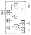
- FIG. 7 there is illustrated a general block diagram for a virtual private network unit 700.
- the general architecture of the VPN Unit 700 is essentially that of a specially tailored personal computer (PC) apparatus architecture.
- the overall operation of the VPN Unit 700 is driven by a central processing unit (CPU) 705 which is coupled to communicate with the other components of the apparatus over a apparatus bus 710.
- the memory apparatus 720 is also illustrated as residing on the apparatus bus 710.
- Those of ordinary skill in the art will of course recognize that various memory configurations may be implemented, some of which may include a dedicated memory bus for higher speed throughput to the memory apparatus 720.
- the VPN Unit 700 is designed to be an intermediate device between a site's local area network and the Internet or other public network space.
- the VPN Unit 700 is illustrated as having an I/O controller 730 for coupling the VPN Unit 700 to the Internet or other public network space.
- an I/O controller 740 is provided for coupling the VPN Unit 700 to the site's edge router.
- the VPN Unit 700 resides between the site's router and the Internet.
- the I/O controller 740 is responsible for data packet transmissions between the router for the site and the VPN Unit 700.
- the VPN Unit 700 may be disposed between a site's local area network and its router, in which case the I/O controller 730 would be responsible for data packet transmissions between the VPN Unit 700 and the router, while the I/O controller 740 would effectively be the VPN Unit's interface to the local area network.
- data packet transmissions would probably have to be handled in accordance with the network protocol standard of the local area network rather than the public network space IP transmissions as described above.
- the general architecture for VPN Unit 700 illustrates that the two I/O controllers 730 and 740 are coupled to communicate over the apparatus bus 710 through I/O control logic 750.
- the I/O control logic 750 is responsible for arbitrating access to the apparatus bus for the data packets coming in and going out, and for assuring the necessary throughput for the data connections.
- the determination with respect to one embodiment requires interrogation of a look-up table, which maintains the identities of the various VPN groups serviced by the VPN Unit 700, as well as the group members and the various processing parameters for data packets that are exchanged between group members.
- this interrogation may be handled by the CPU 705 with reference to look-up tables that would be maintained in the memory apparatus 720.
- the VPN Unit 700 architecture includes a compression engine 760, coupled to communicate with the rest of the apparatus over the apparatus bus 710, and an encryption engine 770 similarly coupled to the apparatus bus 710.
- a compression engine 760 coupled to communicate with the rest of the apparatus over the apparatus bus 710
- an encryption engine 770 similarly coupled to the apparatus bus 710.
- processing may be carried out by the CPU 705 with packets being assembled within the CPU 705 or at specified memory locations in the memory apparatus 720.
- logic may be incorporated in the VPN Unit 700 designed specifically for the support of such key management protocols or other packet processing operations.
- I/O devices 780 may be interfaced to the VPN Unit 700 through I/O control logic 790. This may facilitate management of the unit either by allowing direct keyboard access to control the processor, or provide a connection path for other communications devices which may need to communicate with the VPN Unit 700.
- VPN Unit 800 an architecture is disclosed which is driven by microprocessor 805, a 100 MHz Intel 486 DX4.
- the apparatus bus for this configuration is the VSIA bus 810 to which the other components of the apparatus are coupled.
- the memory apparatus in this case is supplied by several banks of fast dynamic random access memory (DRAM) 820.
- DRAM fast dynamic random access memory
- a PC chip set implementation from the Opti Corporation is provided at 825 for controlling the overall operation of the apparatus.
- the Opti chip set, as well as providing a apparatus controller functionality for the 486 DX4 microprocessor, may also be utilized to provide an interface to an optional ISA bus 828 to which other peripherals may be coupled to the apparatus.
- the I/O connections to the public network space 830 are provided by a series of multi-protocol transceivers with a DB-25 connector. Similarly, the connections for the private network side of the unit are provided through additional multi-protocol transceivers and an additional DB-25 connector.
- the I/O connections to the public and private networks are handled through a dual-port SCC 845 which includes a plurality of input and output buffers for transmission and receipt of data packets to the VPN Unit 800.
- the data packet I/O controller is coupled to the VSIA bus 810 through FPGA Control and Glue Logic 850.
- the compression engine for the implemented VPN Unit 800 is provided by an implementation of the STAC compression algorithm using the STAC chip 9710 compression engine 860, which is coupled to a dedicated bank of SRAM 865 to support its processing.
- the encryption engine is provided by a DES engine 870, which may be implemented in either an off-the-shelf special integrated circuit configuration or one designed to operate in accordance with the operation of the VPN Unit 800.
- the compression engine and encryption engine could be handled by software routines running on the microprocessor 805 or other general-purpose processing logic.
- Other alternative embodiments may use later generations of microprocessors which operate at higher speeds and may require implementation of a different apparatus bus such as the emerging PCI bus standard.
- Those of ordinary skill in the art will recognize alternative and various embodiments which may be designed to suit a particular purpose.
Abstract
Description
- The present invention is related to the one described in U.S. Patent application entitled " Architecture for Virtual Private Networks" Serial Number 08/874,090, assigned to the assignee of the present invention and filed concurrently herewith, corresponding to EP 0 988 735 A published on 29.03.2000.
- The present invention relates to the field of data communications. More particularly, the present invention relates to techniques for implementing secure virtual private networks over public or otherwise insecure data communications infrastructures.
- In recent years organizations have come to rely heavily on the ability to transmit electronic data between members of the organization. Such data typically includes electronic mail and file sharing or file transfer. In a centralized, single site organization, these transfers of electronic data are most commonly facilitated by a local area network (LAN) installed and operated by the particular enterprise.
- Preventing unauthorized access to data traversing an enterprise's LAN is relatively straightforward. This applies to both unauthorized accesses by members of the enterprise and, more importantly, to third parties on the outside. As long as intelligent network management is maintained, unauthorized accesses to data traversing an enterprise's internal LAN are relatively easily avoided. It is when the enterprise spans multiple sites that security threats from the outside become a major concern.
- For distributed enterprises that desire the conveniences of the above-described electronic data transfers, there are several options that exist today, but each with associated disadvantages. The first option is to interconnect the offices or various sites with dedicated, or private communications connections often referred to as leased lines. This is the traditional method organizations use to implement a wide area network (WAN). The disadvantages of implementing an enterprise owned and controlled WAN are obvious: they are expensive, cumbersome and frequently underutilized if they are established to handle the peak capacity requirements of the enterprise. The obvious advantage to this approach is that the lines are dedicated for use by the enterprise and are therefore secure, or reasonably secure from eavesdropping or tampering by intermediate third parties.
- An alternative to the use of dedicated communications lines in a wide area network is for an enterprise to handle intersite data distributions over the emerging public network space. Over recent years, the Internet has transitioned from being primarily a tool for scientists and academics to a mechanism for global communications with broad ranging business implications. The Internet provides electronic communications paths between millions of computers by interconnecting the various networks upon which those computers reside. It has become commonplace, even routine, for enterprises, even those in nontechnical fields, to provide Internet access to at least some portion of the computers within the enterprise. For many businesses this facilitates communications with customers, potential business partners as well as the distributed members of the organization.
- Distributed enterprises have found that the Internet is a convenient tool to provide electronic communications between members of the enterprise. For example, two remote sites within the enterprise may each connect to the Internet through a local Internet Service Provider (ISP). This enables the various members of the enterprise to communicate with other sites on the Internet including those within their own organization. The limiting disadvantage of using the Internet for intra-enterprise communications is that the Internet is a public network space. The route by which data communication travel from point to point can vary on a per packet basis, and is essentially indeterminate. Further, the data protocols for transmitting information over the various networks of the Internet are widely known, and leave electronic communications susceptible to interception and eavesdropping with packets being replicated at most intermediate hops. An even greater concern arises when it is realized that communications can be modified in transit or even initiated by impostors. With these disconcerting risks, most enterprises are unwilling to subject their proprietary and confidential internal communications to the exposure of the public network space. For many organizations it is common today to not only have Internet access provided at each site, but also to maintain the existing dedicated communications paths for internal enterprise communications, with all of the attendant disadvantages described above.
- While various encryption and other protection mechanisms have been developed for data communications, none completely and adequately addresses the concerns raised for allowing an enterprise to truly rely on the public network space for secure intra-enterprise data communications. It would be desirable, and is therefore an object of the present invention to provide such mechanisms which would allow the distributed enterprise to rely solely on the public network space for intra-enterprise communications without concern for security risks that presently exist.
- WO 97/00471 discloses a virtual private network unit according to the preamble of
claim 1. - From the foregoing it can be seen that it would be desirable and advantageous to develop protocols and architecture to allow a single organization or enterprise to rely on the public network space for secure intraorganizational electronic data communications. The present invention is thus directed toward the protocols and architecture for implementing secure virtual private networks over the Internet or other public network apparatus. The architecture of the present invention introduces a site protector or virtual private network (VPN) unit which moderates data communications between members of a defined VPN group. In accordance with one embodiment of the present invention, the site protector resides on the WAN side of the site's router or routing apparatus which is used to connect the enterprise site to the Internet. In alternative embodiments, the site protector will reside on the LAN side of the router. The essential point for all embodiments is that the site protector be in the path of all relevant data traffic.
- To ensure secure data communications between members of the same VPN group, the site protector or VPN Unit implements a combination of techniques for data packet handling when packets are to be sent between members of the group. The packet handling processes include various combinations of compression, encryption and authentication, the rules for each of which may vary for members of different groups. For each group defined as a virtual private network, the various parameters defining the compression, encryption and authentication are maintained in lookup tables in the associated VPN Units. The lookup tables maintain information not only for fixed address members of the group but support is also provided for remote clients. This ability allows remote users to dial into a local Internet Service Provider and still maintain membership in a virtual private network group for secure communications over the Internet with other members of the group. In the case of a remote client, the site protector may, in one embodiment, be simulated by software running on the remote client.
- In other aspects of the present invention, the VPN Units or site protectors may be dynamically configured to add or subtract members from the virtual private network group or recognize their movement, or change other parameters affecting the group. Various other packet handling aspects of the invention include addressing the problem of some data packets growing too large by the inclusion of encryption and authentication information. Another packet handling aspect provides a mechanism for Internet communications which hides information identifying the source and destination of the data packet. In this aspect of the present invention, the VPN Units are treated as the source and destination for the Internet communication data packets with the VPN Units encapsulating the source and destination addresses of the endstations.
- There is also disclosed a hardware architecture and implementation for a VPN Unit. This embodiment is one designed to reside on the WAN side of a given site's router. In the illustrated embodiment, a combination of computer hardware and software are provided for carrying out the processes of the VPN apparatus for compression, encryption and authentication under the direction of a microprocessor.
- The objects, features and advantages of the present invention will be apparent from the following detailed description, in which:
- Figure 1 illustrates a prior art configuration for an exemplary enterprise's intraenterprise communication architecture.
- Figure 2 illustrates an enterprise communication scenario in accordance with the present invention utilizing the Internet or other public network space as the vehicle for conveying messages between members of a virtual private network.
- Figure 3 illustrates a flow diagram for the handling of a packet being transmitted from one member of a virtual private network group to another member over the Internet.
- Figure 4 illustrates the handling of a data packet received over the Internet by one member of a virtual private network group from another member.
- Figure 5 illustrates graphically the life cycle of a data packet being sent from one member of a virtual private network group to another over the Internet.
- Figure 6 illustrates an alternate life cycle of a data packet being sent from one member of a virtual private network group to another over the Internet where the source and destination addresses of the group members are also concealed.
- Figure 7 illustrates an architectural block diagram for an implementation of a virtual private network unit in accordance with one embodiment of the present invention.
- Figure 8 illustrates a more detailed block diagram for one implementation of a virtual private network unit in accordance with one embodiment of the present invention.
- A virtual private network unit is disclosed for implementing secure virtual private networks for enterprise communications over the Internet or other public network space. Although the present invention is described predominantly in terms of utilizing the Internet as a communications medium, the concepts and methods are broad enough to accomplish the implementation of secure virtual private networks over other public or insecure communications media. Throughout this detailed description, numerous specific details are set forth such as particular encryption or key management protocols, in order to provide a thorough understanding of the present invention. To one skilled in the art, however, it will be understood that the present invention may be practiced without such specific details. In other instances, well-known control structures and apparatus components have not been shown in detail in order not to obscure the present invention.
- In many instances, components implemented by the present invention are described at an architectural, functional level. Many of the elements may be configured using well-known structures, particularly those designated as relating to various compression or encryption techniques. Additionally, for logic to be included within the apparatus of the present invention, functionality and flow diagrams are described in such a manner that those of ordinary skill in the art will be able to implement the particular methods without undue experimentation. It should also be understood that the techniques of the present invention may be implemented using a variety of technologies. For example, the virtual private network unit or site protector to be described further herein may be implemented in software running on a computer apparatus, or implemented in hardware utilizing either a combination of microprocessors or other specially designed application specific integrated circuits, programmable logic devices, or various combinations thereof. It will be understood by those skilled in the art that the present invention is not limited to any one particular implementation technique and those of ordinary skill in the art, once the functionality to be carried out by such components is described, will be able to implement the invention with various technologies without undue experimentation.
- Referring now to Figure 1 there is shown a traditional scenario for intra-enterprise data communications for a distributed organization. In this illustration of an exemplary organization configuration, the enterprise consists of a
headquarters location 105 with additional sites orbranches site 105 as well as thebranch sites communications lines 115 and 120 may be provided. In addition, an optionaldedicated communications path 125 may be provided between thebranches dedicated communications line 125 between the branches, data packets betweenbranch 110 andbranch 112 may be routed through the headquarters' network equipment. - In addition to the dedicated communications lines between the headquarters and the various branches, it is common today to provide computer users within an organization access to the Internet for electronic mail to external parties as well as for doing various types of research over the Internet using such tools as the World Wide Web, etc. As shown in Figure 1, the usual scenario where the headquarters'
site 105 and thebranches Internet Service Providers headquarters site 105 is provided with access to anInternet service provider 130 and that users of the computers of thebranch sites dedicated communications paths 115 and 120. The downside to this alternate configuration is that it greatly increases the bandwidth utilization on the dedicated lines, perhaps to the point of saturation. An advantage is that only one gateway to the Internet need be provided for the organization which simplifies enforcing security constraints on connections to the outside world. - In the
exemplary organization 100, it is also shown that in some circumstances it may be desirable to allow customers or other business partners to dial in directly to the computer network of the organization. In Figure 1 it is illustrated that thecustomer 140 may in fact carry out such communications over acommunications path 145 which may be a dedicated line provided between the customer and the organization for the customer's convenience. Thepath 145 may also be a dial-up line which the customer might use only sporadically. Consistent with the emerging use of the Internet and its popularity, thecustomer 140 is shown having its own Internet connection throughISP 148. - Finally, there is shown in Figure 1 that it is frequently desirable for other members of the enterprise who may be on the road or working from home or other remote locations to exchange data with other members of the enterprise. There is thus shown
remote clients distance telephone lines remote clients local ISPs - The above description of an enterprises data communications configuration according to Figure 1 illustrates the disadvantages described in the previous section. These disadvantages are eliminated by implementation of the present invention as illustrated generally with reference to Figure 2. In the enterprise
network communication configuration 200 illustrated in Figure 2, theheadquarters 105,first branch 110 andsecond branch 112 of the organization are illustrated in a more detailed logical way then presented in Figure 1. Thus, theheadquarters 105 is illustrated with threeendstations branch site 110 is shown having a plurality ofendstations LAN 215. Finally, thesecond branch site 112 is shown with an illustrative set ofcomputer stations LAN 225. Thecustomer site 140 is also illustrated in Figure 2 as comprising of plurality of computers illustrated by 331 and 332 coupled to communicate over the customer'sLAN 235. The local area networks utilized for data communications within the headquarters, customer and branch sites may adhere to a wide variety of network protocols, the most common of which are Ethernet and Token Ring. - As can be seen in Figure 2, the dedicated communications lines between the
headquarters site 105 and thebranch sites headquarters site 105 and thecustomers site 140 have been eliminated. Instead, in accordance with the present invention data communications between members of the organization are intended to be carried out over the Internet or other public network space. For purposes of the present invention, it will be assumed that it is the widely emerging Internet that will be the medium for data packet transfers between members of the organization. - Each of the LANs for the particular sites illustrated in Figure 2 ultimately interconnect to the
Internet 250 through an associated routing or gateway device which are identified asrouters remote clients Internet 250. - As has been described above, prior efforts to utilize the Internet for secure data communications have required an awareness or implementation of security considerations at the endstations. This is disadvantageous when transparency to an end user is desirable. The present invention, on the other hand is transparent to end users with data communications over the Internet occurring exactly as they appear to have before. However, for users identified as members of the same virtual private network, data communications are handled in a manner that assures the security and integrity of the data packets. Illustrated in Figure 2, between the
Internet 250 and each of therespective routers - When a data packet is sent between source and destination addresses that are both members of the same VPN group, the VPN Unit will process the data packet from the sending side in such a way as to ensure that it encrypted, authenticated and optionally compressed. Likewise, the VPN Unit servicing the site where the destination address is located will detect that a packet is being propagated between members of the same VPN group. The receiving VPN Unit will handle the process of decrypting and authenticating the packet before forwarding it toward the destination endstation. In this way, secure data communications between end users is effected in a manner that is transparent to the end users. In the case of
remote clients - The functionality of the VPN Units will be described with reference to the following figures beginning with the flowchart of Figure 3. When a data packet originates from an endstation, such as
endstation 202 ofLAN 205 atsite 105, and its destination is to a remote site, other than theheadquarters site 105, it will initially be treated as an ordinary Internet data packet transfer. The packet will proceed from theendstation 202 over theLAN 205 to therouting device 240 which will encapsulate the data packet in accordance with the Internet Protocol, forming an outbound IP packet. On its way out of the site, the IP packet will pass through the associated VPN Unit for the site. The flowchart illustrated at Figure 3 shows the functional operation of a VPN Unit for an outbound packet that is received thereby. The TransmitPacket procedure 300 begins when the outbound data packet is received at the VPN Unit atstep 310. At decision box 320, it is determined whether or not the source and destination addresses for the data packet are both members of the same VPN group. This determination may be made with reference to lookup tables that are maintained by the VPN Units or reference to other memory mechanisms. This step may be thought of as member filtering for data packets being transmitted between the particular site and the VPN Unit which services it. If the source and destination address for the data packet are not both members of the same VPN group, then atstep 330 the packet is forwarded to the Internet as ordinary Internet traffic from the site as though the VPN Unit were not involved. In which case, the procedure ends atstep 335. In one alternative embodiment, it may be desirable to discard data traffic that is not destined between members of a VPN group rather than forwarding it as unsecure traffic. In another alternative embodiment, it may be desirable to provide the option to either pass or discard non-VPN-group data traffic. - If, at decision box 320, the member filter, it is determined that both the source and destination addresses for the data packet are members of the same VPN group, then the data packet is processed at
step 340 undergoing various combinations of compression, encryption and authentication. The lookup tables maintained by theVPN Unit 250 and all of the VPN Units, in addition to identifying members of particular VPN groups, also identify whether or not data packets transferred between members of the particular VPN group are to be compressed and if so, what algorithm is to be used for compression. Many possible compression algorithms are well-known, but in one embodiment of the invention, LZW compression is implemented. The lookup table for the VPN group of which the source and destination addresses are members also identifies the particular encryption algorithm to be used for data packets traversing the Internet for that VPN group as well as the authentication and key management protocol information to be used thereby. As an alternative to lookup tables, the VPN Unit may be programmed to always use the same algorithms for all VPN groups. - The particular packet processing algorithms to be used for VPN traffic may vary, so long as the lookup tables in both the sending and receiving VPN Units identify the same compression, encryption and authentication rules and are capable of implementing and deimplementing them for members of the same group. It is to be understood that a single VPN Unit may serve multiple VPN groups and that particular addresses may be members of multiple groups. Thus, at
step 340, when a packet is destined from one member of the VPN group to another, the packet is processed according to the compression, encryption and authentication rules identified in the VPN Unit tables for that particular VPN group. Then, atstep 350, the processed packet is forwarded toward the destination address over the Internet. The procedure of the sending VPN Unit then ends atstep 355. - The receiving VPN Unit reverses the above processes for VPN traffic as illustrated by the flowchart of Figure 4. The Receive
Packet procedure 400 begins at step 410 when an inbound data packet is received from the Internet at the receiving VPN Unit. At decision box 420, the inbound data packet is examined to determine if the source and destination addresses of the data packet are both members of the same VPN group. It is assumed that the lookup tables maintained by all of the VPN Units are both consistent and coherent. If the inbound data packet is determined not to be VPN traffic, then the packet is passed through and forwarded to the receiving site as though it were normal Internet data traffic atstep 430. In which case the process ends atstep 435. In one alternative embodiment it may be desirable to discard incoming data traffic that is not from an identified member of a VPN group supported by the VPNU. - For data packets that are determined to be VPN traffic at decision box 420, the VPN Unit will process the inbound packet to recover the original data packet as it was provided from the source endstation. The lookup table maintained by the receiving VPN Unit will identify the compression, encryption and authentication rules used for the VPN group and reconstruct the original IP packet in accordance with those rules at
step 440. Then, the reconstructed packet will be delivered to the site of the destination address at 450 with the procedure ending atstep 455. - Figure 5 illustrates graphically the life cycle of the data packet sent between two members of the same VPN group. The data packet originates from a
source 500 and propagates from the sources site through its associated router to generateIP data packet 510. Thedata packet 510 is not intended to illustrate all the fields associated with a complete IP data packet, but shows the relevant portions for this discussion which include the destination address, source address and the payload information of the packet. Thedata packet 510 is then examined by the VPN Unit which determines whether the data packet is traffic between members of an identified VPN group. TheVPN Unit 520 processes the packet in accordance with the packet processing procedures described above with respect to Figure 3 with the resulting packet being illustrated aspacket 530.Packet 530 still identifies the destination and source addresses of the data packet, but the remainder of the packet is encrypted, and optionally compressed. - Following processing by the outbound VPN Unit, the data packet is propagated through the Internet to 550 with the destination and source information identifying to the associated routers of the Internet the path by which the packet should ultimately take to reach its destination. The packet emerges from the Internet at the edge of the destination site as
data packet 540 which is essentially identical to thedata packet 530. The packet is "deprocessed" by the receivingVPN Unit 550 which restores the original packet into itsform 560 for delivery to the ultimate destination through the receiving site's associated router at destination 570. - As was described above, the present invention approach to virtual private networks supports not only optional compression of data packets, but encryption and authentication techniques as well. One emerging standard for key management in connection with Internet Protocol data transfers with authentication is referred to as simple key management for Internet Protocol (SKIP) which is described by US Patent 5,588,060 assigned to Sun Microapparatus, Inc. of Mountain View, CA. Authenticated data transfers using SKIP support a mode of data transfer referred to as tunnel mode. The above described data transfer with respect to Figure 5 illustrates a transport mode of operation in which the data and source addresses are exposed as the data packet traverses the Internet. In tunnel mode, an added measure of security may be provided by encapsulating the entire data packet in another packet which identifies the source and destination addresses only for the VPN Units. This conceals the ultimate source and destination addresses in transit.
- Figure 6 illustrates the life cycle of a data packet being propagated from a
source 600 to adestination 670 utilizing tunnel mode. In this mode of operation, thedata packet 610 is processed by outbound VPN Unit 620 which generates a resulting packet 630. The resulting packet 630 encrypts and compresses (optionally) not only the data payload of the packet, but the destination and source addresses of the endstations as well. The encapsulated packet is then provided with an additional header that identifies that the source of the packet is the outbound VPN Unit 620 and that the destination is theinbound VPN Unit 650. Thus, thepacket 640 which emerges from the Internet is identical to the packet 630 with respect to its source and address information and encapsulated payload. The packet is decomposed by theinbound VPN Unit 650 to reconstruct the original data packet at 660 for delivery to thedestination 670. - The overall architecture of the present invention is robust. It allows end users the convenience of proprietary data communications to take place over a public network space such as the Internet. The architecture of the present invention also allows a wide variety of compression, encryption and authentication technologies to be implemented, so long as the VPN Units at each end of the transaction support the associated protocols. The present invention is also capable of working in concert with traditional Internet security mechanisms such as corporate firewalls. A firewall might operate in series with the VPN Unit at a given site, or, intelligently be configured in a single box with the VPN Unit to provide parallel firewall and VPN Unit security functions.
- The above discussion relates to the functionality for implementing virtual private networks. There is now described a hardware architecture and implementation for a virtual private network unit in accordance with one embodiment of the present invention. Referring now to Figure 7 there is illustrated a general block diagram for a virtual
private network unit 700. The general architecture of theVPN Unit 700 is essentially that of a specially tailored personal computer (PC) apparatus architecture. The overall operation of theVPN Unit 700 is driven by a central processing unit (CPU) 705 which is coupled to communicate with the other components of the apparatus over a apparatus bus 710. In the general architecture illustrated forVPN Unit 700, thememory apparatus 720 is also illustrated as residing on the apparatus bus 710. Those of ordinary skill in the art will of course recognize that various memory configurations may be implemented, some of which may include a dedicated memory bus for higher speed throughput to thememory apparatus 720. - The
VPN Unit 700 is designed to be an intermediate device between a site's local area network and the Internet or other public network space. Thus, theVPN Unit 700 is illustrated as having an I/O controller 730 for coupling theVPN Unit 700 to the Internet or other public network space. Similarly, an I/O controller 740 is provided for coupling theVPN Unit 700 to the site's edge router. In accordance with the above-described functional requirements, theVPN Unit 700 resides between the site's router and the Internet. In this implementation, the I/O controller 740 is responsible for data packet transmissions between the router for the site and theVPN Unit 700. In an alternate embodiment of the present invention, theVPN Unit 700 may be disposed between a site's local area network and its router, in which case the I/O controller 730 would be responsible for data packet transmissions between theVPN Unit 700 and the router, while the I/O controller 740 would effectively be the VPN Unit's interface to the local area network. In this alternative embodiment, data packet transmissions would probably have to be handled in accordance with the network protocol standard of the local area network rather than the public network space IP transmissions as described above. In either event, the general architecture forVPN Unit 700 illustrates that the two I/O controllers O control logic 750. In accordance with this architecture, the I/O control logic 750 is responsible for arbitrating access to the apparatus bus for the data packets coming in and going out, and for assuring the necessary throughput for the data connections. - As has been described, when a data packet is received at the
VPN Unit 700, whether outbound or inbound, a determination is made by examining the data packet's header as to whether or not both the source and destination addresses represent members of the same VPN group. The determination with respect to one embodiment requires interrogation of a look-up table, which maintains the identities of the various VPN groups serviced by theVPN Unit 700, as well as the group members and the various processing parameters for data packets that are exchanged between group members. In accordance with the general architecture of theVPN Unit 700, this interrogation may be handled by theCPU 705 with reference to look-up tables that would be maintained in thememory apparatus 720. - For data packets that are to be processed as packets being sent between members of a supported VPN group, it has been described that compression and decompression functions as well as encryption and decryption functions need to be performed for such data. Thus, the
VPN Unit 700 architecture includes acompression engine 760, coupled to communicate with the rest of the apparatus over the apparatus bus 710, and anencryption engine 770 similarly coupled to the apparatus bus 710. For supporting functions such as the various key management protocols described above which result in the generation of packet encapsulation headers, processing may be carried out by theCPU 705 with packets being assembled within theCPU 705 or at specified memory locations in thememory apparatus 720. Alternatively, logic may be incorporated in theVPN Unit 700 designed specifically for the support of such key management protocols or other packet processing operations. - There is finally shown in the
VPN Unit 700 architecture that optional I/O devices 780 may be interfaced to theVPN Unit 700 through I/O control logic 790. This may facilitate management of the unit either by allowing direct keyboard access to control the processor, or provide a connection path for other communications devices which may need to communicate with theVPN Unit 700. - Referring now to Figure 8, there is illustrated a more detailed block diagram for one implementation of a VPN Unit in accordance with one embodiment of the present invention. In the implemented embodiment of
VPN Unit 800 an architecture is disclosed which is driven bymicroprocessor 805, a 100 MHz Intel 486 DX4. The apparatus bus for this configuration is the VSIA bus 810 to which the other components of the apparatus are coupled. The memory apparatus in this case is supplied by several banks of fast dynamic random access memory (DRAM) 820. In accordance with this implemented embodiment, a PC chip set implementation from the Opti Corporation is provided at 825 for controlling the overall operation of the apparatus. The Opti chip set, as well as providing a apparatus controller functionality for the 486 DX4 microprocessor, may also be utilized to provide an interface to anoptional ISA bus 828 to which other peripherals may be coupled to the apparatus. - In the implemented
VPN Unit 800, the I/O connections to thepublic network space 830 are provided by a series of multi-protocol transceivers with a DB-25 connector. Similarly, the connections for the private network side of the unit are provided through additional multi-protocol transceivers and an additional DB-25 connector. The I/O connections to the public and private networks are handled through a dual-port SCC 845 which includes a plurality of input and output buffers for transmission and receipt of data packets to theVPN Unit 800. The data packet I/O controller is coupled to the VSIA bus 810 through FPGA Control andGlue Logic 850. - The compression engine for the implemented
VPN Unit 800 is provided by an implementation of the STAC compression algorithm using theSTAC chip 9710compression engine 860, which is coupled to a dedicated bank ofSRAM 865 to support its processing. Finally, in the implemented embodiment the encryption engine is provided by a DES engine 870, which may be implemented in either an off-the-shelf special integrated circuit configuration or one designed to operate in accordance with the operation of theVPN Unit 800. In accordance with an alternative embodiment of the present invention, it is conceivable that the compression engine and encryption engine could be handled by software routines running on themicroprocessor 805 or other general-purpose processing logic. Other alternative embodiments may use later generations of microprocessors which operate at higher speeds and may require implementation of a different apparatus bus such as the emerging PCI bus standard. Those of ordinary skill in the art will recognize alternative and various embodiments which may be designed to suit a particular purpose. - There has thus been described a protocol and architecture for implementing virtual private networks for using a public network space for secure private network data communications. Although the present invention has been described with respect to certain exemplary and implemented embodiments, it should be understood that those of ordinary skill in the art will readily appreciate various alternatives to the present invention. Accordingly, the scope of the present invention should be measured by the terms of the claims.
Claims (14)
- A virtual private network unit for providing secured data communications between members of a virtual private network group comprising:input/output (I/O) circuitry (730, 740) for receiving and transmitting data packets between the members (201, 202, 203, 211, 212, 213, 331, 332, 150, 155) of the virtual private network group over a public network (250);a system bus (710) in communication with said I/O circuitry for conveying data between components of said virtual private network unit;a compression engine (760) in communication with said system bus for compressing outbound data packets and decompressing inbound data packets;an encryption engine (770) in communication with said system bus for encrypting outbound data packets and decrypting inbound data packets;a central processing unit (CPU) (705) in communication with said system bus for controlling the processing of data packets by said virtual private network unit; anda memory (720) in communication with said system bus,characterized in that:said memory (720) is adapted to maintain a list of members of the virtual private network group and store predetermined parameters; andsaid CPU (705) is adapted to discriminate on the basis of said list of members between data packets being sent between members of the virtual private network group and data packets being sent between a member of the virtual private network group and a non-member of the virtual private network group, wherein,when the data packets are determined as being sent between two members of the virtual private network group, the data packets will be on the basis of said predetermined parameters, encrypted by said encryption engine (770) and optionally compressed by said compression engine (760), andwhen the data packets are determined as not being sent between two members of the virtual private network group, the data packets will be treated as ordinary internet traffic.
- The virtual private network unit according to claim 1, wherein said virtual private network unit is a first virtual private network unit, and further comprising:a first computer (211) at a first site, said first computer having a first network address;a first router (242) associated with said first site for routing data packets originating from said first computer over the network (250);wherein said first virtual private network unit (252) is disposed between said first router and the network, said first virtual private network unit being adapted to identify virtual private network group data traffic and secure the data traffic by manipulating the data traffic;
a second router (244) associated with a second site for coupling said second site to the network;
a second virtual private network unit (254) identical in structure to said first virtual private network unit, wherein said second virtual private network unit is disposed between said second router and the network for intercepting network traffic destined for said second site, said second virtual private network unit for detecting virtual private network group traffic and for recovering original packet data; and
a second computer (221) at said second site, said second computer having a second network address for receiving the data packets. - The virtual private network unit according to claim 1, wherein said virtual private network unit is a first virtual private network unit, and further comprising:a first computer (211) at a first site, said first computer having a first network address;a first router (242) associated with said first site for routing data packets originating from said first computer over the network (250);wherein said first virtual private network unit (252) is disposed between said first router (242) and said first computer (211), said first virtual private network unit being adapted to identify virtual private network group data traffic and secures the data traffic by manipulating the data traffic;
a second router (244) associated with a second site for coupling said second site to the network;
a second computer (221) at said second site, said second computer having a second network address for receiving said data packets; and
a second virtual private network unit (254) identical in structure to said first virtual private network unit, wherein said second virtual private network unit is disposed between said second router (244) and said second computer (221) for intercepting network traffic destined for said second site, said second virtual private network unit for detecting virtual private network group traffic and for recovering original data packets. - The virtual private network unit according to any of the preceding claims, wherein said memory (720) is also adapted to store transmission parameters associated with members of the virtual private network group, and wherein the transmission parameters dictate whether a data packet transmission to/from a particular member of the virtual private network group requires compression/decompression and/or encryption/decryption.
- The virtual private network unit according to claim 4, wherein said compression engine (760) and said encryption engine (770) includes circuitry or software for generating and confirming an authentication code associated with outgoing and incoming data packets, respectively.
- The virtual private network unit according to claim 5, wherein said transmission parameters associated with members of the virtual private network group also specify whether or not authentication is required of the communicated data packets transmitted to/from the associated member of the virtual private network group.
- The virtual private network unit according to one of the preceding claims, wherein the network is the Internet (250).
- The virtual private network unit according to one of the preceding claims, wherein said I/O circuitry comprises:a private I/O port (740) for coupling said virtual private network unit to a site's private network;a public I/O port (730) for coupling said virtual private network unit to the network (250); andI/O control logic (750) in communication with said system bus (710) and coupled to said private and public I/O ports for controlling data packet flow between said virtual private network unit and members of the virtual private network group.
- The virtual private network unit according to one of the preceding claims, wherein said CPU (705) generates encapsulation headers for outbound data packets in accordance with a key management protocol.
- The virtual private network unit according to claim 9, wherein the key management protocol includes the Simple Key Management for Internet Protocol (SKIP).
- The virtual private network unit according to one of the preceding claims, wherein said compression engine (760) and said encryption engine (770) includes circuitry or software for performing DES encryption or triple-DES encryption in accordance with said predetermined parameters.
- The virtual private network unit according to one of the preceding claims, wherein said compression engine (760) and said encryption engine (770) includes circuitry or software for performing LZW compression.
- The virtual private network unit according to one of the preceding claims, wherein said memory (720) comprises lookup tables for identifying all the virtual private network groups and the members of the groups, wherein the members are each identified by a network address and wherein a single network address may identify a member as belonging to multiple virtual private network groups.
- The virtual private network unit according to one of the preceding claims, wherein when the data packets are determined as being sent between a member of the virtual private network group and a non-member of the virtual private network group, the data packets will not be compressed and will not be encrypted.
Applications Claiming Priority (3)
| Application Number | Priority Date | Filing Date | Title |
|---|---|---|---|
| US08/874,091 US6173399B1 (en) | 1997-06-12 | 1997-06-12 | Apparatus for implementing virtual private networks |
| US874091 | 1997-06-12 | ||
| PCT/US1998/012226 WO1998057464A1 (en) | 1997-06-12 | 1998-06-11 | An apparatus for implementing virtual private networks |
Publications (2)
| Publication Number | Publication Date |
|---|---|
| EP0988736A1 EP0988736A1 (en) | 2000-03-29 |
| EP0988736B1 true EP0988736B1 (en) | 2007-02-28 |
Family
ID=25362958
Family Applications (1)
| Application Number | Title | Priority Date | Filing Date |
|---|---|---|---|
| EP98929021A Expired - Lifetime EP0988736B1 (en) | 1997-06-12 | 1998-06-11 | An apparatus for implementing virtual private networks |
Country Status (9)
| Country | Link |
|---|---|
| US (1) | US6173399B1 (en) |
| EP (1) | EP0988736B1 (en) |
| JP (1) | JP2002504285A (en) |
| KR (1) | KR100431956B1 (en) |
| AT (1) | ATE355684T1 (en) |
| AU (1) | AU8068498A (en) |
| CA (1) | CA2293435C (en) |
| DE (1) | DE69837201T2 (en) |
| WO (1) | WO1998057464A1 (en) |
Families Citing this family (203)
| Publication number | Priority date | Publication date | Assignee | Title |
|---|---|---|---|---|
| FR2761843B1 (en) * | 1997-03-12 | 2002-05-03 | Mannesmann Ag | METHOD FOR OPERATING PRIVATE VIRTUAL NETWORKS IN A COMMON NETWORK FOR SWITCHING DATA PACKETS AND DEVICE FOR CARRYING OUT SAID METHOD |
| US6226748B1 (en) * | 1997-06-12 | 2001-05-01 | Vpnet Technologies, Inc. | Architecture for virtual private networks |
| US6112239A (en) * | 1997-06-18 | 2000-08-29 | Intervu, Inc | System and method for server-side optimization of data delivery on a distributed computer network |
| CA2217275C (en) * | 1997-10-03 | 2005-08-16 | Newbridge Networks Corporation | Multiple internetworking realms within an internetworking device |
| USRE42761E1 (en) | 1997-12-31 | 2011-09-27 | Crossroads Systems, Inc. | Storage router and method for providing virtual local storage |
| US5941972A (en) * | 1997-12-31 | 1999-08-24 | Crossroads Systems, Inc. | Storage router and method for providing virtual local storage |
| US6226751B1 (en) * | 1998-04-17 | 2001-05-01 | Vpnet Technologies, Inc. | Method and apparatus for configuring a virtual private network |
| US7095740B1 (en) * | 1998-06-30 | 2006-08-22 | Nortel Networks Limited | Method and apparatus for virtual overlay networks |
| US6751729B1 (en) * | 1998-07-24 | 2004-06-15 | Spatial Adventures, Inc. | Automated operation and security system for virtual private networks |
| US6765919B1 (en) * | 1998-10-23 | 2004-07-20 | Brocade Communications Systems, Inc. | Method and system for creating and implementing zones within a fibre channel system |
| US10511573B2 (en) | 1998-10-30 | 2019-12-17 | Virnetx, Inc. | Agile network protocol for secure communications using secure domain names |
| EP1125419B1 (en) | 1998-10-30 | 2009-08-26 | VirnetX Inc. | An agile network protocol for secure communications with assured system availability |
| US6502135B1 (en) | 1998-10-30 | 2002-12-31 | Science Applications International Corporation | Agile network protocol for secure communications with assured system availability |
| US6826616B2 (en) | 1998-10-30 | 2004-11-30 | Science Applications International Corp. | Method for establishing secure communication link between computers of virtual private network |
| US7418504B2 (en) | 1998-10-30 | 2008-08-26 | Virnetx, Inc. | Agile network protocol for secure communications using secure domain names |
| US6321338B1 (en) | 1998-11-09 | 2001-11-20 | Sri International | Network surveillance |
| US6542508B1 (en) * | 1998-12-17 | 2003-04-01 | Watchguard Technologies, Inc. | Policy engine using stream classifier and policy binding database to associate data packet with appropriate action processor for processing without involvement of a host processor |
| US6636898B1 (en) * | 1999-01-29 | 2003-10-21 | International Business Machines Corporation | System and method for central management of connections in a virtual private network |
| US6901604B1 (en) * | 1999-02-19 | 2005-05-31 | Chaincast, Inc. | Method and system for ensuring continuous data flow between re-transmitters within a chaincast communication system |
| WO2000049755A2 (en) * | 1999-02-19 | 2000-08-24 | Nokia Networks Oy | Network arrangement for communication |
| US20020101998A1 (en) * | 1999-06-10 | 2002-08-01 | Chee-Hong Wong | Fast escrow delivery |
| US20020019932A1 (en) * | 1999-06-10 | 2002-02-14 | Eng-Whatt Toh | Cryptographically secure network |
| US6988199B2 (en) * | 2000-07-07 | 2006-01-17 | Message Secure | Secure and reliable document delivery |
| US6957346B1 (en) * | 1999-06-15 | 2005-10-18 | Ssh Communications Security Ltd. | Method and arrangement for providing security through network address translations using tunneling and compensations |
| GB2352370B (en) * | 1999-07-21 | 2003-09-03 | Int Computers Ltd | Migration from in-clear to encrypted working over a communications link |
| US6675225B1 (en) * | 1999-08-26 | 2004-01-06 | International Business Machines Corporation | Method and system for algorithm-based address-evading network snoop avoider |
| US7072964B1 (en) * | 1999-08-31 | 2006-07-04 | Science Applications International Corporation | System and method for interconnecting multiple virtual private networks |
| EP1222548A4 (en) * | 1999-08-31 | 2009-04-22 | Anxebusiness Corp | System and method for interconnecting multiple virtual private networks |
| US6693878B1 (en) * | 1999-10-15 | 2004-02-17 | Cisco Technology, Inc. | Technique and apparatus for using node ID as virtual private network (VPN) identifiers |
| US7117530B1 (en) * | 1999-12-07 | 2006-10-03 | Watchguard Technologies, Inc. | Tunnel designation system for virtual private networks |
| US6870842B1 (en) | 1999-12-10 | 2005-03-22 | Sun Microsystems, Inc. | Using multicasting to provide ethernet-like communication behavior to selected peers on a network |
| US7336790B1 (en) | 1999-12-10 | 2008-02-26 | Sun Microsystems Inc. | Decoupling access control from key management in a network |
| US6977929B1 (en) | 1999-12-10 | 2005-12-20 | Sun Microsystems, Inc. | Method and system for facilitating relocation of devices on a network |
| WO2001043356A2 (en) * | 1999-12-10 | 2001-06-14 | Sun Microsystems, Inc. | Sandboxing applications in a private network using a public-network infrastructure |
| WO2001045351A2 (en) * | 1999-12-10 | 2001-06-21 | Sun Microsystems, Inc. | Scalable security for groups in a virtual private network |
| US6970941B1 (en) | 1999-12-10 | 2005-11-29 | Sun Microsystems, Inc. | System and method for separating addresses from the delivery scheme in a virtual private network |
| US6938169B1 (en) | 1999-12-10 | 2005-08-30 | Sun Microsystems, Inc. | Channel-specific file system views in a private network using a public-network infrastructure |
| US7765581B1 (en) | 1999-12-10 | 2010-07-27 | Oracle America, Inc. | System and method for enabling scalable security in a virtual private network |
| US7130629B1 (en) | 2000-03-08 | 2006-10-31 | Cisco Technology, Inc. | Enabling services for multiple sessions using a single mobile node |
| US6286049B1 (en) * | 2000-03-24 | 2001-09-04 | Covad Communications Group, Inc. | System and method for providing broadband content to high-speed access subscribers |
| US7089240B2 (en) * | 2000-04-06 | 2006-08-08 | International Business Machines Corporation | Longest prefix match lookup using hash function |
| US7181542B2 (en) * | 2000-04-12 | 2007-02-20 | Corente, Inc. | Method and system for managing and configuring virtual private networks |
| US7047424B2 (en) * | 2000-04-12 | 2006-05-16 | Corente, Inc. | Methods and systems for hairpins in virtual networks |
| US7028334B2 (en) * | 2000-04-12 | 2006-04-11 | Corente, Inc. | Methods and systems for using names in virtual networks |
| US7085854B2 (en) * | 2000-04-12 | 2006-08-01 | Corente, Inc. | Methods and systems for enabling communication between a processor and a network operations center |
| US6996628B2 (en) * | 2000-04-12 | 2006-02-07 | Corente, Inc. | Methods and systems for managing virtual addresses for virtual networks |
| US7028333B2 (en) * | 2000-04-12 | 2006-04-11 | Corente, Inc. | Methods and systems for partners in virtual networks |
| US6631416B2 (en) | 2000-04-12 | 2003-10-07 | Openreach Inc. | Methods and systems for enabling a tunnel between two computers on a network |
| US7181766B2 (en) * | 2000-04-12 | 2007-02-20 | Corente, Inc. | Methods and system for providing network services using at least one processor interfacing a base network |
| US7069592B2 (en) | 2000-04-26 | 2006-06-27 | Ford Global Technologies, Llc | Web-based document system |
| WO2001082097A1 (en) * | 2000-04-27 | 2001-11-01 | Fortress Technologies, Inc. | A method and apparatus for integrating tunneling protocols with standard routing protocols |
| US7500143B2 (en) * | 2000-05-05 | 2009-03-03 | Computer Associates Think, Inc. | Systems and methods for managing and analyzing faults in computer networks |
| US7752024B2 (en) * | 2000-05-05 | 2010-07-06 | Computer Associates Think, Inc. | Systems and methods for constructing multi-layer topological models of computer networks |
| AU2001261275A1 (en) * | 2000-05-05 | 2001-11-20 | Aprisma Management Technologies, Inc. | Systems and methods for isolating faults in computer networks |
| US7237138B2 (en) * | 2000-05-05 | 2007-06-26 | Computer Associates Think, Inc. | Systems and methods for diagnosing faults in computer networks |
| AU2001261258A1 (en) * | 2000-05-05 | 2001-11-20 | Aprisma Management Technologies, Inc. | Help desk systems and methods for use with communications networks |
| US7251728B2 (en) | 2000-07-07 | 2007-07-31 | Message Secure Corporation | Secure and reliable document delivery using routing lists |
| US7111163B1 (en) | 2000-07-10 | 2006-09-19 | Alterwan, Inc. | Wide area network using internet with quality of service |
| US6772226B1 (en) * | 2000-08-15 | 2004-08-03 | Avaya Technology Corp. | VPN device clustering using a network flow switch and a different mac address for each VPN device in the cluster |
| US7111072B1 (en) | 2000-09-13 | 2006-09-19 | Cosine Communications, Inc. | Packet routing system and method |
| US7574495B1 (en) * | 2000-09-13 | 2009-08-11 | Fortinet, Inc. | System and method for managing interworking communications protocols |
| US8250357B2 (en) | 2000-09-13 | 2012-08-21 | Fortinet, Inc. | Tunnel interface for securing traffic over a network |
| US7272643B1 (en) | 2000-09-13 | 2007-09-18 | Fortinet, Inc. | System and method for managing and provisioning virtual routers |
| US7444398B1 (en) * | 2000-09-13 | 2008-10-28 | Fortinet, Inc. | System and method for delivering security services |
| US7174372B1 (en) | 2000-09-13 | 2007-02-06 | Fortinet, Inc. | System and method for managing router metadata |
| WO2002027503A1 (en) * | 2000-09-27 | 2002-04-04 | Sony Corporation | Home network system |
| US20020048372A1 (en) * | 2000-10-19 | 2002-04-25 | Eng-Whatt Toh | Universal signature object for digital data |
| AU3269001A (en) * | 2000-11-09 | 2002-05-21 | Accenture Llp | Communications system for supporting inter-dependent data messages |
| US6687700B1 (en) | 2000-11-09 | 2004-02-03 | Accenture Llp | Communications system for supporting inter-dependent data messages |
| US20040047347A1 (en) * | 2000-11-13 | 2004-03-11 | Michael Worry | Method, system and apparatus for reprogramming a digital electronic device via a computer network |
| US6894999B1 (en) * | 2000-11-17 | 2005-05-17 | Advanced Micro Devices, Inc. | Combining VLAN tagging with other network protocols allows a user to transfer data on a network with enhanced security |
| US7251824B2 (en) * | 2000-12-19 | 2007-07-31 | Intel Corporation | Accessing a private network |
| US8266677B2 (en) * | 2000-12-20 | 2012-09-11 | Intellisync Corporation | UDP communication with a programmer interface over wireless networks |
| US7159031B1 (en) * | 2001-01-26 | 2007-01-02 | Fortinet, Inc. | Remote customer management of virtual routers allocated to the customer |
| DE10107883B4 (en) * | 2001-02-19 | 2006-02-09 | Deutsche Post Ag | Method for transmitting data, proxy server and data transmission system |
| US20020161854A1 (en) * | 2001-03-06 | 2002-10-31 | Warren Wojcik | Digital city |
| US20030115480A1 (en) * | 2001-12-17 | 2003-06-19 | Worldcom, Inc. | System, method and apparatus that employ virtual private networks to resist IP QoS denial of service attacks |
| US7599351B2 (en) | 2001-03-20 | 2009-10-06 | Verizon Business Global Llc | Recursive query for communications network data |
| US6778498B2 (en) | 2001-03-20 | 2004-08-17 | Mci, Inc. | Virtual private network (VPN)-aware customer premises equipment (CPE) edge router |
| US7533409B2 (en) * | 2001-03-22 | 2009-05-12 | Corente, Inc. | Methods and systems for firewalling virtual private networks |
| US20020138635A1 (en) * | 2001-03-26 | 2002-09-26 | Nec Usa, Inc. | Multi-ISP controlled access to IP networks, based on third-party operated untrusted access stations |
| US20020144144A1 (en) * | 2001-03-27 | 2002-10-03 | Jeffrey Weiss | Method and system for common control of virtual private network devices |
| US20020143872A1 (en) * | 2001-03-27 | 2002-10-03 | Jeffrey Weiss | Multiple service management platform utilizing common directory |
| US7366194B2 (en) | 2001-04-18 | 2008-04-29 | Brocade Communications Systems, Inc. | Fibre channel zoning by logical unit number in hardware |
| US20020154635A1 (en) * | 2001-04-23 | 2002-10-24 | Sun Microsystems, Inc. | System and method for extending private networks onto public infrastructure using supernets |
| JP3945297B2 (en) * | 2001-04-24 | 2007-07-18 | 株式会社日立製作所 | System and management system |
| US7099912B2 (en) * | 2001-04-24 | 2006-08-29 | Hitachi, Ltd. | Integrated service management system |
| US7536715B2 (en) * | 2001-05-25 | 2009-05-19 | Secure Computing Corporation | Distributed firewall system and method |
| US20030078964A1 (en) * | 2001-06-04 | 2003-04-24 | Nct Group, Inc. | System and method for reducing the time to deliver information from a communications network to a user |
| US7194766B2 (en) | 2001-06-12 | 2007-03-20 | Corrent Corporation | Method and system for high-speed processing IPSec security protocol packets |
| US7047562B2 (en) * | 2001-06-21 | 2006-05-16 | Lockheed Martin Corporation | Conditioning of the execution of an executable program upon satisfaction of criteria |
| US7181547B1 (en) * | 2001-06-28 | 2007-02-20 | Fortinet, Inc. | Identifying nodes in a ring network |
| US7107464B2 (en) * | 2001-07-10 | 2006-09-12 | Telecom Italia S.P.A. | Virtual private network mechanism incorporating security association processor |
| US7827278B2 (en) * | 2001-07-23 | 2010-11-02 | At&T Intellectual Property Ii, L.P. | System for automated connection to virtual private networks related applications |
| US7827292B2 (en) * | 2001-07-23 | 2010-11-02 | At&T Intellectual Property Ii, L.P. | Flexible automated connection to virtual private networks |
| US8239531B1 (en) * | 2001-07-23 | 2012-08-07 | At&T Intellectual Property Ii, L.P. | Method and apparatus for connection to virtual private networks for secure transactions |
| US6662198B2 (en) | 2001-08-30 | 2003-12-09 | Zoteca Inc. | Method and system for asynchronous transmission, backup, distribution of data and file sharing |
| US6407673B1 (en) * | 2001-09-04 | 2002-06-18 | The Rail Network, Inc. | Transit vehicle multimedia broadcast system |
| US7036143B1 (en) | 2001-09-19 | 2006-04-25 | Cisco Technology, Inc. | Methods and apparatus for virtual private network based mobility |
| US7085827B2 (en) * | 2001-09-20 | 2006-08-01 | Hitachi, Ltd. | Integrated service management system for remote customer support |
| US7010608B2 (en) * | 2001-09-28 | 2006-03-07 | Intel Corporation | System and method for remotely accessing a home server while preserving end-to-end security |
| US7076797B2 (en) * | 2001-10-05 | 2006-07-11 | Microsoft Corporation | Granular authorization for network user sessions |
| AU2002340403A1 (en) * | 2001-11-16 | 2003-06-10 | Paralleldb, Incorporated | Data replication system and method |
| JP3885573B2 (en) | 2001-12-04 | 2007-02-21 | 株式会社日立製作所 | Packet processing method and apparatus |
| KR20030062106A (en) * | 2002-01-16 | 2003-07-23 | 한국전자통신연구원 | Method for receiving data packet from virtual private network and apparatus thereof |
| US7099319B2 (en) * | 2002-01-23 | 2006-08-29 | International Business Machines Corporation | Virtual private network and tunnel gateway with multiple overlapping, remote subnets |
| US7471661B1 (en) * | 2002-02-20 | 2008-12-30 | Cisco Technology, Inc. | Methods and apparatus for supporting proxy mobile IP registration in a wireless local area network |
| US7395354B2 (en) * | 2002-02-21 | 2008-07-01 | Corente, Inc. | Methods and systems for resolving addressing conflicts based on tunnel information |
| KR100438431B1 (en) * | 2002-02-23 | 2004-07-03 | 삼성전자주식회사 | Security system for virtual private network service access in communication network and method thereof |
| WO2003088533A1 (en) * | 2002-04-05 | 2003-10-23 | The Rail Network, Inc. | Method for broadcasting multimedia to passengers travelling on a transport vehicle |
| US7937471B2 (en) | 2002-06-03 | 2011-05-03 | Inpro Network Facility, Llc | Creating a public identity for an entity on a network |
| US7376125B1 (en) | 2002-06-04 | 2008-05-20 | Fortinet, Inc. | Service processing switch |
| US7161904B2 (en) | 2002-06-04 | 2007-01-09 | Fortinet, Inc. | System and method for hierarchical metering in a virtual router based network switch |
| US7177311B1 (en) | 2002-06-04 | 2007-02-13 | Fortinet, Inc. | System and method for routing traffic through a virtual router-based network switch |
| US7340535B1 (en) | 2002-06-04 | 2008-03-04 | Fortinet, Inc. | System and method for controlling routing in a virtual router system |
| US7203192B2 (en) * | 2002-06-04 | 2007-04-10 | Fortinet, Inc. | Network packet steering |
| US7680102B2 (en) * | 2002-06-14 | 2010-03-16 | Flash Networks, Inc. | Method and system for connecting manipulation equipment between operator's premises and the internet |
| US7421736B2 (en) * | 2002-07-02 | 2008-09-02 | Lucent Technologies Inc. | Method and apparatus for enabling peer-to-peer virtual private network (P2P-VPN) services in VPN-enabled network |
| US7096383B2 (en) | 2002-08-29 | 2006-08-22 | Cosine Communications, Inc. | System and method for virtual router failover in a network routing system |
| US8234358B2 (en) * | 2002-08-30 | 2012-07-31 | Inpro Network Facility, Llc | Communicating with an entity inside a private network using an existing connection to initiate communication |
| US20050228897A1 (en) * | 2002-09-04 | 2005-10-13 | Masaya Yamamoto | Content distribution system |
| US7594262B2 (en) * | 2002-09-04 | 2009-09-22 | Secure Computing Corporation | System and method for secure group communications |
| US20040078471A1 (en) * | 2002-10-18 | 2004-04-22 | Collatus Corporation, A Delaware Corportion | Apparatus, method, and computer program product for building virtual networks |
| US7139595B2 (en) * | 2002-10-24 | 2006-11-21 | The Rail Network, Inc. | Transit vehicle wireless transmission broadcast system |
| US20040082318A1 (en) * | 2002-10-24 | 2004-04-29 | Lane David E | Transit vehicle wireless broadcast system |
| US7308706B2 (en) * | 2002-10-28 | 2007-12-11 | Secure Computing Corporation | Associative policy model |
| US7266120B2 (en) | 2002-11-18 | 2007-09-04 | Fortinet, Inc. | System and method for hardware accelerated packet multicast in a virtual routing system |
| US7457289B2 (en) | 2002-12-16 | 2008-11-25 | Cisco Technology, Inc. | Inter-proxy communication protocol for mobile IP |
| US7362742B1 (en) | 2003-01-28 | 2008-04-22 | Cisco Technology, Inc. | Methods and apparatus for synchronizing subnet mapping tables |
| EP1599804A1 (en) * | 2003-03-05 | 2005-11-30 | Intellisync Corporation | Virtual private network between computing network and remote device |
| US20040249973A1 (en) * | 2003-03-31 | 2004-12-09 | Alkhatib Hasan S. | Group agent |
| US20040249974A1 (en) * | 2003-03-31 | 2004-12-09 | Alkhatib Hasan S. | Secure virtual address realm |
| US7949785B2 (en) | 2003-03-31 | 2011-05-24 | Inpro Network Facility, Llc | Secure virtual community network system |
| US7505432B2 (en) * | 2003-04-28 | 2009-03-17 | Cisco Technology, Inc. | Methods and apparatus for securing proxy Mobile IP |
| US7352740B2 (en) * | 2003-04-29 | 2008-04-01 | Brocade Communciations Systems, Inc. | Extent-based fibre channel zoning in hardware |
| US8005958B2 (en) * | 2003-06-27 | 2011-08-23 | Ixia | Virtual interface |
| US7720095B2 (en) * | 2003-08-27 | 2010-05-18 | Fortinet, Inc. | Heterogeneous media packet bridging |
| FI20031361A0 (en) * | 2003-09-22 | 2003-09-22 | Nokia Corp | Remote management of IPSec security associations |
| US7460652B2 (en) | 2003-09-26 | 2008-12-02 | At&T Intellectual Property I, L.P. | VoiceXML and rule engine based switchboard for interactive voice response (IVR) services |
| US7356475B2 (en) * | 2004-01-05 | 2008-04-08 | Sbc Knowledge Ventures, L.P. | System and method for providing access to an interactive service offering |
| US7430203B2 (en) * | 2004-01-29 | 2008-09-30 | Brocade Communications Systems, Inc. | Fibre channel zoning hardware for directing a data packet to an external processing device |
| US7447188B1 (en) | 2004-06-22 | 2008-11-04 | Cisco Technology, Inc. | Methods and apparatus for supporting mobile IP proxy registration in a system implementing mulitple VLANs |
| GB2416272B (en) * | 2004-07-13 | 2009-03-04 | Vodafone Plc | Dialling of numbers in a communications system |
| US7936861B2 (en) * | 2004-07-23 | 2011-05-03 | At&T Intellectual Property I, L.P. | Announcement system and method of use |
| US20060026049A1 (en) * | 2004-07-28 | 2006-02-02 | Sbc Knowledge Ventures, L.P. | Method for identifying and prioritizing customer care automation |
| US8165281B2 (en) * | 2004-07-28 | 2012-04-24 | At&T Intellectual Property I, L.P. | Method and system for mapping caller information to call center agent transactions |
| US7580837B2 (en) | 2004-08-12 | 2009-08-25 | At&T Intellectual Property I, L.P. | System and method for targeted tuning module of a speech recognition system |
| US7602898B2 (en) * | 2004-08-18 | 2009-10-13 | At&T Intellectual Property I, L.P. | System and method for providing computer assisted user support |
| US7499419B2 (en) | 2004-09-24 | 2009-03-03 | Fortinet, Inc. | Scalable IP-services enabled multicast forwarding with efficient resource utilization |
| US7197130B2 (en) * | 2004-10-05 | 2007-03-27 | Sbc Knowledge Ventures, L.P. | Dynamic load balancing between multiple locations with different telephony system |
| US7668889B2 (en) | 2004-10-27 | 2010-02-23 | At&T Intellectual Property I, Lp | Method and system to combine keyword and natural language search results |
| US7657005B2 (en) * | 2004-11-02 | 2010-02-02 | At&T Intellectual Property I, L.P. | System and method for identifying telephone callers |
| US7808904B2 (en) * | 2004-11-18 | 2010-10-05 | Fortinet, Inc. | Method and apparatus for managing subscriber profiles |
| US7724889B2 (en) * | 2004-11-29 | 2010-05-25 | At&T Intellectual Property I, L.P. | System and method for utilizing confidence levels in automated call routing |
| US7242751B2 (en) * | 2004-12-06 | 2007-07-10 | Sbc Knowledge Ventures, L.P. | System and method for speech recognition-enabled automatic call routing |
| US7864942B2 (en) | 2004-12-06 | 2011-01-04 | At&T Intellectual Property I, L.P. | System and method for routing calls |
| US20060126811A1 (en) * | 2004-12-13 | 2006-06-15 | Sbc Knowledge Ventures, L.P. | System and method for routing calls |
| US7751551B2 (en) | 2005-01-10 | 2010-07-06 | At&T Intellectual Property I, L.P. | System and method for speech-enabled call routing |
| US7627096B2 (en) * | 2005-01-14 | 2009-12-01 | At&T Intellectual Property I, L.P. | System and method for independently recognizing and selecting actions and objects in a speech recognition system |
| US7450698B2 (en) * | 2005-01-14 | 2008-11-11 | At&T Intellectual Property 1, L.P. | System and method of utilizing a hybrid semantic model for speech recognition |
| US7627109B2 (en) | 2005-02-04 | 2009-12-01 | At&T Intellectual Property I, Lp | Call center system for multiple transaction selections |
| US8223954B2 (en) * | 2005-03-22 | 2012-07-17 | At&T Intellectual Property I, L.P. | System and method for automating customer relations in a communications environment |
| US7636432B2 (en) | 2005-05-13 | 2009-12-22 | At&T Intellectual Property I, L.P. | System and method of determining call treatment of repeat calls |
| US7657020B2 (en) * | 2005-06-03 | 2010-02-02 | At&T Intellectual Property I, Lp | Call routing system and method of using the same |
| US8005204B2 (en) | 2005-06-03 | 2011-08-23 | At&T Intellectual Property I, L.P. | Call routing system and method of using the same |
| US8503641B2 (en) | 2005-07-01 | 2013-08-06 | At&T Intellectual Property I, L.P. | System and method of automated order status retrieval |
| US20070038884A1 (en) * | 2005-08-10 | 2007-02-15 | Spare Backup, Inc. | System and method of remote storage of data using client software |
| US8165038B2 (en) | 2005-08-19 | 2012-04-24 | Opnet Technologies, Inc. | Network physical connection inference for IP tunnels |
| US7894369B2 (en) * | 2005-08-19 | 2011-02-22 | Opnet Technologies, Inc. | Network physical connection inference for IP tunnels |
| US8526577B2 (en) * | 2005-08-25 | 2013-09-03 | At&T Intellectual Property I, L.P. | System and method to access content from a speech-enabled automated system |
| US8548157B2 (en) | 2005-08-29 | 2013-10-01 | At&T Intellectual Property I, L.P. | System and method of managing incoming telephone calls at a call center |
| US7614080B2 (en) * | 2005-12-28 | 2009-11-03 | Panasonic Electric Works Co., Ltd. | Systems and methods for providing secure access to embedded devices using a trust manager and a security broker |
| US20070214502A1 (en) * | 2006-03-08 | 2007-09-13 | Mcalister Donald K | Technique for processing data packets in a communication network |
| JP4965149B2 (en) * | 2006-03-31 | 2012-07-04 | 株式会社トプコン | RTK-GPS positioning system |
| US20070271606A1 (en) * | 2006-05-17 | 2007-11-22 | Amann Keith R | Apparatus and method for establishing a VPN tunnel between a wireless device and a LAN |
| US7774837B2 (en) * | 2006-06-14 | 2010-08-10 | Cipheroptics, Inc. | Securing network traffic by distributing policies in a hierarchy over secure tunnels |
| US20080222693A1 (en) * | 2006-08-08 | 2008-09-11 | Cipheroptics, Inc. | Multiple security groups with common keys on distributed networks |
| US8082574B2 (en) * | 2006-08-11 | 2011-12-20 | Certes Networks, Inc. | Enforcing security groups in network of data processors |
| US20080072281A1 (en) * | 2006-09-14 | 2008-03-20 | Willis Ronald B | Enterprise data protection management for providing secure communication in a network |
| US20080072033A1 (en) * | 2006-09-19 | 2008-03-20 | Mcalister Donald | Re-encrypting policy enforcement point |
| US8379638B2 (en) * | 2006-09-25 | 2013-02-19 | Certes Networks, Inc. | Security encapsulation of ethernet frames |
| US8284943B2 (en) * | 2006-09-27 | 2012-10-09 | Certes Networks, Inc. | IP encryption over resilient BGP/MPLS IP VPN |
| US8607301B2 (en) * | 2006-09-27 | 2013-12-10 | Certes Networks, Inc. | Deploying group VPNS and security groups over an end-to-end enterprise network |
| US8104082B2 (en) * | 2006-09-29 | 2012-01-24 | Certes Networks, Inc. | Virtual security interface |
| US8046820B2 (en) * | 2006-09-29 | 2011-10-25 | Certes Networks, Inc. | Transporting keys between security protocols |
| US20080162922A1 (en) * | 2006-12-27 | 2008-07-03 | Swartz Troy A | Fragmenting security encapsulated ethernet frames |
| US7864762B2 (en) * | 2007-02-14 | 2011-01-04 | Cipheroptics, Inc. | Ethernet encryption over resilient virtual private LAN services |
| US8102758B2 (en) * | 2007-03-05 | 2012-01-24 | Cisco Technology, Inc. | Analyzing virtual private network failures |
| US20090034738A1 (en) * | 2007-07-31 | 2009-02-05 | Charles Rodney Starrett | Method and apparatus for securing layer 2 networks |
| US7996543B2 (en) * | 2007-08-16 | 2011-08-09 | Xcastlabs | Client-to-client direct RTP exchange in a managed client-server network |
| US7937438B1 (en) | 2009-12-07 | 2011-05-03 | Amazon Technologies, Inc. | Using virtual networking devices to manage external connections |
| US9036504B1 (en) | 2009-12-07 | 2015-05-19 | Amazon Technologies, Inc. | Using virtual networking devices and routing information to associate network addresses with computing nodes |
| US8995301B1 (en) | 2009-12-07 | 2015-03-31 | Amazon Technologies, Inc. | Using virtual networking devices to manage routing cost information |
| US9203747B1 (en) | 2009-12-07 | 2015-12-01 | Amazon Technologies, Inc. | Providing virtual networking device functionality for managed computer networks |
| US7953865B1 (en) | 2009-12-28 | 2011-05-31 | Amazon Technologies, Inc. | Using virtual networking devices to manage routing communications between connected computer networks |
| US8224971B1 (en) * | 2009-12-28 | 2012-07-17 | Amazon Technologies, Inc. | Using virtual networking devices and routing information to initiate external actions |
| US7991859B1 (en) | 2009-12-28 | 2011-08-02 | Amazon Technologies, Inc. | Using virtual networking devices to connect managed computer networks |
| US8396954B2 (en) * | 2010-06-24 | 2013-03-12 | Aryaka Networks, Inc. | Routing and service performance management in an application acceleration environment |
| JP5382812B2 (en) * | 2010-08-04 | 2014-01-08 | Necインフロンティア株式会社 | Data compression / transfer system, transmission apparatus, and data compression / transfer method used therefor |
| US8918835B2 (en) * | 2010-12-16 | 2014-12-23 | Futurewei Technologies, Inc. | Method and apparatus to create and manage virtual private groups in a content oriented network |
| US10140049B2 (en) | 2012-02-24 | 2018-11-27 | Missing Link Electronics, Inc. | Partitioning systems operating in multiple domains |
| US10153940B2 (en) * | 2014-09-16 | 2018-12-11 | CloudGenix, Inc. | Methods and systems for detection of asymmetric network data traffic and associated network devices |
| US10284392B2 (en) | 2017-05-19 | 2019-05-07 | At&T Intellectual Property I, L.P. | Virtual private network resiliency over multiple transports |
Family Cites Families (19)
| Publication number | Priority date | Publication date | Assignee | Title |
|---|---|---|---|---|
| US4897874A (en) * | 1988-03-31 | 1990-01-30 | American Telephone And Telegraph Company At&T Bell Laboratories | Metropolitan area network arrangement for serving virtual data networks |
| US5239584A (en) * | 1991-12-26 | 1993-08-24 | General Electric Corporation | Method and apparatus for encryption/authentication of data in energy metering applications |
| JPH06209313A (en) * | 1993-01-12 | 1994-07-26 | Fujikura Ltd | Method and device for security protection |
| US5444782A (en) * | 1993-03-09 | 1995-08-22 | Uunet Technologies, Inc. | Computer network encryption/decryption device |
| US5394402A (en) * | 1993-06-17 | 1995-02-28 | Ascom Timeplex Trading Ag | Hub for segmented virtual local area network with shared media access |
| US5400334A (en) * | 1993-08-10 | 1995-03-21 | Ungermann-Bass, Inc. | Message security on token ring networks |
| JPH07162407A (en) * | 1993-12-03 | 1995-06-23 | Fujitsu Ltd | User support device for ciphering communication in network system |
| US5606668A (en) * | 1993-12-15 | 1997-02-25 | Checkpoint Software Technologies Ltd. | System for securing inbound and outbound data packet flow in a computer network |
| WO1997000471A2 (en) * | 1993-12-15 | 1997-01-03 | Check Point Software Technologies Ltd. | A system for securing the flow of and selectively modifying packets in a computer network |
| US5588060A (en) * | 1994-06-10 | 1996-12-24 | Sun Microsystems, Inc. | Method and apparatus for a key-management scheme for internet protocols |
| US5548646A (en) * | 1994-09-15 | 1996-08-20 | Sun Microsystems, Inc. | System for signatureless transmission and reception of data packets between computer networks |
| US5621727A (en) * | 1994-09-16 | 1997-04-15 | Octel Communications Corporation | System and method for private addressing plans using community addressing |
| US5864683A (en) * | 1994-10-12 | 1999-01-26 | Secure Computing Corporartion | System for providing secure internetwork by connecting type enforcing secure computers to external network for limiting access to data based on user and process access rights |
| US5623601A (en) * | 1994-11-18 | 1997-04-22 | Milkway Networks Corporation | Apparatus and method for providing a secure gateway for communication and data exchanges between networks |
| US5802320A (en) * | 1995-05-18 | 1998-09-01 | Sun Microsystems, Inc. | System for packet filtering of data packets at a computer network interface |
| US5828846A (en) * | 1995-11-22 | 1998-10-27 | Raptor Systems, Inc. | Controlling passage of packets or messages via a virtual connection or flow |
| US5781550A (en) * | 1996-02-02 | 1998-07-14 | Digital Equipment Corporation | Transparent and secure network gateway |
| US5898830A (en) * | 1996-10-17 | 1999-04-27 | Network Engineering Software | Firewall providing enhanced network security and user transparency |
| US5935245A (en) * | 1996-12-13 | 1999-08-10 | 3Com Corporation | Method and apparatus for providing secure network communications |
-
1997
- 1997-06-12 US US08/874,091 patent/US6173399B1/en not_active Expired - Lifetime
- 1997-10-20 KR KR1019970053803A patent/KR100431956B1/en not_active IP Right Cessation
-
1998
- 1998-06-11 WO PCT/US1998/012226 patent/WO1998057464A1/en active IP Right Grant
- 1998-06-11 JP JP50324399A patent/JP2002504285A/en active Pending
- 1998-06-11 EP EP98929021A patent/EP0988736B1/en not_active Expired - Lifetime
- 1998-06-11 DE DE69837201T patent/DE69837201T2/en not_active Expired - Lifetime
- 1998-06-11 AU AU80684/98A patent/AU8068498A/en not_active Abandoned
- 1998-06-11 CA CA002293435A patent/CA2293435C/en not_active Expired - Fee Related
- 1998-06-11 AT AT98929021T patent/ATE355684T1/en not_active IP Right Cessation
Also Published As
| Publication number | Publication date |
|---|---|
| AU8068498A (en) | 1998-12-30 |
| CA2293435A1 (en) | 1998-12-17 |
| WO1998057464A1 (en) | 1998-12-17 |
| JP2002504285A (en) | 2002-02-05 |
| DE69837201T2 (en) | 2007-11-08 |
| CA2293435C (en) | 2007-03-20 |
| DE69837201D1 (en) | 2007-04-12 |
| KR19990006261A (en) | 1999-01-25 |
| KR100431956B1 (en) | 2004-07-16 |
| EP0988736A1 (en) | 2000-03-29 |
| ATE355684T1 (en) | 2006-03-15 |
| US6173399B1 (en) | 2001-01-09 |
Similar Documents
| Publication | Publication Date | Title |
|---|---|---|
| EP0988736B1 (en) | An apparatus for implementing virtual private networks | |
| EP0988735B1 (en) | Architecture for virtual private networks | |
| US6154839A (en) | Translating packet addresses based upon a user identifier | |
| US6226751B1 (en) | Method and apparatus for configuring a virtual private network | |
| US7051365B1 (en) | Method and apparatus for a distributed firewall | |
| CN100437543C (en) | Method and apparatus for implementing a layer 3/layer 7 firewall in an l2 device | |
| US6079020A (en) | Method and apparatus for managing a virtual private network | |
| EP1444775B1 (en) | Method and apparatus to manage address translation for secure connections | |
| US7076651B2 (en) | System and method for highly secure data communications | |
| KR100225574B1 (en) | Security system for interconnected computer network | |
| US5757924A (en) | Network security device which performs MAC address translation without affecting the IP address | |
| US7441262B2 (en) | Integrated VPN/firewall system | |
| US20020069356A1 (en) | Integrated security gateway apparatus | |
| US20030126468A1 (en) | Distributed firewall system and method | |
| US20050050362A1 (en) | Content inspection in secure networks | |
| US7023863B1 (en) | Apparatus and method for processing encrypted packets in a computer network device | |
| WO2002050680A1 (en) | Integrated intelligent inter/intra-networking device | |
| JPH11205388A (en) | Packet filter, authentication server, packet filtering method and storage medium | |
| US7822017B2 (en) | Secure voice signaling gateway | |
| Kung et al. | An IP-layer anonymizing infrastructure | |
| Schanning | Secure relays: An alternative approach to LANSEC | |
| Buchanan et al. | Intranets | |
| JP2001103096A (en) | Method for constructing network |
Legal Events
| Date | Code | Title | Description |
|---|---|---|---|
| PUAI | Public reference made under article 153(3) epc to a published international application that has entered the european phase |
Free format text: ORIGINAL CODE: 0009012 |
|
| 17P | Request for examination filed |
Effective date: 19991220 |
|
| AK | Designated contracting states |
Kind code of ref document: A1 Designated state(s): AT BE CH CY DE DK ES FI FR GB GR IE IT LI LU MC NL PT SE |
|
| 17Q | First examination report despatched |
Effective date: 20040720 |
|
| GRAP | Despatch of communication of intention to grant a patent |
Free format text: ORIGINAL CODE: EPIDOSNIGR1 |
|
| GRAS | Grant fee paid |
Free format text: ORIGINAL CODE: EPIDOSNIGR3 |
|
| GRAA | (expected) grant |
Free format text: ORIGINAL CODE: 0009210 |
|
| AK | Designated contracting states |
Kind code of ref document: B1 Designated state(s): AT BE CH CY DE DK ES FI FR GB GR IE IT LI LU MC NL PT SE |
|
| PG25 | Lapsed in a contracting state [announced via postgrant information from national office to epo] |
Ref country code: NL Free format text: LAPSE BECAUSE OF FAILURE TO SUBMIT A TRANSLATION OF THE DESCRIPTION OR TO PAY THE FEE WITHIN THE PRESCRIBED TIME-LIMIT Effective date: 20070228 Ref country code: LI Free format text: LAPSE BECAUSE OF FAILURE TO SUBMIT A TRANSLATION OF THE DESCRIPTION OR TO PAY THE FEE WITHIN THE PRESCRIBED TIME-LIMIT Effective date: 20070228 Ref country code: FI Free format text: LAPSE BECAUSE OF FAILURE TO SUBMIT A TRANSLATION OF THE DESCRIPTION OR TO PAY THE FEE WITHIN THE PRESCRIBED TIME-LIMIT Effective date: 20070228 Ref country code: DK Free format text: LAPSE BECAUSE OF FAILURE TO SUBMIT A TRANSLATION OF THE DESCRIPTION OR TO PAY THE FEE WITHIN THE PRESCRIBED TIME-LIMIT Effective date: 20070228 Ref country code: CH Free format text: LAPSE BECAUSE OF FAILURE TO SUBMIT A TRANSLATION OF THE DESCRIPTION OR TO PAY THE FEE WITHIN THE PRESCRIBED TIME-LIMIT Effective date: 20070228 Ref country code: BE Free format text: LAPSE BECAUSE OF FAILURE TO SUBMIT A TRANSLATION OF THE DESCRIPTION OR TO PAY THE FEE WITHIN THE PRESCRIBED TIME-LIMIT Effective date: 20070228 Ref country code: AT Free format text: LAPSE BECAUSE OF FAILURE TO SUBMIT A TRANSLATION OF THE DESCRIPTION OR TO PAY THE FEE WITHIN THE PRESCRIBED TIME-LIMIT Effective date: 20070228 |
|
| REG | Reference to a national code |
Ref country code: GB Ref legal event code: FG4D |
|
| REG | Reference to a national code |
Ref country code: CH Ref legal event code: EP |
|
| REF | Corresponds to: |
Ref document number: 69837201 Country of ref document: DE Date of ref document: 20070412 Kind code of ref document: P |
|
| REG | Reference to a national code |
Ref country code: IE Ref legal event code: FG4D |
|
| PGFP | Annual fee paid to national office [announced via postgrant information from national office to epo] |
Ref country code: MC Payment date: 20070529 Year of fee payment: 10 |
|
| PG25 | Lapsed in a contracting state [announced via postgrant information from national office to epo] |
Ref country code: SE Free format text: LAPSE BECAUSE OF FAILURE TO SUBMIT A TRANSLATION OF THE DESCRIPTION OR TO PAY THE FEE WITHIN THE PRESCRIBED TIME-LIMIT Effective date: 20070531 |
|
| PGFP | Annual fee paid to national office [announced via postgrant information from national office to epo] |
Ref country code: NL Payment date: 20070603 Year of fee payment: 10 |
|
| PG25 | Lapsed in a contracting state [announced via postgrant information from national office to epo] |
Ref country code: ES Free format text: LAPSE BECAUSE OF FAILURE TO SUBMIT A TRANSLATION OF THE DESCRIPTION OR TO PAY THE FEE WITHIN THE PRESCRIBED TIME-LIMIT Effective date: 20070608 |
|
| PGFP | Annual fee paid to national office [announced via postgrant information from national office to epo] |
Ref country code: IE Payment date: 20070614 Year of fee payment: 10 |
|
| PGFP | Annual fee paid to national office [announced via postgrant information from national office to epo] |
Ref country code: LU Payment date: 20070618 Year of fee payment: 10 |
|
| PG25 | Lapsed in a contracting state [announced via postgrant information from national office to epo] |
Ref country code: PT Free format text: LAPSE BECAUSE OF FAILURE TO SUBMIT A TRANSLATION OF THE DESCRIPTION OR TO PAY THE FEE WITHIN THE PRESCRIBED TIME-LIMIT Effective date: 20070730 |
|
| NLV1 | Nl: lapsed or annulled due to failure to fulfill the requirements of art. 29p and 29m of the patents act | ||
| REG | Reference to a national code |
Ref country code: CH Ref legal event code: PL |
|
| PLBE | No opposition filed within time limit |
Free format text: ORIGINAL CODE: 0009261 |
|
| STAA | Information on the status of an ep patent application or granted ep patent |
Free format text: STATUS: NO OPPOSITION FILED WITHIN TIME LIMIT |
|
| 26N | No opposition filed |
Effective date: 20071129 |
|
| PG25 | Lapsed in a contracting state [announced via postgrant information from national office to epo] |
Ref country code: GR Free format text: LAPSE BECAUSE OF FAILURE TO SUBMIT A TRANSLATION OF THE DESCRIPTION OR TO PAY THE FEE WITHIN THE PRESCRIBED TIME-LIMIT Effective date: 20070529 |
|
| PGFP | Annual fee paid to national office [announced via postgrant information from national office to epo] |
Ref country code: FR Payment date: 20070608 Year of fee payment: 10 |
|
| PG25 | Lapsed in a contracting state [announced via postgrant information from national office to epo] |
Ref country code: MC Free format text: LAPSE BECAUSE OF NON-PAYMENT OF DUE FEES Effective date: 20080630 |
|
| REG | Reference to a national code |
Ref country code: FR Ref legal event code: ST Effective date: 20090228 |
|
| PG25 | Lapsed in a contracting state [announced via postgrant information from national office to epo] |
Ref country code: IE Free format text: LAPSE BECAUSE OF NON-PAYMENT OF DUE FEES Effective date: 20080611 |
|
| PG25 | Lapsed in a contracting state [announced via postgrant information from national office to epo] |
Ref country code: CY Free format text: LAPSE BECAUSE OF FAILURE TO SUBMIT A TRANSLATION OF THE DESCRIPTION OR TO PAY THE FEE WITHIN THE PRESCRIBED TIME-LIMIT Effective date: 20070228 |
|
| PG25 | Lapsed in a contracting state [announced via postgrant information from national office to epo] |
Ref country code: FR Free format text: LAPSE BECAUSE OF NON-PAYMENT OF DUE FEES Effective date: 20080630 |
|
| PG25 | Lapsed in a contracting state [announced via postgrant information from national office to epo] |
Ref country code: LU Free format text: LAPSE BECAUSE OF NON-PAYMENT OF DUE FEES Effective date: 20080611 |
|
| PG25 | Lapsed in a contracting state [announced via postgrant information from national office to epo] |
Ref country code: IT Free format text: LAPSE BECAUSE OF NON-PAYMENT OF DUE FEES Effective date: 20070630 |
|
| PGFP | Annual fee paid to national office [announced via postgrant information from national office to epo] |
Ref country code: DE Payment date: 20130605 Year of fee payment: 16 |
|
| REG | Reference to a national code |
Ref country code: DE Ref legal event code: R119 Ref document number: 69837201 Country of ref document: DE |
|
| REG | Reference to a national code |
Ref country code: DE Ref legal event code: R119 Ref document number: 69837201 Country of ref document: DE Effective date: 20150101 |
|
| PG25 | Lapsed in a contracting state [announced via postgrant information from national office to epo] |
Ref country code: DE Free format text: LAPSE BECAUSE OF NON-PAYMENT OF DUE FEES Effective date: 20150101 |
|
| PGFP | Annual fee paid to national office [announced via postgrant information from national office to epo] |
Ref country code: GB Payment date: 20170620 Year of fee payment: 20 |
|
| REG | Reference to a national code |
Ref country code: GB Ref legal event code: PE20 Expiry date: 20180610 |
|
| PG25 | Lapsed in a contracting state [announced via postgrant information from national office to epo] |
Ref country code: GB Free format text: LAPSE BECAUSE OF EXPIRATION OF PROTECTION Effective date: 20180610 |