EP0930793A1 - Mobile equipment with a plurality of processors - Google Patents
Mobile equipment with a plurality of processors Download PDFInfo
- Publication number
- EP0930793A1 EP0930793A1 EP98310312A EP98310312A EP0930793A1 EP 0930793 A1 EP0930793 A1 EP 0930793A1 EP 98310312 A EP98310312 A EP 98310312A EP 98310312 A EP98310312 A EP 98310312A EP 0930793 A1 EP0930793 A1 EP 0930793A1
- Authority
- EP
- European Patent Office
- Prior art keywords
- dsp
- code
- coprocessor
- task
- host processor
- Prior art date
- Legal status (The legal status is an assumption and is not a legal conclusion. Google has not performed a legal analysis and makes no representation as to the accuracy of the status listed.)
- Granted
Links
Images


Classifications
-
- G—PHYSICS
- G06—COMPUTING; CALCULATING OR COUNTING
- G06F—ELECTRIC DIGITAL DATA PROCESSING
- G06F9/00—Arrangements for program control, e.g. control units
- G06F9/06—Arrangements for program control, e.g. control units using stored programs, i.e. using an internal store of processing equipment to receive or retain programs
- G06F9/30—Arrangements for executing machine instructions, e.g. instruction decode
- G06F9/38—Concurrent instruction execution, e.g. pipeline, look ahead
- G06F9/3877—Concurrent instruction execution, e.g. pipeline, look ahead using a slave processor, e.g. coprocessor
- G06F9/3879—Concurrent instruction execution, e.g. pipeline, look ahead using a slave processor, e.g. coprocessor for non-native instruction execution, e.g. executing a command; for Java instruction set
-
- G—PHYSICS
- G06—COMPUTING; CALCULATING OR COUNTING
- G06F—ELECTRIC DIGITAL DATA PROCESSING
- G06F21/00—Security arrangements for protecting computers, components thereof, programs or data against unauthorised activity
-
- G—PHYSICS
- G06—COMPUTING; CALCULATING OR COUNTING
- G06F—ELECTRIC DIGITAL DATA PROCESSING
- G06F9/00—Arrangements for program control, e.g. control units
- G06F9/06—Arrangements for program control, e.g. control units using stored programs, i.e. using an internal store of processing equipment to receive or retain programs
- G06F9/46—Multiprogramming arrangements
- G06F9/54—Interprogram communication
Definitions
- This invention relates in general to mobile electronic devices and, more particularly, to a hardware and software platform for mobile electronic devices.
- Handheld portable devices are gaining popularity as the power and, hence, functionality of the devices increases.
- Personal Digital Assistants are currently in widespread use and Smartphones, which combine some of the capabilities of a cellular phone and a PDA, are expected to have a significant impact on communications in the near future.
- DSPs digital signal processor
- general purpose processor for other data processing functions.
- the code for the DSP and the code for the general purpose processor is generally stored in ROMs or other nonvolatile memories, which are not easily modified.
- the teachings of the present application disclose a mobile electronic device that comprises a coprocessor for executing native code, a host processor system operable to execute native code corresponding to the host processor system and processor independent code.
- the host processor system is operable to dynamically change the tasks performed by the digital signal coprocessor.
- Communication circuitry provides for communication between the host processor system and the coprocessor.
- the host processor system can dynamically allocate the tasks being performed by the coprocessor, which may be a digital signal processor, to fully use the coprocessor.
- the host processor system may direct a routine to one of a plurality of coprocessors, depending upon a variety of factors, such the present capabilities of each processor.
- FIG. 1 illustrates a preferred embodiment of a general wireless data platform architecture, which could be used for example, in the implementation of a Smartphone or PDA.
- the wireless data platform 10 includes a general purpose (Host) processor 12 coupled to bus structure 14, including data bus 14a, address bus 14b and control bus 14c.
- One or more DSPs (or other coprocessors) 16 are coupled to bus 14 and to memory and traffic controller 18, which includes a DSP cache memory 18a, a CPU cache 18b, and a MMU (memory management unit) 18c.
- Hardware accelerator circuit 20 for accelerating a portable language such as JAVA
- a video and LCD controller 22 are also coupled to the memory and traffic controller 18.
- the output of the video and LCD controller is coupled to an LCD or video display 24.
- Memory & traffic controller 18 is coupled to bus 14 and to the main memory 26, shown as an SDRAM (synchronous dynamic random access memory).
- Bus 14 is also connected to I/O controller 28, interface 30, and RAM/ROM 32.
- a plurality of devices could be coupled to the wireless data platform 10, such as smartcard 34, keyboard 36, mouse 38, or one or more serial ports 40, such as a USB (universal serial bus) port or an RS232 serial port.
- Interface 30 can couple to a flash memory card 42 and/or a DRAM card 44.
- the peripheral interface 16b can couple the DSP 16 to a DAC (digital to analog converter) 46, a network interface 48 or to other devices.
- DAC digital to analog converter
- the wireless data platform 10 of Figure 1 utilizes both a general purpose processor 12 and a DSP 16. Unlike current devices in which the DSP 16 is dedicated to specific fixed functions, the DSP 16 of Figure 1 can be used for any number of functions. This allows the user to derive the full benefit of the DSP 16.
- DSP 16 One main area in which the DSP 16 can be used is in connection with the man-machine interface (MMI). Importantly, functions like speech recognition, image and video compression and decompression, data encryption, text-to-speech conversion, and so on, can be performed much more efficiently using the DSP 16.
- MMI man-machine interface
- functions like speech recognition, image and video compression and decompression, data encryption, text-to-speech conversion, and so on can be performed much more efficiently using the DSP 16.
- the proposed architecture allows new functions and enhancements to be easily added to wireless data platform 10.
- the wireless data platform 10 is a general block diagram and many modifications could be made.
- Figure 1 illustrates separate DSP and processor caches 18a and 18b.
- a unified cache could also be used.
- the hardware acceleration circuit 20 is an optional item. Such devices speed the execution of languages such as JAVA; however, the circuit is not necessary for operation of the device.
- the illustrated embodiment shows a single DSP, multiple DSPs (or other coprocessors) could be coupled to the buses.
- FIG. 2 illustrates a functional software architecture for the wireless data platform 10.
- This block diagram presumes the use of JAVA; it should be noted that languages other than JAVA could be used as well.
- the software is divided into two groups, Host processor software and DSP software.
- the Host software includes one or more applets 41 .
- the DSP API class 43 is a JAVA API package for JAVA applications or applets to access the functionality of the DSP API 50 and Host DSP Interface Layer 52.
- a JAVA virtual machine (VM) 45 interprets the applets.
- the JAVA native interface 47 is the method which the JAVA VM executes host processor or platform specific code.
- Native tasks 49 are non-JAVA programs which can be executed by the Host processor 12 without using the JAVA native interface.
- the DSP API 50 is an API (application program interface) used the Host 12 to call to make use of the capabilities of the DSP 16.
- the Host-DSP Interface Layer 52 provides an API for the Host 12 and DSP 16 to communicate with each other, with other tasks, or other hardware using channels via the Host-DSP Communication Protocol.
- the DSP device driver 54 is the Host based device driver for the Host RTOS 56 (real time operating system) to communicate with the DSP 16.
- the Host RTOS 56 is an operating system, such as NUCLEUS PLUS by Accelerated Technology Incorporated.
- the DSP Library 58 contains programs stored for execution on the DSP 16.
- one or more tasks 60 can be stored in memory for execution by the DSP16. As described below, the tasks can be moved in and out of the memory as desired, such that the functionality of the DSP is dynamic, rather than static.
- the Host-DSP Interface layer 62 on the DSP side performs the same function as the Host-DSP Interface layer 52 on the Host side, namely it allows the Host 12 and DSP 16 to communicate.
- the DSP RTOS 64 is the operating system for the DSP processor.
- the Host Device driver 66 is a DSP based device driver for the DSP RTOS 64 to communicate with the Host 12.
- the Host-DSP Interface 70 couples the DSP 16 and Host 12.
- the software architecture shown in Figure 2 uses the DSP 16 as a variable function device, rather than a fixed function device as in the prior art.
- the DSP functions can be downloaded to the mobile device incorporating the architecture of Figure 2 to allow the DSP 16 to perform various signal processing functions for the Host 12.
- the DSP-API provides a device independent interface from the Host 12 to the DSP 16.
- the functions provide the Host 12 with the ability to load and schedule tasks on the DSP 16 and to control and communicate with those tasks.
- the API functions include calls to: determine the DSP's available resources, create and control Host 12 and DSP tasks, create and control data channels between Host 12 and DSP tasks, and communicate with tasks. These functions are described below.
- Each function returns a BOOLean result, which will be SUCCESS for a successful operation, or FAILURE. If the result is FAILURE, the errcode should be checked to determine which error occurred.
- DSP_Get_MIPS BOOL DSP_Get_MIPS(T_DeviceID DevID, U32 *mips, U16 *errcode);
- This function returns the current MIPS available on the DSP. This consists of the MIPS capability of the DSP 16 minus a base MIPS value (the MIPS value with no additional dynamic tasks, i.e. the kernel plus API code plus drivers), minus the sum of the MIPS ratings for all loaded dynamic tasks.
- the errcode parameter will contain the following possible results: DSP_SUCCESS DSP_DEVID_NOT_FOUND DSP_DEVID_NOT_RESPONDING DSP_Get_Memory_Available BOOL DSP_Get_Memory_Available(T_DeviceID DevID, T_Size *progmem, T_Size *datamem, U16 *errcode);
- This function will query the DSP 16 specified by DevID for the amounts of available memory for both program memory and data memory. The resultant values are returned in the progmem and datamem parameters. The sizes are specified in T_DSP_Words.
- the errcode parameter will contain the following possible results: DSP_SUCCESS DSP_DEVID_NOT_FOUND DSP_DEVID_NOT_RESPONDING DSP_Alloc_Mem BOOL DSP_Alloc_Mem(T_DeviceID DevID, U16 mempage, T_Size size, T_DSP_Word **memptr, U16 *errcode);
- the DevID specifies which device on which to allocate the memory.
- the mempage is 0 for program space, and 1 for data space.
- the size parameter specifies the memory block size in T_DSP_Words.
- the returned memptr will be a pointer to the memory block on the DSP 16, or NULL on failure.
- the errcode parameter will contain the following possible results: DSP_SUCCESS DSP_DEVID_NOT_FOUND DSP_DEVID_NOT_RESPONDING DSP_INVALID_MEMPAGE DSP_NOT_ENOUGH_MEMORY DSP _ Free_Mem BOOL DSP_Free_Mem(T_DeviceID DevID, U16 mempage, T_DSP_Word *memptr, U16 *errcode);
- the DevID specifies on which device the memory resides.
- the mempage is 0 for program space, and 1 for data space.
- the memptr parameter is the pointer to the memory block.
- the errcode parameter will contain the following possible results: DSP_SUCCESS DSP_DEVID_NOT_FOUND DSP_DEVID_NOT_RESPONDING DSP_INVALID_MEMPAGE DSP_MEMBLOCK_NOT_FOUND DSP _ Get _ Code_Info BOOL DSP _ Get_Code_Info(char *Name, T _ CodeHdr *codehdr, U16 *errcode);
- This function will access the DSP Library table and return the code header for the DSP function code specified by the Name parameter. On return, the location pointed to by the codehdr parameter will contain the code header information.
- the errcode parameter will contain the following possible results: DSP_SUCCESS DSP_NAMED_FUNC_NOT_FOUND DSP _ Link _ Code BOOL DSP_Link_Code(T_DeviceID DevID, T _ CodeHdr *codehdr , T _ TaskCreate *tcs, U16 *errcode);
- This function will link DSP function code so that it will run at a specified address on the DSP specified by DevID.
- the codehdr parameter points to the code header for the function.
- the dynamic cross linker will link the code based on information in the code header, and in the code (COFF file).
- the dynamic cross linker will allocate the memory as needed, and link and load the code to the DSP 16.
- the tcs parameter is a pointer to the task creation structure needed in the DSP_Create_Task function.
- DSP_Link_Code will fill in the code entry points, priority, and quantum fields of the structure in preparation for creating a task.
- the errcode parameter will contain the following possible results: DSP_SUCCESS DSP_DEVID_NOT_FOUND DSP_DEVID_NOT_RESPONDING DSP_NOT_ENOUGH_PROG_MEMORY DSP_NOT_ENOUGH_DATA_MEMORY DSP_COULD_NOT_LOAD_CODE DSP_Put_BLOB BOOL DSP_Put_BLOB(T_DeviceID DevID, T _ HostPtr srcaddr, T _ DSP _ Ptr destaddr, U16 mempage, T_Size size, U16 *errcode);
- the DevID specifies on which DSP 16 to copy the object.
- the srcaddr parameter is a pointer to the object in Host memory.
- the destaddr is a pointer to the location to which to copy the object on the DSP 16.
- the mempage is 0 for program space, and 1 for data space.
- the size parameter specifies the size of the object in T_DSP_Words.
- the errcode parameter will contain the following possible results : DSP_SUCCESS DSP_DEVID_NOT_FOUND DSP_DEVID_NOT_RESPONDING DSP_INVALID_MEMPAGE DSP_Create_Task BOOL DSP_Create_Task(T_DeviceID DevID, T_TaskCreate *tcs, T_TaskID *TaskID, U16 *errcode);
- DSP_Create_Task requests the DSP 16 to create a task given the task parameters and the code locations in the DSP's program space.
- the Task Creation Structure is show in Table 1: Task Creation Structure. Data Type Field Name Description T_DSP_Name Name User defined name for the task. U32 MIPS MIPS used by the task. T_ChanID ChanIn The channel ID used for task input. T_ChanID ChanOut The channel ID used for task output T_StrmID StrmIn The stream ID used for task input T_StrmID StrmOut The stream ID used for task output. U16 Priority The task's priority. U32 Quantum The task's timeslice in system ticks. T_Size StackReq The amount of stack required.
- the Create entry point will be called, giving the task the opportunity to do any necessary preliminary initialization.
- the Create, Suspend, Resume, and Stop entry points can be NULL.
- the resultant TaskID contains both the device ID (DevID), and the DSP's task ID. If the TaskID is NULL, the create failed.
- the errcode parameter will contain the following possible results: DSP_SUCCESS DSP_DEVID_NOT_FOUND DSP_DEVID_NOT_RESPONDING DSP_INVALID_PRIORITY DSP_CHANNEL_NOT_FOUND DSP_ALLOCATION_ERROR DSP_Start_Task BOOL DSP_Start_Task(T_TaskID TaskID, U16 *errcode);
- This function will start a DSP task specified by TaskID. Execution will begin at the task's Start entry point.
- the errcode parameter will contain the following possible results: DSP_SUCCESS DSP_DEVID_NOT_FOUND DSP_DEVID_NOT_RESPONDING DSP_TASK_NOT_FOUND DSP_Suspend_Task BOOL DSP_Suspend_Task(T_TaskID TaskID, U16 *errcode);
- This function will suspend a DSP task specified by TaskID. Prior to being suspended, the task's Suspend entry point will be called to give the task a chance to perform any necessary housekeeping.
- the errcode parameter will contain the following possible results: DSP_SUCCESS DSP_DEVID_NOT_FOUND DSP_DEVID_NOT_RESPONDING DSP_TASK_NOT_FOUND DSP_Resume_Task BOOL DSP_Resume_Task(T_TaskID TaskID, U16 *errcode);
- This function will resume a DSP task that was suspended by DSP_Suspend_Task. Prior to being resumed, the task's Resume entry point will be called to give the task a chance to perform any necessary housekeeping.
- the errcode parameter will contain the following possible results: DSP_SUCCESS DSP_DEVID_NOT_FOUND DSP_DEVID_NOT_RESPONDING DSP_TASK_NOT_FOUND DSP_TASK_NOT_SUSPENDED DSP_Delete_Task BOOL DSP_Delete _ Task(T _ TaskID TaskID, U16 *errcode);
- This function will delete a DSP task specified by TaskID. Prior to the deletion, the task's Stop entry point will be called to give the task a chance to perform any necessary cleanup. This should include freeing any memory that was allocated by the task, and returning any resources the task acquired.
- the errcode parameter will contain the following possible results: DSP_SUCCESS DSP_DEVID_NOT_FOUND DSP_DEVID_NOT_RESPONDING DSP_TASK_NOT_FOUND DSP_Change_Task_Priority BOOL DSP_Change_Task_Priority(T_TaskID TaskID, U16 newpriority, U16 *oldpriority, U16 *errcode);
- This function will change the priority of a DSP task specified by TaskID.
- the priority will be changed to newpriority.
- the possible values of newpriority are RTOS dependent.
- the oldpriority parameter will be set to the previous priority of the task.
- the errcode parameter will contain the following possible results: DSP_SUCCESS DSP_DEVID_NOT_FOUND DSP_DEVID_NOT_RESPONDING DSP_TASK_NOT_FOUND DSP_INVALID_PRIORITY DSP_Get_Task_Status BOOL DSP_Get_Task_Status(T_TaskID TaskID, U16 *status, U16 *priority, T_ChanID *Input, T_ChanID *Output, U16 *errcode);
- This function returns the status for a DSP task specified by TaskID.
- the status will be one of the following values: DSP_TASK_RUNNING DSP_TASK_SUSPENDED DSP_TASK_WAITFOR_SEM DSP_TASK_WAITFOR_QUEUE DSP_TASK_WAITFOR_MSG
- the priority parameter will contain the task's priority, and the Input and Output parameters will contain the task's input and output channel IDs, respectively.
- the errcode parameter will contain the following possible results: DSP_SUCCESS DSP_DEVID_NOT_FOUND DSP_DEVID_NOT_RESPONDING DSP_TASK_NOT_FOUND DSP_Get_ID_From_Name BOOL DSP_Get_ID_From_Name(T_DeviceID DevID, T_DSP_Name Name, T_DSP_ID *ID, U16 *errcode);
- the errcode parameter will contain the following possible results: DSP_SUCCESS DSP_DEVID_NOT_FOUND DSP_DEVID_NOT_RESPONDING DSP_NAME_NOT_FOUND DSP_Dbg_Read_Mem BOOL DSP_Dbg_Read_Mem(DEVICE_ID DevID, U8 mempage, DSP_PTR addr, U32 count, DSP_WORD *buf , U16 *errcode);
- the mempage specifies program memory (0) or data memory (1).
- the addr parameter specifies the memory starting address, and the count indicates how many T_DSP_Words to read.
- the bufparameter is a pointer to a caller provided buffer to which the memory should be copied.
- the errcode parameter will contain the following possible results: DSP_SUCCESS DSP_DEVID_NOT_FOUND DSP_DEVID_NOT_RESPONDING DSP_INVALID_MEMPAGE DSP_Dbg_Write_Mem BOOL DSP_Dbg_Write_Mem(T_DeviceID DevID, U16 mempage, T DSP_Ptr addr, T_Count count, T_DSP_Word *buf , U16 *errcode);
- the mempage specifies program memory (0) or data memory (1).
- the addr parameter specifies the memory starting address, and the count indicates how many T_DSP_Words to write.
- the buf parameter is a pointer the buffer containing the memory to write.
- the errcode parameter will contain the following possible results: DSP_SUCCESS DSP_DEVID_NOT_FOUND DSP_DEVID_NOT_RESPONDING DSP_INVALID_MEMPAGE DSP_Dbg_Read_Reg BOOL DSP_Dbg_Read_Reg(T_DeviceID DevID, U16 RegID, T_DSP_Word *regvalue, U16 *errcode);
- This function reads a DSP register and returns the value in regvalue.
- the RegID parameter specifies which register to return. If the RegID is -1, then all of the register values are returned.
- the regvalue parameter which is a pointer to a caller provided buffer, should point to sufficient storage to hold all of the values.
- the register IDs are DSP specific and will depend on a particular implementation.
- the errcode parameter will contain the following possible results: DSP_SUCCESS DSP_DEVID_NOT_FOUND DSP_DEVID_NOT_RESPONDING DSP_INVALID_REGISTER DSP_Dbg_Write_Reg BOOL DSP_Dbg_Write_Reg(T_DeviceID DevID, U16 RegID, T_DSP_Word regvalue, U16 *errcode);
- the RegID parameter specifies which register to modify. regvalue contains the new value to write.
- the register IDs are DSP specific and will depend on a particular implementation.
- the errcode parameter will contain the following possible results: DSP_SUCCESS DSP_DEVID_NOT_FOUND DSP_DEVID_NOT_RESPONDING DSP_INVALID_REGISTER DSP_Dbg_Set_Break BOOL DSP_Dbg_Set_Break(T_DeviceID DevID, DSP_Ptr addr, U16 *errcode); This function sets a break point at the given code address (addr).
- the errcode parameter will contain the following possible results: DSP_SUCCESS DSP_DEVID_NOT_FOUND DSP_DEVID_NOT_RESPONDING DSP_Dbg_Clr_Break BOOL DSP_Dbg_Clr_Break(T_DeviceID DevID, T_DSP_Ptr addr, U16 *errcode);
- the DSP Device Driver 54 handles communications from the Host 12 to the DSP 16.
- the driver functions will take the communication requests as specified in the Host-DSP Communications Protocol and handle the transmission of the information via the available hardware interface.
- the device driver is RTOS dependent and communications hardware dependent.
- the DSP Library 58 contains the blocks of code that can be downloaded to the DSP 16 for execution. Each block of code will be previously unlinked, or relocatably linked as a library, so that the dynamic cross linker can resolve all address references. Each code block will also include information about the block's requirements for DSP MIPS (millions of instructions per second), priority, time slice quantum, and memory. The format for the code block header is shown in Table 2. The program memory and data memory sizes are approximations to give the Host 12 a quick check on whether the DSP can support the task's memory requirements. If there appears to be sufficient space, the dynamic cross linker can then attempt to link and load the code. It should be noted that the dynamic cross linker could still fail, due to page alignment and contiguity requirements.
- the code is in a version 2 COFF file format. Code Block Header. Data Type Field Name Description U16 Processor The target processor type. T_DSP_Name Name Task's name. U32 MIPS Worst case MIPS required by the task. T_Size ProgSize Total program memory size needed. T_Size DataSize Total data memory size needed. T_Size InFrameSize Size of a frame in the task's input channel. T_Size OutFrameSize Size of a frame in the task's output channel. T_Size InStrmSize Size of the task's input stream FIFO. T_Size OutStrmSize Size of the task's output stream FIFO. U16 Priority Task's priority.
- T_DSP_Ptr MsgHandler Offset to a message handler entry point for the task.
- T_DSP_Ptr Create Offset to a create entry point that is called when the task is created.
- T_DSP_Ptr Start Offset to the start of the task's code.
- T_DSP_Ptr Suspend Offset to a suspend entry point that is called prior to the task being suspended.
- T_Host_Ptr CoffPtr Pointer to the location of the COFF data in the DSP Library.
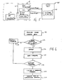
- a procedure for converting portable (processor independent) code, such as JAVA code, into linked target code is shown in Figure 3.
- the procedure uses two functions, a dynamic cross compiler 80 and a dynamic cross linker 82. Each function is implemented on the host processor 12.
- the dynamic cross linker is part of the DSP-API in the preferred embodiment.
- the cross compiler may also be part of the DSP-API.
- the dynamic cross compiler 80 converts portable code into unlinked, executable target processor code.
- the dynamic cross linker 82 converts the unlinked, executable target processor code into linked, executable target processor code. To do so, it must resolve addresses within a block of code, prior to loading on the DSP 16.
- the dynamic cross linker 82 links the code segments and data segments of the function, allocates the memory on the DSP 16, and loads the code and constant data to the DSP 16.
- the functions are referred to as "cross" compiling and "cross” linking, because the functions (compiling and linking) occur on a different processor (i.e., the host processor 12) from the target processor which executes the code (i.e., the DSP 16).
- the dynamic cross compiler 80 accepts previously unlinked code loaded on demand by a user or a user agent (such as a browser). The code is processed to either (1) identify "tagged” sections of the code or (2) analyze untagged code segments for suitability of execution on the DSP 16. A tagged section of source code could delineate source targetable to a DSP by predetermined markers such as " ⁇ start DSP code>" and ⁇ end DSP code>” embedded in the source code. If a tagged section is identified either directly or through analysis, a decision is made to either cross compile or not based on the current processing state of the DSP 16. If a decision is made to compile, the section of code processed by compiling software that outputs unlinked, executable target processor code, using well known compiling methods.
- a decision not to compile could be made if for example, the DSP has insufficient available processing capacity (generally stated as available MIPS - million of instructions per second) or insufficient available memory, due to other tasks being executed by the DSP 16.
- the compiled code can be passed to the dynamic cross linker 82 for immediate use in the DSP 16, or could be saved in the DSP library 58.
- the dynamic cross linker 82 accepts previously unlinked code, which is either (1) statically stored in connection with the host processor 12 or (2) dynamically downloaded to the host processor 12 over a network connection (including global networks such as the Internet) or (3) dynamically generated by the dynamic cross compiler 80.
- the dynamic cross linker 82 links the input code for a memory starting address of the DSP 16 determined at runtime.
- the memory starting address can be determined from a memory map or memory table stored on and managed by either the host processor 12 or DSP 16.
- the dynamic cross linker 82 convert referenced memory locations in the code to actual memory locations in the DSP 16. These memory locations could include, for example, branch addresses in the code or references to locations of data in the code.
- the portable code is in a COFF (common object file format) which contains all information about the code, including whether it is linked or unlinked. If it is unlinked, symbol tables define the address which must be changed for linking the code.
- COFF common object file format
- the dynamic cross compiler 80 allows run-time decisions to be made about where to execute the downloaded portable code. For example, in a system with multiple target processors (such as two DSPs 16), the dynamic cross compiler 80 could compile the portable code to any one of the target processors based on available resources or capabilities.
- the dynamic cross linker 82 provides for linking code to run on a target processor which does not support relocatable code. Since the code is linked at run-time, memory locations in the DSP 16 (or other target processor) do not need to be reserved, allowing optimum efficiency of use of all computing resources in the device. Because the compiling is accomplished with knowledge of the architecture of the platform 10, the compiling can take advantage of processor and platform specific features, such as intelligent cache architectures in one or both processors 12 and 16.
- the DSP 16 can have various functions which are changed dynamically to fully use its processing capabilities.
- the user may wish to 12 load a user interface including voice recognition.
- the host processor 12 could download software and dynamically cross compile and cross link the voice recognition software for execution in the DSP 16.
- previously compiled software in the DSP library 58 could be dynamically cross linked, based on the current status of the DSP 16, for execution.
- the Host Device Driver handles communications from the DSP 16 to the Host Processor 12.
- the driver functions takes the communication requests as specified in the Host-DSP Communications Protocol and handles transmission of the information via the available hardware interface.
- the device driver is RTOS dependent and communications hardware dependent.
- the Host-DSP Communications Protocol governs the communications of commands and data between the Host 12 and the DSP 16.
- the communications consist of several paths: messages, data channels, and streams.
- Messages are used to send initialization parameters and commands to the tasks.
- Data channels carry large amounts of data between tasks and between the DSP 16 and Host 12, in the form of data frames.
- Streams are used to pass streamed data between tasks and between the DSP 16 and Host 12.
- Each task has an entry point to a message handler, which handles messages.
- the messages are user defined and will include initialization parameters for the task's function, and commands for controlling the task.
- the tasks send messages to the Host 12 via the callback specified when the task is created.
- the prototype for the task's message handler and the prototype for the Host's callback are shown here:
- the replyref parameter refers to an implementation dependent reference value, which is used to route the reply back to the sender. For every Send_Message call, the recipient must call Reply_Message using the replyref parameter.
- the actual messages may appear as follows: Sent message MsgPktFlag taskid replyref msgid count buf[7-8] Reply message MsgPktFlag -1 replyref msgid count buf[7-8]
- the multiword data is sent least-significant word first.
- a TaskID of 0 in the Send_Message function indicates a system level message.
- the system level messages are used to implement the DSP-API functions
- Send_Message BOOL Send_Message(T _ TaskID TaskID, T_MsgID MsgID, T_Count count, T_DSP_Word *msgbuf , T_DSP_Word *replybuf , T_Size replybufsize, T_Count replycount, U16 *errcode);
- This function will send a user defined message to a task specified by TaskID.
- the MsgID defines the message, and the msgbufcontains the actual message data.
- the message size is count T_DSP_Words.
- the reply to the message will be contained in the replybuf parameter, which points to a buffer of size replybufsize, provided by the caller. It should be of sufficient size to handle the reply for the particular message.
- the errcode parameter will contain the following possible results: DSP_SUCCESS DSP_DEVID_NOT_FOUND DSP_DEVID_NOT_RESPONDING DSP_TASK_NOT_FOUND Reply_Message BOOL Reply_Message(T_ReplyRef replyref , T _ Count count, T_DSP_Word *buf , U16 *errcode);
- the replyref parameter is a reference used to route the reply back to the sender of the original message, and is implementation specific.
- the reply is contained in the buf parameter and its size is count T_DSP_Words.
- the errcode parameter will contain the following possible results: DSP_SUCCESS DSP_DEVID_NOT_FOUND DSP_DEVID_NOT_RESPONDING DSP_BAD_REPLY_REF
- channels are used to transmit frame-based data from one processor to another, or between tasks on the same processor.
- a channel allocates a specified number and size of frames to contain the data. Initially, the channel will contain a list of empty frames. Tasks that produce data will request empty frames in which to put the data, then once filled, the frame is returned to the channel. Tasks that consume data will request full frames from the channel, and once emptied, the frame is returned to the channel. This requesting and returning of frame buffers allows data to move about with a minimum of copying.
- Each task has a specified Input and Output channel. Once a channel is created, it should be designated as the input to one task, and the output to another task.
- a channel's ID includes a device ID, so channels can pass data between processors.
- Channel data flow across the Host-DSP interface may appear as follows: ChanPktFlag Channel ID Count Data[...] The following are the channel functions: Create_Channel BOOL Create_Channel(T _ DeviceID DevID, T _ Size framesize, T_Count numframes, T_ChanID *ChannelID, U16 *errcode);
- This function creates a data frame-based communication channel.
- This creates a channel control structure which maintains control of a set of frame buffers, whose count and size are specified in the numframes and framesize parameters, respectively.
- the channel allocates the data frames, and adds them to its list of empty frames.
- ChannelID will return the ID of the new channel. If the DevID is not that of the calling processor, a channel control structure is created on both the calling processor and the DevID processor, to control data flowing across the communications interface.
- the errcode parameter will contain the following possible results: CHAN_SUCCESS CHAN_DEVID_NOT_FOUND CHAN_DEVID_NOT_RESPONDING CHAN_ALLOCATION_ERROR Delete_Channel BOOL Delete_Channel(T_ChanID ChannelID, U16 *errcode);
- the errcode parameter will contain the following possible results: CHAN_SUCCESS CHAN_DEVID_NOT_FOUND CHAN_DEVID_NOT RESPONDING CHAN_CHANNEL_NOT_FOUND Request_Empty_Frame BOOL Request_Empty_Frame(T_LocalChanID Chn, T_DSP_Word **bufptr, BOOL WaitFlag, U16 *errcode);
- This function requests an empty frame from the specified local channel ID. If Chn is NULL, then the task's output channel is used. Upon return, the bufptr parameter will contain the pointer to the frame buffer. If the WaitFlag is TRUE, and there is no frame buffer available, the caller will be suspended until a buffer becomes available. If the WaitFlag is FALSE, the function will return regardless.
- the errcode parameter will contain the following possible results: CHAN_SUCCESS CHAN_CHANNEL_NOT_FOUND CHAN_BUFFER_UNAVAILABLE Return_Full_Frame BOOL Return_Full_Frame(T_LocalChanID Chn, T_DSP_Word *bufptr, U16 *errcode);
- a task Once a task has filled a frame buffer, it returns is to the channel using this function. The buffer pointed to by bufptr is returned to the channel ID specified. If Chn is NULL, then the task's output channel is used.
- the errcode parameter will contain the following possible results: CHAN_SUCCESS CHAN_CHANNEL_NOT_FOUND CHAN_BUFFER_CTRL_ERROR Request_Full_Frame BOOL Request_Full_Frame(T_LocalChanID Chn, T_DSP_Word **bufptr , BOOL WaitFlag , U16 *errcode);
- This function requests a full frame of data from the specified local channel ID. If Chn is NULL, then the task's input channel is used. Upon return, the bufptr parameter will contain the pointer to the frame buffer. If the WaitFlag is TRUE, and there are no full frame buffers available, the caller will be suspended until a buffer becomes available. If the WaitFlag is FALSE, the function will return regardless.
- the errcode parameter will contain the following possible results: CHAN_SUCCESS CHAN_CHANNEL_NOT_FOUND CHAN_BUFFER_UNAVAILABLE Return_Empty_Frame BOOL Return_Empty_Frame(T _ LocalChanID Chn, T_DSP_Word *bufptr, U16 *errcode);
- a task Once a task has used the data from a frame buffer, it should return the buffer to the channel using this function.
- the buffer pointed to by bufptr is returned to the channel ID specified. If Chn is NULL, then the task's input channel is used.
- the errcode parameter will contain the following possible results: CHAN_SUCCESS CHAN_CHANNEL_NOT_FOUND CHAN_BUFFER_CTRL_ERROR Set_Task_Input_Channel BOOL Set_Task_Input_Channel(T_Task *TaskID, T_ChanID ChanID, U16 *errcode);
- the errcode parameter will contain the following possible results: CHAN_SUCCESS CHAN_DEVID_NOT_FOUND CHAN_DEVID_NOT_RESPONDING CHAN_TASK_NOT_FOUND CHAN_CHANNEL_NOT_FOUND Set_Task_Output_Channel BOOL Set_Task_Output_Channel(T_Task *TaskID, T_ChanID ChanID, U16 *errcode);
- the errcode parameter will contain the following possible results: CHAN_SUCCESS CHAN_DEVID_NOT_FOUND CHAN_DEVID_NOT_RESPONDING CHAN_TASK_NOT_FOUND CHAN_CHANNEL_NOT_FOUND
- Streams are used for data, which can not be broken into frames, but which continuously flow into and out of a task.
- a stream will consist of a circular buffer (FIFO) with associated head and tail pointers to track the data as it flows in and out.
- Each task can have a designated input and output stream.
- Stream data flow across the Host-DSP interface may appear as follows: StrmPktFlag Stream ID Count Data[...] Following are the stream functions: Create_Stream BOOL Create_Stream(T_DeviceID DevID, T_Size FIFOsize, T_StrmID *StreamID, U16 *errcode);
- This function creates a FIFO-based communication stream.
- This creates a stream control structure which maintains control of a FIFO of size FIFOsize.
- the stream allocates an empty FIFO, and initializes head and tail pointers to handle data flow into and out of the stream.
- StreamID will return the ID of the new stream. If the DevID is not that of the calling processor, a stream control structure is created on both the calling processor and the DevID processor, to control data flowing across the communications interface.
- the errcode parameter will contain the following possible results: STRM_SUCCESS STRM_DEVID_NOT_FOUND STRM_DEVID_NOT_RESPONDING STRM_ALLOCATION_ERROR Delete_Channel BOOL Delete_Stream(T_StrmID StreamID, U16 *errcode);
- the errcode parameter will contain the following possible results: STRM_SUCCESS STRM_DEVID_NOT_FOUND STRM_DEVID_NOT_RESPONDING STRM_STREAM_NOT_FOUND Get_Stream_Count BOOL Get_Stream_Count(T_LocalStrmID StrmID, T _ Count *count, U16 *errcode);
- This function requests the count of T_DSP_Words currently in the stream FIFO specified by StrmID.
- the count parameter will contain the number upon return.
- the errcode parameter will contain the following possible results: STRM_SUCCESS STRM_STREAM_NOT_FOUND Write_Stream BOOL Write_Stream(T_LocalStrmID Strm, T_DSP_Word *bufptr, T _ Count count, T_Count *countwritten, U16 *errcode);
- This function will write count number of T_DSP_Words to the stream specified by the Strm. If Strm is NULL, the task's output stream is used. The data is pointed to by the bufptr parameter. Upon return, countwritten will contain the number of T_DSP_Words actually written.
- the errcode parameter will contain the following possible results: STRM_SUCCESS STRM_DEVID_NOT_FOUND STRM_DEVID_NOT_RESPONDING STRM_STREAM_NOT_FOUND STRM_STREAM_OVERFLOW Read_Stream BOOL Read_Stream(T_LocalStrmID Strm, T_DSP_Word *bufptr, T _ Count maxcount, BOOL WaitFlag, T_Count *countread, U16 *errcode) ;
- This function reads data from the stream specified by Strm. If Strm is NULL, the task's input stream is used. The data will be stored in the buffer pointed to by bufptr. Up to maxcount T_DSP_Words will be read from the stream. The countread parameter will contain the actual count of the data read.
- the errcode parameter will contain the following possible results: STRM_SUCCESS STRM_DEVID_NOT_FOUND STRM_DEVID_NOT_RESPONDING STRM_STREAM_NOT_FOUND Set_Task_Input_Stream BOOL Set_Task_Input_Stream(T_Task *TaskID, T_StrmID StrmID, U16 *errcode);
- the errcode parameter will contain the following possible results: STRM_SUCCESS STRM_DEVID_NOT_FOUND STRM_DEVID_NOT_RESPONDING STRM_TASK_NOT_FOUND STRM_STREAM_NOT_FOUND Set_Task_Output_Stream BOOL Set_Task_Output_Stream(T_Task *TaskID, T_StrmID StrmID, U16 *errcode);
- This function sets a task's output stream to the specified stream ID.
- the errcode parameter will contain the following possible results: STRM_SUCCESS STRM_DEVID_NOT_FOUND STRM_DEVID_NOT_RESPONDING STRM_TASK_NOT_FOUND STRM_STREAM_NOT_FOUND
- T_HostWord A word on the Host processor.
- T_DSP_Word A word on the DSP processor.
- BOOL Boolean value TRUE or FALSE.
- T_DeviceID Processor device ID T_TaskID A structure containing fields for a device ID and a processor local task ID.
- T_ChanID A structure containing fields for a device ID and a processor local channel ID.
- T_DSP_ID An object ID on the DSP.
- T_Size Data type for a size.
- DSP-API Messages Message Send Parameters Reply Parameters Direction Host ⁇ DSP GET_MIPS None U32 mips ⁇ GET_MEM_AVAIL T_Size progmem T_Size datamem ⁇ ALLOC_MEM U16 mempage T_Size size T_DSP_Word *memptr U16 errcode ⁇ FREE_MEM U16 mempage T_DSP_Word *memptr U16 errcode ⁇ PUT_BLOB T_DSP_Ptr destaddr U16 mempage T_Size size T_DSP_Word BLOB[size] U16 errcode ⁇ CREATE_TASK T_TaskCreate tcs T_TaskID TaskID U16 errcode ⁇ START_TASK T_TaskID TaskID U16 errcode ⁇ SUSPEND_TASK T_TaskID TaskID U16
- FIGS 4 - 6 illustrate an embodiment for downloading native code to a target processor (i.e., the host 12 or DSP 16) in a secure and efficient manner.
- This embodiment for downloading code could be used, for example, in downloading code from the Internet, or other global network, from a Local or Wide Area Network, or from a peripheral device, such as a PC Card or Smartcard.
- FIG 4 an embodiment of a JAVA Bean 90 is shown, where the Bean 90 acts as a wrapper for native code 92.
- the Bean further includes several attributes 94, listed as a Code Type attribute 94a, a Code Size attribute 94b and a MIPS Required attribute 94c.
- the Bean 90 has several actions 96, including a Load Code action 96a, a Load Parameters action 96b and an Execute Parameter 96c.
- the Load Code action 96a is used to load external native code (native to the target processor) into the Bean. Since JAVA Beans have persistence, the Bean 90 can store its internal state, including the native code 92 and the attributes 94.
- the Load Parameters action 96b retrieves parameters from the native code 92 (using, for example, the COFF file format described above) and stores the parameters as attributes 94a-c.
- the Execute action 96c executes tasks installed in the DSP 16.
- Figure 5 illustrates use of the Bean 90 to download code to the target processor.
- the target processor is the DSP 16 (or one of multiple DSPs 16), although it could be used to download native code to the host processor 12 as well.
- the desired Bean 90 is resident in a network server, such as a LAN server or an Internet server, although the Bean could be resident in any device in communication with the platform 10, such as a Smartcard.
- the connection to the network server 100 will often be wireless.
- the platform 10 is coupled to a network server 100.
- the host processor 12, as shown in greater detail in Figure 2, may execute one or more JAVA applets 41 through a JAVA virtual machine 45.
- the host 12 loads an applet 41 containing the Bean 90 from the network server 100 or the Bean, without the containing applet, can be downloaded from the server 100.
- the wrapper Bean 90 Once the wrapper Bean 90 has been retrieved, it can be queried for the size of the native code, code type (for which processor is the code intended) and MIPs required. If the intended processor has sufficient resources to run the code 92, the code 92 can be installed to execute on the intended processor, either the host processor 12 or DSP 16 in the architecture shown in Figure 5.
- the native code 92 will be unlinked, compiled code.
- the cross linker 82 of the DSP-API 50 will link the code to an available memory location.
- the Bean would pass the binary native code 92 to the dynamic cross linker 82, which would install and execute the code.
- a typical manner in which a download of native code might occur is when the user is running an applet 41 in which a DSP function is desired.
- the applet 41 would check to see if the desired code was installed as a task 60 in the DSP or was available in the DSP Library 58. If so, the task could be executed without a download.
- an object (referred to as the " DSPLoader" object herein) could be created to load the Bean 90.
- DSPLoader class is local on the host 12, JAVA will check to see if the Bean is available locally as well. In a first instance, there may be a Bean with the code stored locally. If so, the code from the Bean is installed to the DSP 16 (or to whichever processor specified by the Code Type). If a Bean without the code is stored locally, the Bean can retrieve the code from the appropriate server.
- JAVA will load the Bean 90 from the server that wrote the applet 41.
- the code from the Bean will then be installed as described above.
- JAVA Bean or other applet as a wrapper to the native code has significant advantages.
- a JAVA Bean or ActiveX applet may be signed by the source of the code; when the Bean or applet is downloaded, the signature is verified by the receiving application, which has a list of trusted sources. If the Bean or applet is signed by a trusted source, it can be decrypted using standard techniques. Accordingly, the native code is encrypted during transmission along with the code of the Bean or applet, preventing unauthorized modification of the code. Because the native code is secure and comes from a trusted source, the attributes can also be trusted as accurate.
- Figure 6 illustrates a flow chart describing the process of downloading native code for a processor using a JAVA Bean, it being understood that the native code could be wrapped in an applet of a different language using similar techniques.
- the encrypted, digitally signed Bean 90 is downloaded to a device running a JAVA virtual machine.
- the signature is verified. If it is not from a source listed as a trusted source, exception processing is enabled in step 114. In the case of the Bean coming from a trusted source, the exception processing function may give the user an opportunity to accept the Bean, if the user is comfortable with the source. If the signature is invalid, the exception processing may delete the Bean 90 and send an appropriate error message to the user.
- step 116 the Bean is decrypted in step 116. This step decrypts both the JAVA code and the native code in the Bean.
- step 118 the attributes are retrieved from the Bean 90 and in step 120 the applet determines whether the appropriate processor has sufficient resources to run the code. If not, the exception processing step 114 may decline to install the native code, or steps may be taken to free resources. If there are sufficient resources, the code is linked using the cross-linker and installed on the desired processor in step 122. In step 124, the native code is executed.
- the NativeBean() routine creates the Bean 90 which will hold the native code.
- the loadCode() routine gets the native code from the server.
- the getFunctionName() and getCodeBase() routines retrieve attributes.
- the installCode() routine calls the cross linker to link the native code to the DSP and to load the linked code.
- the loadParameters() routine instructs the Bean to examine the native code and determine its attributes.
- the getCodesize() and getCodetype() routines transfer the attributes to the requesting applet.
Abstract
Description
- This invention relates in general to mobile electronic devices and, more particularly, to a hardware and software platform for mobile electronic devices.
- Handheld portable devices are gaining popularity as the power and, hence, functionality of the devices increases. Personal Digital Assistants (PDAs) are currently in widespread use and Smartphones, which combine some of the capabilities of a cellular phone and a PDA, are expected to have a significant impact on communications in the near future.
- Some devices currently incorporate one or more DSPs (digital signal processor) or other coprocessors for providing certain discrete features, such as voice recognition, and a general purpose processor for other data processing functions. The code for the DSP and the code for the general purpose processor is generally stored in ROMs or other nonvolatile memories, which are not easily modified. Thus, as improvements and new features become available, it is often not possible to upgrade the capabilities of the device. In particular, it is not possible to maximize the use of the DSPs or other coprocessor which may be present in the device.
- Therefore, a need exists for a data processing architecture which can be upgraded and optimizes use of multiple processors and coprocessors.
- The teachings of the present application disclose a mobile electronic device that comprises a coprocessor for executing native code, a host processor system operable to execute native code corresponding to the host processor system and processor independent code. The host processor system is operable to dynamically change the tasks performed by the digital signal coprocessor. Communication circuitry provides for communication between the host processor system and the coprocessor.
- This mobile electronic device significant advantages over the prior art. Because the host processor system can dynamically allocate the tasks being performed by the coprocessor, which may be a digital signal processor, to fully use the coprocessor. The host processor system may direct a routine to one of a plurality of coprocessors, depending upon a variety of factors, such the present capabilities of each processor.
- For a more complete understanding of the present invention, and the advantages thereof, reference is now made to the following descriptions taken in conjunction with the accompanying drawings, in which:
- Figure 1 illustrates a block diagram of a platform architecture particularly suited for general wireless data processing;
- Figure 2 illustrates a functional block diagram of the platform of Figure 1;
- Figure 3 illustrates a functional block diagram of dynamic cross compiling and dynamic cross linking functions;
- Figure 4 illustrate an embodiment of native code for execution on a processor being encapsulated in a JAVA Bean wrapper for downloading to a device;
- Figure 5 illustrates the operation of transferring the encapsulated native code to a processor on a device from a JAVA Bean located on a remote server; and
- Figure 6 illustrates a flow diagram describing security features associated with the operation of Figure 5.
-
- Figure 1 illustrates a preferred embodiment of a general wireless data platform architecture, which could be used for example, in the implementation of a Smartphone or PDA. The
wireless data platform 10 includes a general purpose (Host)processor 12 coupled to bus structure 14, includingdata bus 14a, address bus 14b and control bus 14c. One or more DSPs (or other coprocessors) 16, including the core processor 16a and the peripheral interface 16b, are coupled to bus 14 and to memory andtraffic controller 18, which includes aDSP cache memory 18a, a CPU cache 18b, and a MMU (memory management unit) 18c. Hardware accelerator circuit 20 (for accelerating a portable language such as JAVA) and a video and LCD controller 22 are also coupled to the memory andtraffic controller 18. The output of the video and LCD controller is coupled to an LCD or video display 24. - Memory &
traffic controller 18 is coupled to bus 14 and to themain memory 26, shown as an SDRAM (synchronous dynamic random access memory). Bus 14 is also connected to I/O controller 28,interface 30, and RAM/ROM 32. A plurality of devices could be coupled to thewireless data platform 10, such assmartcard 34, keyboard 36,mouse 38, or one or moreserial ports 40, such as a USB (universal serial bus) port or an RS232 serial port.Interface 30 can couple to aflash memory card 42 and/or a DRAM card 44. The peripheral interface 16b can couple theDSP 16 to a DAC (digital to analog converter) 46, anetwork interface 48 or to other devices. - The
wireless data platform 10 of Figure 1 utilizes both ageneral purpose processor 12 and a DSP 16. Unlike current devices in which the DSP 16 is dedicated to specific fixed functions, the DSP 16 of Figure 1 can be used for any number of functions. This allows the user to derive the full benefit of the DSP 16. - One main area in which the DSP 16 can be used is in connection with the man-machine interface (MMI). Importantly, functions like speech recognition, image and video compression and decompression, data encryption, text-to-speech conversion, and so on, can be performed much more efficiently using the
DSP 16. The proposed architecture allows new functions and enhancements to be easily added towireless data platform 10. - It should be noted that the
wireless data platform 10 is a general block diagram and many modifications could be made. For example, Figure 1 illustrates separate DSP andprocessor caches 18a and 18b. As would be known to one skilled in the art, a unified cache could also be used. Further, thehardware acceleration circuit 20 is an optional item. Such devices speed the execution of languages such as JAVA; however, the circuit is not necessary for operation of the device. Further, although the illustrated embodiment shows a single DSP, multiple DSPs (or other coprocessors) could be coupled to the buses. - Figure 2 illustrates a functional software architecture for the
wireless data platform 10. This block diagram presumes the use of JAVA; it should be noted that languages other than JAVA could be used as well. Functionally, the software is divided into two groups, Host processor software and DSP software. The Host software includes one ormore applets 41 . The DSPAPI class 43 is a JAVA API package for JAVA applications or applets to access the functionality of the DSPAPI 50 and HostDSP Interface Layer 52. A JAVA virtual machine (VM) 45 interprets the applets. The JAVA native interface 47 is the method which the JAVA VM executes host processor or platform specific code.Native tasks 49 are non-JAVA programs which can be executed by theHost processor 12 without using the JAVA native interface. The DSPAPI 50, described in greater detail hereinbelow, is an API (application program interface) used theHost 12 to call to make use of the capabilities of theDSP 16. The Host-DSP Interface Layer 52 provides an API for theHost 12 and DSP 16 to communicate with each other, with other tasks, or other hardware using channels via the Host-DSP Communication Protocol. TheDSP device driver 54 is the Host based device driver for the Host RTOS 56 (real time operating system) to communicate with theDSP 16. The Host RTOS 56 is an operating system, such as NUCLEUS PLUS by Accelerated Technology Incorporated. - Alternatively a non-real time operating system, such as WINDOWS CE by Microsoft Corporation, could be used. The DSP Library 58 contains programs stored for execution on the DSP 16.
- On the DSP side, one or
more tasks 60 can be stored in memory for execution by the DSP16. As described below, the tasks can be moved in and out of the memory as desired, such that the functionality of the DSP is dynamic, rather than static. The Host-DSP Interface layer 62 on the DSP side performs the same function as the Host-DSP Interface layer 52 on the Host side, namely it allows theHost 12 and DSP 16 to communicate. The DSP RTOS 64 is the operating system for the DSP processor. The Host Device driver 66 is a DSP based device driver for the DSP RTOS 64 to communicate with theHost 12. The Host-DSP Interface 70 couples theDSP 16 andHost 12. - In operation, the software architecture shown in Figure 2 uses the
DSP 16 as a variable function device, rather than a fixed function device as in the prior art. - Accordingly, the DSP functions can be downloaded to the mobile device incorporating the architecture of Figure 2 to allow the
DSP 16 to perform various signal processing functions for theHost 12. - The DSP-API provides a device independent interface from the
Host 12 to theDSP 16. The functions provide theHost 12 with the ability to load and schedule tasks on theDSP 16 and to control and communicate with those tasks. The API functions include calls to: determine the DSP's available resources, create and controlHost 12 and DSP tasks, create and control data channels betweenHost 12 and DSP tasks, and communicate with tasks. These functions are described below. Each function returns a BOOLean result, which will be SUCCESS for a successful operation, or FAILURE. If the result is FAILURE, the errcode should be checked to determine which error occurred.
DSP_Get_MIPS
BOOL DSP_Get_MIPS(T_DeviceID DevID, U32 *mips, U16 *errcode); - This function returns the current MIPS available on the DSP. This consists of the MIPS capability of the
DSP 16 minus a base MIPS value (the MIPS value with no additional dynamic tasks, i.e. the kernel plus API code plus drivers), minus the sum of the MIPS ratings for all loaded dynamic tasks. The errcode parameter will contain the following possible results:
DSP_SUCCESS
DSP_DEVID_NOT_FOUND
DSP_DEVID_NOT_RESPONDING
DSP_Get_Memory_Available
BOOL DSP_Get_Memory_Available(T_DeviceID DevID, T_Size *progmem, T_Size *datamem, U16 *errcode); - This function will query the
DSP 16 specified by DevID for the amounts of available memory for both program memory and data memory. The resultant values are returned in the progmem and datamem parameters. The sizes are specified in T_DSP_Words. The errcode parameter will contain the following possible results:
DSP_SUCCESS
DSP_DEVID_NOT_FOUND
DSP_DEVID_NOT_RESPONDING
DSP_Alloc_Mem
BOOL DSP_Alloc_Mem(T_DeviceID DevID, U16 mempage, T_Size size, T_DSP_Word **memptr, U16 *errcode); - This function will allocate a block of memory on a
DSP 16. The DevID specifies which device on which to allocate the memory. The mempage is 0 for program space, and 1 for data space. The size parameter specifies the memory block size in T_DSP_Words. The returned memptr will be a pointer to the memory block on theDSP 16, or NULL on failure. The errcode parameter will contain the following possible results:
DSP_SUCCESS
DSP_DEVID_NOT_FOUND
DSP_DEVID_NOT_RESPONDING
DSP_INVALID_MEMPAGE
DSP_NOT_ENOUGH_MEMORY
DSP_Free_Mem
BOOL DSP_Free_Mem(T_DeviceID DevID, U16 mempage, T_DSP_Word *memptr, U16 *errcode); - This function will free a block of memory on a DSP that was allocated with the DSP_Alloc_Mem function. The DevID specifies on which device the memory resides. The mempage is 0 for program space, and 1 for data space. The memptr parameter is the pointer to the memory block. The errcode parameter will contain the following possible results:
DSP_SUCCESS
DSP_DEVID_NOT_FOUND
DSP_DEVID_NOT_RESPONDING
DSP_INVALID_MEMPAGE
DSP_MEMBLOCK_NOT_FOUND
DSP_Get_Code_Info
BOOL DSP_Get_Code_Info(char *Name, T_CodeHdr *codehdr, U16 *errcode); - This function will access the DSP Library table and return the code header for the DSP function code specified by the Name parameter. On return, the location pointed to by the codehdr parameter will contain the code header information. The errcode parameter will contain the following possible results:
DSP_SUCCESS
DSP_NAMED_FUNC_NOT_FOUND
DSP_Link_Code
BOOL DSP_Link_Code(T_DeviceID DevID, T_CodeHdr *codehdr, T_TaskCreate *tcs, U16 *errcode); - This function will link DSP function code so that it will run at a specified address on the DSP specified by DevID. The codehdr parameter points to the code header for the function. The dynamic cross linker will link the code based on information in the code header, and in the code (COFF file). The dynamic cross linker will allocate the memory as needed, and link and load the code to the
DSP 16. The tcs parameter is a pointer to the task creation structure needed in the DSP_Create_Task function. DSP_Link_Code will fill in the code entry points, priority, and quantum fields of the structure in preparation for creating a task. The errcode parameter will contain the following possible results:
DSP_SUCCESS
DSP_DEVID_NOT_FOUND
DSP_DEVID_NOT_RESPONDING
DSP_NOT_ENOUGH_PROG_MEMORY
DSP_NOT_ENOUGH_DATA_MEMORY
DSP_COULD_NOT_LOAD_CODE
DSP_Put_BLOB
BOOL DSP_Put_BLOB(T_DeviceID DevID, T_HostPtr srcaddr, T_DSP_Ptr destaddr, U16 mempage, T_Size size, U16 *errcode); - This function will copy a specified Binary Large Object (BLOB) to the
DSP 16. The DevID specifies on whichDSP 16 to copy the object. The srcaddr parameter is a pointer to the object in Host memory. The destaddr is a pointer to the location to which to copy the object on theDSP 16. The mempage is 0 for program space, and 1 for data space. The size parameter specifies the size of the object in T_DSP_Words. The errcode parameter will contain the following possible results :
DSP_SUCCESS
DSP_DEVID_NOT_FOUND
DSP_DEVID_NOT_RESPONDING
DSP_INVALID_MEMPAGE
DSP_Create_Task
BOOL DSP_Create_Task(T_DeviceID DevID, T_TaskCreate *tcs, T_TaskID *TaskID, U16 *errcode); - DSP_Create_Task requests the
DSP 16 to create a task given the task parameters and the code locations in the DSP's program space. The Task Creation Structure is show in Table 1:Task Creation Structure. Data Type Field Name Description T_DSP_Name Name User defined name for the task. U32 MIPS MIPS used by the task. T_ChanID ChanIn The channel ID used for task input. T_ChanID ChanOut The channel ID used for task output T_StrmID StrmIn The stream ID used for task input T_StrmID StrmOut The stream ID used for task output. U16 Priority The task's priority. U32 Quantum The task's timeslice in system ticks. T_Size StackReq The amount of stack required. T_DSP_Ptr MsgHandler Pointer to code to handle messages to the task. T_HOST_Ptr CallBack Pointer to Host code to handle messages from the task. T_DSP_Ptr Create Pointer to code to execute when task is created. T_DSP_Ptr Start Pointer to code to execute when task is started. T_DSP_Ptr Suspend Pointer to code to execute when task is suspended. T_DSP_Ptr Resume Pointer to code to execute when task is resumed. T_DSP_Ptr Stop Pointer to code to execute when task is stopped. - Once the task is created, the Create entry point will be called, giving the task the opportunity to do any necessary preliminary initialization. The Create, Suspend, Resume, and Stop entry points can be NULL. The resultant TaskID contains both the device ID (DevID), and the DSP's task ID. If the TaskID is NULL, the create failed. The errcode parameter will contain the following possible results:
DSP_SUCCESS
DSP_DEVID_NOT_FOUND
DSP_DEVID_NOT_RESPONDING
DSP_INVALID_PRIORITY
DSP_CHANNEL_NOT_FOUND
DSP_ALLOCATION_ERROR
DSP_Start_Task
BOOL DSP_Start_Task(T_TaskID TaskID, U16 *errcode); - This function will start a DSP task specified by TaskID. Execution will begin at the task's Start entry point. The errcode parameter will contain the following possible results:
DSP_SUCCESS
DSP_DEVID_NOT_FOUND
DSP_DEVID_NOT_RESPONDING
DSP_TASK_NOT_FOUND
DSP_Suspend_Task
BOOL DSP_Suspend_Task(T_TaskID TaskID, U16 *errcode); - This function will suspend a DSP task specified by TaskID. Prior to being suspended, the task's Suspend entry point will be called to give the task a chance to perform any necessary housekeeping. The errcode parameter will contain the following possible results:
DSP_SUCCESS
DSP_DEVID_NOT_FOUND
DSP_DEVID_NOT_RESPONDING
DSP_TASK_NOT_FOUND
DSP_Resume_Task
BOOL DSP_Resume_Task(T_TaskID TaskID, U16 *errcode); - This function will resume a DSP task that was suspended by DSP_Suspend_Task. Prior to being resumed, the task's Resume entry point will be called to give the task a chance to perform any necessary housekeeping. The errcode parameter will contain the following possible results:
DSP_SUCCESS
DSP_DEVID_NOT_FOUND
DSP_DEVID_NOT_RESPONDING
DSP_TASK_NOT_FOUND
DSP_TASK_NOT_SUSPENDED
DSP_Delete_Task
BOOL DSP_Delete_Task(T_TaskID TaskID, U16 *errcode); - This function will delete a DSP task specified by TaskID. Prior to the deletion, the task's Stop entry point will be called to give the task a chance to perform any necessary cleanup. This should include freeing any memory that was allocated by the task, and returning any resources the task acquired. The errcode parameter will contain the following possible results:
DSP_SUCCESS
DSP_DEVID_NOT_FOUND
DSP_DEVID_NOT_RESPONDING
DSP_TASK_NOT_FOUND
DSP_Change_Task_Priority
BOOL DSP_Change_Task_Priority(T_TaskID TaskID, U16 newpriority, U16 *oldpriority, U16 *errcode); - This function will change the priority of a DSP task specified by TaskID. The priority will be changed to newpriority. The possible values of newpriority are RTOS dependent. Upon return, the oldpriority parameter will be set to the previous priority of the task. The errcode parameter will contain the following possible results:
DSP_SUCCESS
DSP_DEVID_NOT_FOUND
DSP_DEVID_NOT_RESPONDING
DSP_TASK_NOT_FOUND
DSP_INVALID_PRIORITY
DSP_Get_Task_Status
BOOL DSP_Get_Task_Status(T_TaskID TaskID, U16 *status, U16 *priority, T_ChanID *Input, T_ChanID *Output, U16 *errcode); - This function returns the status for a DSP task specified by TaskID. The status will be one of the following values:
DSP_TASK_RUNNING
DSP_TASK_SUSPENDED
DSP_TASK_WAITFOR_SEM
DSP_TASK_WAITFOR_QUEUE
DSP_TASK_WAITFOR_MSG - The priority parameter will contain the task's priority, and the Input and Output parameters will contain the task's input and output channel IDs, respectively. The errcode parameter will contain the following possible results:
DSP_SUCCESS
DSP_DEVID_NOT_FOUND
DSP_DEVID_NOT_RESPONDING
DSP_TASK_NOT_FOUND
DSP_Get_ID_From_Name
BOOL DSP_Get_ID_From_Name(T_DeviceID DevID, T_DSP_Name Name, T_DSP_ID *ID, U16 *errcode); - This function returns the ID for a named object on the
DSP 16. The named object may be a channel, a task, a memory block, or any other supported named DSP object. The errcode parameter will contain the following possible results:
DSP_SUCCESS
DSP_DEVID_NOT_FOUND
DSP_DEVID_NOT_RESPONDING
DSP_NAME_NOT_FOUND
DSP_Dbg_Read_Mem
BOOL DSP_Dbg_Read_Mem(DEVICE_ID DevID, U8 mempage, DSP_PTR addr, U32 count, DSP_WORD *buf, U16 *errcode); - This function requests a block of memory. The mempage specifies program memory (0) or data memory (1). The addr parameter specifies the memory starting address, and the count indicates how many T_DSP_Words to read. The bufparameter is a pointer to a caller provided buffer to which the memory should be copied. The errcode parameter will contain the following possible results:
DSP_SUCCESS
DSP_DEVID_NOT_FOUND
DSP_DEVID_NOT_RESPONDING
DSP_INVALID_MEMPAGE
DSP_Dbg_Write_Mem
BOOL DSP_Dbg_Write_Mem(T_DeviceID DevID, U16 mempage, T DSP_Ptr addr, T_Count count, T_DSP_Word *buf, U16 *errcode); - This function writes a block of memory. The mempage specifies program memory (0) or data memory (1). The addr parameter specifies the memory starting address, and the count indicates how many T_DSP_Words to write. The buf parameter is a pointer the buffer containing the memory to write. The errcode parameter will contain the following possible results:
DSP_SUCCESS
DSP_DEVID_NOT_FOUND
DSP_DEVID_NOT_RESPONDING
DSP_INVALID_MEMPAGE
DSP_Dbg_Read_Reg
BOOL DSP_Dbg_Read_Reg(T_DeviceID DevID, U16 RegID, T_DSP_Word *regvalue, U16 *errcode); - This function reads a DSP register and returns the value in regvalue. The RegID parameter specifies which register to return. If the RegID is -1, then all of the register values are returned. The regvalue parameter, which is a pointer to a caller provided buffer, should point to sufficient storage to hold all of the values. The register IDs are DSP specific and will depend on a particular implementation. The errcode parameter will contain the following possible results:
DSP_SUCCESS
DSP_DEVID_NOT_FOUND
DSP_DEVID_NOT_RESPONDING
DSP_INVALID_REGISTER
DSP_Dbg_Write_Reg
BOOL DSP_Dbg_Write_Reg(T_DeviceID DevID, U16 RegID, T_DSP_Word regvalue, U16 *errcode); - This function writes a DSP register. The RegID parameter specifies which register to modify. regvalue contains the new value to write. The register IDs are DSP specific and will depend on a particular implementation. The errcode parameter will contain the following possible results:
DSP_SUCCESS
DSP_DEVID_NOT_FOUND
DSP_DEVID_NOT_RESPONDING
DSP_INVALID_REGISTER
DSP_Dbg_Set_Break
BOOL DSP_Dbg_Set_Break(T_DeviceID DevID, DSP_Ptr addr, U16 *errcode); This function sets a break point at the given code address (addr). The errcode parameter will contain the following possible results:
DSP_SUCCESS
DSP_DEVID_NOT_FOUND
DSP_DEVID_NOT_RESPONDING
DSP_Dbg_Clr_Break
BOOL DSP_Dbg_Clr_Break(T_DeviceID DevID, T_DSP_Ptr addr, U16 *errcode); - This function clears a break point that was previously set by DSP_Dbg_Set_Break at the given code address (addr). The errcode parameter will contain the following possible results:
DSP_SUCCESS
DSP_DEVID_NOT_FOUND
DSP_DEVID_NOT_RESPONDING
DSP_BP_DID_NOT_EXIST - The
DSP Device Driver 54 handles communications from theHost 12 to theDSP 16. The driver functions will take the communication requests as specified in the Host-DSP Communications Protocol and handle the transmission of the information via the available hardware interface. The device driver is RTOS dependent and communications hardware dependent. - The DSP Library 58 contains the blocks of code that can be downloaded to the
DSP 16 for execution. Each block of code will be previously unlinked, or relocatably linked as a library, so that the dynamic cross linker can resolve all address references. Each code block will also include information about the block's requirements for DSP MIPS (millions of instructions per second), priority, time slice quantum, and memory. The format for the code block header is shown in Table 2. The program memory and data memory sizes are approximations to give the Host 12 a quick check on whether the DSP can support the task's memory requirements. If there appears to be sufficient space, the dynamic cross linker can then attempt to link and load the code. It should be noted that the dynamic cross linker could still fail, due to page alignment and contiguity requirements. In the preferred embodiment, the code is in a version 2 COFF file format.Code Block Header. Data Type Field Name Description U16 Processor The target processor type. T_DSP_Name Name Task's name. U32 MIPS Worst case MIPS required by the task. T_Size ProgSize Total program memory size needed. T_Size DataSize Total data memory size needed. T_Size InFrameSize Size of a frame in the task's input channel. T_Size OutFrameSize Size of a frame in the task's output channel. T_Size InStrmSize Size of the task's input stream FIFO. T_Size OutStrmSize Size of the task's output stream FIFO. U16 Priority Task's priority. U32 Quantum Task's time slice quantum (number of system ticks). T_Size StackReq Stack required. T_Size CoffSize Total size of the COFF file. T_DSP_Ptr MsgHandler Offset to a message handler entry point for the task. T_DSP_Ptr Create Offset to a create entry point that is called when the task is created. T_DSP_Ptr Start Offset to the start of the task's code. T_DSP_Ptr Suspend Offset to a suspend entry point that is called prior to the task being suspended. T_DSP_Ptr Resume Offset to a resume entry point that is called prior to the task being resumed. T_DSP_Ptr Stop Offset to a stop entry point that is called prior to the task being deleted. T_Host_Ptr CoffPtr Pointer to the location of the COFF data in the DSP Library. - A procedure for converting portable (processor independent) code, such as JAVA code, into linked target code is shown in Figure 3. The procedure uses two functions, a
dynamic cross compiler 80 and a dynamic cross linker 82. Each function is implemented on thehost processor 12. The dynamic cross linker is part of the DSP-API in the preferred embodiment. The cross compiler may also be part of the DSP-API. - The
dynamic cross compiler 80 converts portable code into unlinked, executable target processor code. The dynamic cross linker 82 converts the unlinked, executable target processor code into linked, executable target processor code. To do so, it must resolve addresses within a block of code, prior to loading on theDSP 16. The dynamic cross linker 82 links the code segments and data segments of the function, allocates the memory on theDSP 16, and loads the code and constant data to theDSP 16. The functions are referred to as "cross" compiling and "cross" linking, because the functions (compiling and linking) occur on a different processor (i.e., the host processor 12) from the target processor which executes the code (i.e., the DSP 16). - The
dynamic cross compiler 80 accepts previously unlinked code loaded on demand by a user or a user agent (such as a browser). The code is processed to either (1) identify "tagged" sections of the code or (2) analyze untagged code segments for suitability of execution on theDSP 16. A tagged section of source code could delineate source targetable to a DSP by predetermined markers such as "<start DSP code>" and <end DSP code>" embedded in the source code. If a tagged section is identified either directly or through analysis, a decision is made to either cross compile or not based on the current processing state of theDSP 16. If a decision is made to compile, the section of code processed by compiling software that outputs unlinked, executable target processor code, using well known compiling methods. A decision not to compile could be made if for example, the DSP has insufficient available processing capacity (generally stated as available MIPS - million of instructions per second) or insufficient available memory, due to other tasks being executed by theDSP 16. The compiled code can be passed to the dynamic cross linker 82 for immediate use in theDSP 16, or could be saved in the DSP library 58. - The dynamic cross linker 82 accepts previously unlinked code, which is either (1) statically stored in connection with the
host processor 12 or (2) dynamically downloaded to thehost processor 12 over a network connection (including global networks such as the Internet) or (3) dynamically generated by thedynamic cross compiler 80. The dynamic cross linker 82 links the input code for a memory starting address of theDSP 16 determined at runtime. The memory starting address can be determined from a memory map or memory table stored on and managed by either thehost processor 12 orDSP 16. The dynamic cross linker 82 convert referenced memory locations in the code to actual memory locations in theDSP 16. These memory locations could include, for example, branch addresses in the code or references to locations of data in the code. - In the preferred embodiment, the portable code is in a COFF (common object file format) which contains all information about the code, including whether it is linked or unlinked. If it is unlinked, symbol tables define the address which must be changed for linking the code.
- The conversion process described above has several significant advantages over the prior art. First, the
dynamic cross compiler 80 allows run-time decisions to be made about where to execute the downloaded portable code. For example, in a system with multiple target processors (such as two DSPs 16), thedynamic cross compiler 80 could compile the portable code to any one of the target processors based on available resources or capabilities. The dynamic cross linker 82 provides for linking code to run on a target processor which does not support relocatable code. Since the code is linked at run-time, memory locations in the DSP 16 (or other target processor) do not need to be reserved, allowing optimum efficiency of use of all computing resources in the device. Because the compiling is accomplished with knowledge of the architecture of theplatform 10, the compiling can take advantage of processor and platform specific features, such as intelligent cache architectures in one or bothprocessors - Thus, the
DSP 16 can have various functions which are changed dynamically to fully use its processing capabilities. For example, the user may wish to 12 load a user interface including voice recognition. At that time, thehost processor 12 could download software and dynamically cross compile and cross link the voice recognition software for execution in theDSP 16. Alternatively, previously compiled software in the DSP library 58 could be dynamically cross linked, based on the current status of theDSP 16, for execution. - The Host Device Driver handles communications from the
DSP 16 to theHost Processor 12. The driver functions takes the communication requests as specified in the Host-DSP Communications Protocol and handles transmission of the information via the available hardware interface. The device driver is RTOS dependent and communications hardware dependent. - The Host-DSP Communications Protocol governs the communications of commands and data between the
Host 12 and theDSP 16. The communications consist of several paths: messages, data channels, and streams. Messages are used to send initialization parameters and commands to the tasks. Data channels carry large amounts of data between tasks and between theDSP 16 andHost 12, in the form of data frames. Streams are used to pass streamed data between tasks and between theDSP 16 andHost 12. - Each task has an entry point to a message handler, which handles messages. The messages are user defined and will include initialization parameters for the task's function, and commands for controlling the task. The tasks send messages to the
Host 12 via the callback specified when the task is created. The prototype for the task's message handler and the prototype for the Host's callback are shown here: - void TaskMsgHandler(T_ReplyRef replyref, T_MsgID MsgID, T_Count count, T_DSP_Word *buf);
- void HostCallBack(T_ReplyRef replyref T_MsgID MsgID, T_Count count, T_DSP_Word *buf);
-
- The replyref parameter refers to an implementation dependent reference value, which is used to route the reply back to the sender. For every Send_Message call, the recipient must call Reply_Message using the replyref parameter. The actual messages may appear as follows:
Sent message MsgPktFlag taskid replyref msgid count buf[.....] Reply message MsgPktFlag -1 replyref msgid count buf[.....] - A TaskID of 0 in the Send_Message function indicates a system level message. The system level messages are used to implement the DSP-API functions
- Following are the Message functions:
Send_Message
BOOL Send_Message(T_TaskID TaskID, T_MsgID MsgID, T_Count count, T_DSP_Word *msgbuf, T_DSP_Word *replybuf, T_Size replybufsize, T_Count replycount, U16 *errcode); - This function will send a user defined message to a task specified by TaskID. The MsgID defines the message, and the msgbufcontains the actual message data. The message size is count T_DSP_Words. The reply to the message will be contained in the replybuf parameter, which points to a buffer of size replybufsize, provided by the caller. It should be of sufficient size to handle the reply for the particular message. The errcode parameter will contain the following possible results:
DSP_SUCCESS
DSP_DEVID_NOT_FOUND
DSP_DEVID_NOT_RESPONDING
DSP_TASK_NOT_FOUND
Reply_Message
BOOL Reply_Message(T_ReplyRef replyref, T_Count count, T_DSP_Word *buf, U16 *errcode); - This function is used to reply to messages. The replyref parameter is a reference used to route the reply back to the sender of the original message, and is implementation specific. The reply is contained in the buf parameter and its size is count T_DSP_Words. The errcode parameter will contain the following possible results:
DSP_SUCCESS
DSP_DEVID_NOT_FOUND
DSP_DEVID_NOT_RESPONDING
DSP_BAD_REPLY_REF - The concept of channels is used to transmit frame-based data from one processor to another, or between tasks on the same processor. When created, a channel allocates a specified number and size of frames to contain the data. Initially, the channel will contain a list of empty frames. Tasks that produce data will request empty frames in which to put the data, then once filled, the frame is returned to the channel. Tasks that consume data will request full frames from the channel, and once emptied, the frame is returned to the channel. This requesting and returning of frame buffers allows data to move about with a minimum of copying.
- Each task has a specified Input and Output channel. Once a channel is created, it should be designated as the input to one task, and the output to another task. A channel's ID includes a device ID, so channels can pass data between processors. Channel data flow across the Host-DSP interface may appear as follows:
ChanPktFlag Channel ID Count Data[...]
Create_Channel
BOOL Create_Channel(T_DeviceID DevID, T_Size framesize, T_Count numframes, T_ChanID *ChannelID, U16 *errcode); - This function creates a data frame-based communication channel. This creates a channel control structure, which maintains control of a set of frame buffers, whose count and size are specified in the numframes and framesize parameters, respectively. When created, the channel allocates the data frames, and adds them to its list of empty frames. ChannelID will return the ID of the new channel. If the DevID is not that of the calling processor, a channel control structure is created on both the calling processor and the DevID processor, to control data flowing across the communications interface. The errcode parameter will contain the following possible results:
CHAN_SUCCESS
CHAN_DEVID_NOT_FOUND
CHAN_DEVID_NOT_RESPONDING
CHAN_ALLOCATION_ERROR
Delete_Channel
BOOL Delete_Channel(T_ChanID ChannelID, U16 *errcode); - This function deletes an existing channel specified by ChannelID. The errcode parameter will contain the following possible results:
CHAN_SUCCESS
CHAN_DEVID_NOT_FOUND
CHAN_DEVID_NOT RESPONDING
CHAN_CHANNEL_NOT_FOUND
Request_Empty_Frame
BOOL Request_Empty_Frame(T_LocalChanID Chn, T_DSP_Word **bufptr, BOOL WaitFlag, U16 *errcode); - This function requests an empty frame from the specified local channel ID. If Chn is NULL, then the task's output channel is used. Upon return, the bufptr parameter will contain the pointer to the frame buffer. If the WaitFlag is TRUE, and there is no frame buffer available, the caller will be suspended until a buffer becomes available. If the WaitFlag is FALSE, the function will return regardless. The errcode parameter will contain the following possible results:
CHAN_SUCCESS
CHAN_CHANNEL_NOT_FOUND
CHAN_BUFFER_UNAVAILABLE
Return_Full_Frame
BOOL Return_Full_Frame(T_LocalChanID Chn, T_DSP_Word *bufptr, U16 *errcode); - Once a task has filled a frame buffer, it returns is to the channel using this function. The buffer pointed to by bufptr is returned to the channel ID specified. If Chn is NULL, then the task's output channel is used. The errcode parameter will contain the following possible results:
CHAN_SUCCESS
CHAN_CHANNEL_NOT_FOUND
CHAN_BUFFER_CTRL_ERROR
Request_Full_Frame
BOOL Request_Full_Frame(T_LocalChanID Chn, T_DSP_Word **bufptr, BOOL WaitFlag, U16 *errcode); - This function requests a full frame of data from the specified local channel ID. If Chn is NULL, then the task's input channel is used. Upon return, the bufptr parameter will contain the pointer to the frame buffer. If the WaitFlag is TRUE, and there are no full frame buffers available, the caller will be suspended until a buffer becomes available. If the WaitFlag is FALSE, the function will return regardless. The errcode parameter will contain the following possible results:
CHAN_SUCCESS
CHAN_CHANNEL_NOT_FOUND
CHAN_BUFFER_UNAVAILABLE
Return_Empty_Frame
BOOL Return_Empty_Frame(T_LocalChanID Chn, T_DSP_Word *bufptr, U16 *errcode); - Once a task has used the data from a frame buffer, it should return the buffer to the channel using this function. The buffer pointed to by bufptr is returned to the channel ID specified. If Chn is NULL, then the task's input channel is used. The errcode parameter will contain the following possible results:
CHAN_SUCCESS
CHAN_CHANNEL_NOT_FOUND
CHAN_BUFFER_CTRL_ERROR
Set_Task_Input_Channel
BOOL Set_Task_Input_Channel(T_Task *TaskID, T_ChanID ChanID, U16 *errcode); - This function sets a task's input channel to the specified channel ID. The errcode parameter will contain the following possible results:
CHAN_SUCCESS
CHAN_DEVID_NOT_FOUND
CHAN_DEVID_NOT_RESPONDING
CHAN_TASK_NOT_FOUND
CHAN_CHANNEL_NOT_FOUND
Set_Task_Output_Channel
BOOL Set_Task_Output_Channel(T_Task *TaskID, T_ChanID ChanID, U16 *errcode); - This function sets a task's output channel to the specified channel ID. The errcode parameter will contain the following possible results:
CHAN_SUCCESS
CHAN_DEVID_NOT_FOUND
CHAN_DEVID_NOT_RESPONDING
CHAN_TASK_NOT_FOUND
CHAN_CHANNEL_NOT_FOUND - Streams are used for data, which can not be broken into frames, but which continuously flow into and out of a task. A stream will consist of a circular buffer (FIFO) with associated head and tail pointers to track the data as it flows in and out. Each task can have a designated input and output stream. Stream data flow across the Host-DSP interface may appear as follows:
StrmPktFlag Stream ID Count Data[...]
Create_Stream
BOOL Create_Stream(T_DeviceID DevID, T_Size FIFOsize, T_StrmID *StreamID, U16 *errcode); - This function creates a FIFO-based communication stream. This creates a stream control structure, which maintains control of a FIFO of size FIFOsize. When created, the stream allocates an empty FIFO, and initializes head and tail pointers to handle data flow into and out of the stream. StreamID will return the ID of the new stream. If the DevID is not that of the calling processor, a stream control structure is created on both the calling processor and the DevID processor, to control data flowing across the communications interface. The errcode parameter will contain the following possible results:
STRM_SUCCESS
STRM_DEVID_NOT_FOUND
STRM_DEVID_NOT_RESPONDING
STRM_ALLOCATION_ERROR
Delete_Channel
BOOL Delete_Stream(T_StrmID StreamID, U16 *errcode); - This function deletes an existing stream specified by StreamID. The errcode parameter will contain the following possible results:
STRM_SUCCESS
STRM_DEVID_NOT_FOUND
STRM_DEVID_NOT_RESPONDING
STRM_STREAM_NOT_FOUND
Get_Stream_Count
BOOL Get_Stream_Count(T_LocalStrmID StrmID, T_Count *count, U16 *errcode); - This function requests the count of T_DSP_Words currently in the stream FIFO specified by StrmID. The count parameter will contain the number upon return. The errcode parameter will contain the following possible results:
STRM_SUCCESS
STRM_STREAM_NOT_FOUND
Write_Stream
BOOL Write_Stream(T_LocalStrmID Strm, T_DSP_Word *bufptr, T_Count count, T_Count *countwritten, U16 *errcode); - This function will write count number of T_DSP_Words to the stream specified by the Strm. If Strm is NULL, the task's output stream is used. The data is pointed to by the bufptr parameter. Upon return, countwritten will contain the number of T_DSP_Words actually written. The errcode parameter will contain the following possible results:
STRM_SUCCESS
STRM_DEVID_NOT_FOUND
STRM_DEVID_NOT_RESPONDING
STRM_STREAM_NOT_FOUND
STRM_STREAM_OVERFLOW
Read_Stream
BOOL Read_Stream(T_LocalStrmID Strm, T_DSP_Word *bufptr, T_Count maxcount, BOOL WaitFlag, T_Count *countread, U16 *errcode); - This function reads data from the stream specified by Strm. If Strm is NULL, the task's input stream is used. The data will be stored in the buffer pointed to by bufptr. Up to maxcount T_DSP_Words will be read from the stream. The countread parameter will contain the actual count of the data read. The errcode parameter will contain the following possible results:
STRM_SUCCESS
STRM_DEVID_NOT_FOUND
STRM_DEVID_NOT_RESPONDING
STRM_STREAM_NOT_FOUND
Set_Task_Input_Stream
BOOL Set_Task_Input_Stream(T_Task *TaskID, T_StrmID StrmID, U16 *errcode); - This function sets a task's input stream to the specified stream ID. The errcode parameter will contain the following possible results:
STRM_SUCCESS
STRM_DEVID_NOT_FOUND
STRM_DEVID_NOT_RESPONDING
STRM_TASK_NOT_FOUND
STRM_STREAM_NOT_FOUND
Set_Task_Output_Stream
BOOL Set_Task_Output_Stream(T_Task *TaskID, T_StrmID StrmID, U16 *errcode); - This function sets a task's output stream to the specified stream ID. The errcode parameter will contain the following possible results:
STRM_SUCCESS
STRM_DEVID_NOT_FOUND
STRM_DEVID_NOT_RESPONDING
STRM_TASK_NOT_FOUND
STRM_STREAM_NOT_FOUND - Data types used herein are defined in Table 3:
Symbol Description S8 Signed 8-bit integer. U8 Unsigned 8-bit integer. S16 Signed 16-bit integer. U16 Unsigned 16-bit integer. S32 Signed 32-bit integer. U32 Unsigned 32-bit integer. T_HostWord A word on the Host processor. T_DSP_Word A word on the DSP processor. BOOL Boolean value (TRUE or FALSE). T_HostPtr Pointer on the Host processor. T_DSP_Ptr Pointer on the DSP processor. T_DeviceID Processor device ID. T_TaskID A structure containing fields for a device ID and a processor local task ID. T_ChanID A structure containing fields for a device ID and a processor local channel ID. T_MsgID Message ID. T_DSP_ID An object ID on the DSP. T_Count Data type for a count. T_Size Data type for a size. T_HostCallBack Value used when tasks send message back to the Host. T_ReplyRef Message reply reference. T_LocalTaskID Local task ID. T_LocalChanID Local channel ID. T_DSP_Name Name for DSP objects (RTOS dependent). T_CodeHdr Code header structure for a DSP Library entry. T_TaskCreate Task creation structure. - These tables define the messages passing between devices (i.e. Host to DSP 16). The device IDs present as parameters in the corresponding function calls are not incorporated in the messages since they are used to actually route the message to the device. Similarly, task IDs that include a device ID as their upper half for the function call will not include the device ID in the message, but only the DSP's local task ID portion.
DSP-API Messages Message Send Parameters Reply Parameters Direction Host DSP GET_MIPS None U32 mips → GET_MEM_AVAIL T_Size progmem
T_Size datamem→ ALLOC_MEM U16 mempage
T_Size sizeT_DSP_Word *memptr
U16 errcode→ FREE_MEM U16 mempage
T_DSP_Word *memptrU16 errcode → PUT_BLOB T_DSP_Ptr destaddr
U16 mempage
T_Size size
T_DSP_Word BLOB[size]U16 errcode → CREATE_TASK T_TaskCreate tcs T_TaskID TaskID U16 errcode → START_TASK T_TaskID TaskID U16 errcode → SUSPEND_TASK T_TaskID TaskID U16 errcode → RESUME_TASK T_TaskID TaskID U16 errcode → DELETE_TASK T_TaskID TaskID U16 errcode → CHANGE_PRIORIT Y T_TaskID TaskID U16 newpriority U16 oldpriority U16 errcode → GET_TASK_STATUS T_TaskID TaskID U16 status
U16 priority
T_ChanID Input
T_ChanID Output
U16 errcode→ GET_ID T_DSP_Name Name T_DSP_ID ID
U16 errcode→ DSP Interface Layer / Channel Interface Layer Messages Message Send Parameters Reply Parameters Direction Host DSP CREATE_CHANNEL T_Size framesize
T_Count numframesT_ChanID ChannelID
U16 errcode→ DELETE_CHANNEL T_ChanID ChannelID U16 errcode → CREATE_STREAM T_Size FIFOsize T_StrmID StreamID
U16 errcode→ DELETE_STREAM I_StrmID StreamID U16 errcode → Debug Messages Message Send Parameters Reply Parameters Direction Host DSP READ_MEM U16 mempage
T_DSP_Ptr addr
T_Count countT_DSP_Word mem[count]
U16 errcode→ WRITE_MEM U16 mempage
T_DSP_Ptr addrU16 errcode → T_Count count
T_DSP_Word mem[count]READ_REG U16 RegID DSP_WORD regvalue
U16 errcode→ WRITE_REG U16 RegID
T_DSP_Word regvalueU16 errcode → SET_BREAK T_DSP_Ptr addr U16 errcode → CLR_BREAK T_DSP_Ptr addr U16 errcode → BREAK_HIT T_DSP_Ptr addr U16 ACK ← - Figures 4 - 6 illustrate an embodiment for downloading native code to a target processor (i.e., the
host 12 or DSP 16) in a secure and efficient manner. This embodiment for downloading code could be used, for example, in downloading code from the Internet, or other global network, from a Local or Wide Area Network, or from a peripheral device, such as a PC Card or Smartcard. - In Figure 4, an embodiment of a
JAVA Bean 90 is shown, where theBean 90 acts as a wrapper fornative code 92. The Bean further includesseveral attributes 94, listed as a Code Type attribute 94a, a Code Size attribute 94b and a MIPS Requiredattribute 94c. TheBean 90 has several actions 96, including a Load Code action 96a, a Load Parameters action 96b and an Execute Parameter 96c. - In operation, the Load Code action 96a is used to load external native code (native to the target processor) into the Bean. Since JAVA Beans have persistence, the
Bean 90 can store its internal state, including thenative code 92 and theattributes 94. The Load Parameters action 96b retrieves parameters from the native code 92 (using, for example, the COFF file format described above) and stores the parameters as attributes 94a-c. The Execute action 96c executes tasks installed in theDSP 16. - Figure 5 illustrates use of the
Bean 90 to download code to the target processor. In this example, it is assumed that the target processor is the DSP 16 (or one of multiple DSPs 16), although it could be used to download native code to thehost processor 12 as well. Further, it is assumed that the desiredBean 90 is resident in a network server, such as a LAN server or an Internet server, although the Bean could be resident in any device in communication with theplatform 10, such as a Smartcard. For awireless data platform 10, the connection to thenetwork server 100 will often be wireless. - In Figure 5, the
platform 10 is coupled to anetwork server 100. Thehost processor 12, as shown in greater detail in Figure 2, may execute one ormore JAVA applets 41 through a JAVAvirtual machine 45. In order to download new code, thehost 12 loads anapplet 41 containing theBean 90 from thenetwork server 100 or the Bean, without the containing applet, can be downloaded from theserver 100. Once thewrapper Bean 90 has been retrieved, it can be queried for the size of the native code, code type (for which processor is the code intended) and MIPs required. If the intended processor has sufficient resources to run thecode 92, thecode 92 can be installed to execute on the intended processor, either thehost processor 12 orDSP 16 in the architecture shown in Figure 5. Typically, thenative code 92 will be unlinked, compiled code. Thus, the cross linker 82 of the DSP-API 50 will link the code to an available memory location. The Bean would pass the binarynative code 92 to the dynamic cross linker 82, which would install and execute the code. - A typical manner in which a download of native code might occur is when the user is running an
applet 41 in which a DSP function is desired. First, theapplet 41 would check to see if the desired code was installed as atask 60 in the DSP or was available in the DSP Library 58. If so, the task could be executed without a download. - If the task is not stored in the
DSP 16 or the DSP library 58, an object (referred to as the " DSPLoader" object herein) could be created to load theBean 90. If the DSPLoader class is local on thehost 12, JAVA will check to see if the Bean is available locally as well. In a first instance, there may be a Bean with the code stored locally. If so, the code from the Bean is installed to the DSP 16 (or to whichever processor specified by the Code Type). If a Bean without the code is stored locally, the Bean can retrieve the code from the appropriate server. - On the other hand, if the DSPLoader object is not local, then JAVA will load the
Bean 90 from the server that wrote theapplet 41. The code from the Bean will then be installed as described above. - While the downloading of native code is described in connection with the use of a JAVA Bean, it could also be accomplished by wrapping the code within another language, such as an ActiveX applet.
- Using a JAVA Bean (or other applet) as a wrapper to the native code has significant advantages. First, it allows a simple, standard method for loading code onto one of a plurality of processors. The Bean is created, code is loaded into the Bean and the code is linked to the appropriate processor. Without wrapping the code within the Bean, the process may take several hundred steps. Second, it allows multiple pieces of native code to be combined by a single applet, providing for complex applications to be generated from multiple discrete routines using a single applet to combine the routines as desired. Third, it takes advantage of the language's security features, thereby protecting not only the JAVA code in the
Bean 90, but thenative code 92 as well. Other languages, such as ActiveX, have security features as well. - Two of the most important security features are digital signing and encryption. A JAVA Bean or ActiveX applet may be signed by the source of the code; when the Bean or applet is downloaded, the signature is verified by the receiving application, which has a list of trusted sources. If the Bean or applet is signed by a trusted source, it can be decrypted using standard techniques. Accordingly, the native code is encrypted during transmission along with the code of the Bean or applet, preventing unauthorized modification of the code. Because the native code is secure and comes from a trusted source, the attributes can also be trusted as accurate.
- Figure 6 illustrates a flow chart describing the process of downloading native code for a processor using a JAVA Bean, it being understood that the native code could be wrapped in an applet of a different language using similar techniques. In
step 110, the encrypted, digitally signedBean 90 is downloaded to a device running a JAVA virtual machine. Instep 112, the signature is verified. If it is not from a source listed as a trusted source, exception processing is enabled instep 114. In the case of the Bean coming from a trusted source, the exception processing function may give the user an opportunity to accept the Bean, if the user is comfortable with the source. If the signature is invalid, the exception processing may delete theBean 90 and send an appropriate error message to the user. - If the signature is valid and comes from a trusted source, the Bean is decrypted in step 116. This step decrypts both the JAVA code and the native code in the Bean. In
step 118, the attributes are retrieved from theBean 90 and instep 120 the applet determines whether the appropriate processor has sufficient resources to run the code. If not, theexception processing step 114 may decline to install the native code, or steps may be taken to free resources. If there are sufficient resources, the code is linked using the cross-linker and installed on the desired processor instep 122. Instep 124, the native code is executed. - Sample JAVA script for a
Bean 90 is provided hereinbelow:


- In the script set forth above, the NativeBean() routine creates the
Bean 90 which will hold the native code. The loadCode() routine gets the native code from the server. The getFunctionName() and getCodeBase() routines retrieve attributes. The installCode() routine calls the cross linker to link the native code to the DSP and to load the linked code. The loadParameters() routine instructs the Bean to examine the native code and determine its attributes. The getCodesize() and getCodetype() routines transfer the attributes to the requesting applet. - Although the teachings disclosed herein have been directed to certain exemplary embodiments, various modifications of these embodiments, as well as alternative embodiments, will be suggested to those skilled in the art.
- Further and particular embodiments of the invention will now be enumerated with reference to the following numbered clauses.
- 1. A mobile electronic device, comprising:
- a coprocessor for executing native code;
- a host processor system operable to execute native code corresponding to the host processor system and processor independent code, said host processor system operable to dynamically change the tasks performed by the digital signal coprocessor; and
- circuitry for communicating between said host processor system and said coprocessor.
- 2. The mobile electronic device of
clause 1 and further comprising network interface circuitry for receiving data from a network. - 3. The mobile electronic device of clause 2 wherein said network interface circuitry comprises wireless network circuitry.
- 4. The mobile electronic device of clause 3 wherein said network interface circuitry comprises circuitry for interfacing with a global network.
- 5. A method of controlling a mobile electronic device comprising the
steps of:
- executing native code in a coprocessor;
- executing both native code and processor independent code in a host processor system;
- dynamically changing the tasks performed by the digital signal coprocessor with said host processor system; and
- communicating between said host processor system and said coprocessor.
- 6. The method of clause 5 and further comprising the step of receiving code through a network interface.
- 7. The method of clause 6 and further comprising the step of receiving code through a wireless network interface.
- 8. The method of clause 6 or 7 and further comprising the step of receiving code through a wireless network interface from a global network.
- 9. A mobile electronic device, comprising:
- a plurality of coprocessors;
- a host processor system operable to:
- execute source code;
- identify one or more sections of source code to be executed on one or more of said coprocessors; and
- for each identified section of source code, determining a corresponding coprocessor; and
- for each identified section of source code, compile said identified section of code into the native code associated with said corresponding coprocessor and install said native code onto said corresponding coprocessor; and
- circuitry for communicating between said host processor system and said coprocessors.
- 10. The mobile electronic device of clause 9 wherein one or more of said coprocessors comprise digital signal processors.
-
Claims (19)
- A mobile electronic device, comprising:a coprocessor for executing native code;a host processor operable to execute native code corresponding to the host processor and processor independent code, said host processor operable to dynamically change the tasks performed by the digital signal coprocessor; andcircuitry for communicating between said host processor and said coprocessor.
- The mobile electronic device of Claim 1, wherein said coprocessor comprises a digital signal processor.
- The mobile electronic device of Claim 1 or Claim 2, wherein said processor independent code comprises JAVA.
- The mobile electronic device of any preceding claim , wherein said host processor system is arranged to generate native code for said coprocessor.
- The mobile electronic device of any preceding claim, wherein said host processor is arranged to generate native code for said coprocessor by compiling processor independent source code.
- The mobile electronic device of any preceding claim, wherein said host processor is arranged to compile identified blocks of source code.
- The mobile electronic device of any preceding claim, wherein said host processor system is arranged to identify blocks of source code that could be executed on the coprocessor and to compile said blocks of code.
- The mobile electronic device of any preceding claims, further comprising:
a memory for storing a library of routines that can be downloaded to said coprocessor for execution. - The mobile electronic device of any preceding claim further comprising a hardware language accelerator.
- The mobile electronic device of any preceding claim wherein said hardware accelerator comprises a JAVA accelerator.
- The mobile electronic device of any preceding claim further comprising network interface circuitry for receiving data from a network.
- A method of controlling a mobile electronic device comprising of:executing native code in a coprocessor;executing both native code and processor independent code in a host processordynamically changing the tasks performed by the digital signal coprocessor with said host processor andcommunicating between said host processor system and said coprocessor.
- The method of claim 12 wherein said step of executing native code in a coprocessor comprises executing native code in a digital signal processor.
- The method of claims 12 and 13 further comprising generating native code for coprocessor in said general processing system.
- The method of claim 14 wherein said step of generating native code comprises the step of generating native code by compiling processor independent source code.
- The method of any of claims 12 to 15 further comprising identifying blocks of said source code to compile for execution on said coprocessor.
- The method of any of claims 12-16 further comprising storing a library of routines for downloading from said host processor system to said coprocessor for execution.
- A mobile electronic device, comprising:a plurality of coprocessors;a host processor system operable to:execute source code;identify one or more portions of source code to be executed on one or more of said coprocessors; andfor each identified portion of source code, determining a corresponding coprocessor; andfor each identified portion of source code, compile said identified portion of code into the native code associated with said corresponding coprocessor and install said native code onto said corresponding coprocessor; andcircuitry for communicating between said host processor system and said coprocessors.
- A method of controlling a mobile electronic device, comprising:executing source code on a host processor system;identifying one or more portions of source code to be executed on one or more coprocessors; andfor each identified portion of source code, determining a corresponding coprocessor; andfor each identified portion of source code, compiling said identified portion of code into the native code associated with said corresponding coprocessor and installing said native code onto said corresponding coprocessor; andcommunicating between said host processor system and said coprocessors.
Applications Claiming Priority (2)
| Application Number | Priority Date | Filing Date | Title |
|---|---|---|---|
| US08/995,606 US8489860B1 (en) | 1997-12-22 | 1997-12-22 | Mobile electronic device having a host processor system capable of dynamically canging tasks performed by a coprocessor in the device |
| US995606 | 1997-12-22 |
Publications (2)
| Publication Number | Publication Date |
|---|---|
| EP0930793A1 true EP0930793A1 (en) | 1999-07-21 |
| EP0930793B1 EP0930793B1 (en) | 2008-07-30 |
Family
ID=25541998
Family Applications (1)
| Application Number | Title | Priority Date | Filing Date |
|---|---|---|---|
| EP98310312A Expired - Lifetime EP0930793B1 (en) | 1997-12-22 | 1998-12-16 | Mobile equipment with a plurality of processors |
Country Status (5)
| Country | Link |
|---|---|
| US (1) | US8489860B1 (en) |
| EP (1) | EP0930793B1 (en) |
| JP (1) | JPH11312152A (en) |
| CN (1) | CN1249643A (en) |
| DE (1) | DE69839798D1 (en) |
Cited By (9)
| Publication number | Priority date | Publication date | Assignee | Title |
|---|---|---|---|---|
| WO2001011905A1 (en) * | 1999-08-05 | 2001-02-15 | Ericsson, Inc. | Wireless subscriber terminal using java control code |
| GB2353918A (en) * | 1999-09-03 | 2001-03-07 | Ericsson Telefon Ab L M | Access rights in a mobile communications system |
| WO2002025409A2 (en) * | 2000-09-21 | 2002-03-28 | Research In Motion Limited | Software code signing system and method |
| EP1213937A2 (en) * | 2000-12-08 | 2002-06-12 | Nec Corporation | Backup method of applications of portable cellular phone |
| US6820252B2 (en) | 2000-12-04 | 2004-11-16 | Renesas Technology Corp. | Selective conversion to native code using hardware translator, software translator, and software interpreter |
| KR100803290B1 (en) | 2006-03-23 | 2008-02-13 | 한국과학기술원 | Extensible Virtual Machine for Reprogramming in Wireless Sensor Networks and Reprogramming Method using it |
| US7797545B2 (en) | 2005-09-29 | 2010-09-14 | Research In Motion Limited | System and method for registering entities for code signing services |
| US7813486B2 (en) | 2000-10-13 | 2010-10-12 | Access Systems Americas, Inc. | Method and apparatus for integrating phone and PDA user interfaces on a single processor |
| US9077524B2 (en) | 2005-09-29 | 2015-07-07 | Blackberry Limited | System and method for providing an indication of randomness quality of random number data generated by a random data service |
Families Citing this family (6)
| Publication number | Priority date | Publication date | Assignee | Title |
|---|---|---|---|---|
| CN1187965C (en) | 1999-11-17 | 2005-02-02 | 索尼公司 | Apparatus and method for digital signal processing |
| EP1146736A4 (en) * | 1999-11-17 | 2005-10-12 | Sony Corp | Method and apparatus for digital signal processing and method of providing extension function |
| US6986023B2 (en) * | 2002-08-09 | 2006-01-10 | Intel Corporation | Conditional execution of coprocessor instruction based on main processor arithmetic flags |
| US9503428B2 (en) | 2014-10-10 | 2016-11-22 | Zanguli Llc | Secure device and proxy for secure operation of a host data processing system |
| US10983842B2 (en) * | 2019-07-08 | 2021-04-20 | Microsoft Technology Licensing, Llc | Digital signal processing plug-in implementation |
| WO2021051418A1 (en) * | 2019-09-21 | 2021-03-25 | Huawei Technologies Co., Ltd. | Methods and network nodes for reliability measurement |
Citations (5)
| Publication number | Priority date | Publication date | Assignee | Title |
|---|---|---|---|---|
| US4862407A (en) * | 1987-10-05 | 1989-08-29 | Motorola, Inc. | Digital signal processing apparatus |
| WO1997026750A1 (en) * | 1996-01-16 | 1997-07-24 | Cellport Labs, Inc. | Mobile portable wireless communication system |
| GB2310575A (en) * | 1996-02-23 | 1997-08-27 | Westinghouse Electric Corp | Multi-mode mobile terminal with priority access mode |
| WO1998040978A1 (en) * | 1997-03-12 | 1998-09-17 | Sagem S.A. | Radio communication terminal for processing data of internet servers and electronic mail |
| EP0869691A2 (en) * | 1997-04-04 | 1998-10-07 | Deutsche Telekom AG | GSM mobile radio apparatus, which can be controlled by the network |
Family Cites Families (25)
| Publication number | Priority date | Publication date | Assignee | Title |
|---|---|---|---|---|
| US4727545A (en) * | 1986-09-02 | 1988-02-23 | Digital Equipment Corporation | Method and apparatus for isolating faults in a digital logic circuit |
| US5329471A (en) * | 1987-06-02 | 1994-07-12 | Texas Instruments Incorporated | Emulation devices, systems and methods utilizing state machines |
| US5287515A (en) * | 1988-10-24 | 1994-02-15 | Kabushiki Kaisha Toshiba | Cross-software development/maintenance system |
| US4878002A (en) * | 1988-10-27 | 1989-10-31 | Advanced Engineering Systems, Operations & Products, Inc. | Multi-axis DSP-based parallel processing servo controller for machine tools and robots |
| JP2834837B2 (en) * | 1990-03-30 | 1998-12-14 | 松下電工株式会社 | Programmable controller |
| US5613098A (en) * | 1991-03-07 | 1997-03-18 | Digital Equipment Corporation | Testing and debugging new Y architecture code on existing X architecture system by using an environment manager to switch between direct X code execution and simulated Y code execution |
| US5339422A (en) * | 1991-03-07 | 1994-08-16 | Digital Equipment Corporation | System and method for jacketing cross-domain calls in a multi-code execution and debugging system within a multi-architecture environment |
| JPH07504054A (en) * | 1992-02-18 | 1995-04-27 | アプル・コンピュータ・インコーポレーテッド | Programming model for coprocessors in computer systems |
| TW243568B (en) * | 1993-11-16 | 1995-03-21 | At & T Corp | Digital signal processor with an embedded viterbi co-processor |
| US5471612A (en) * | 1994-03-03 | 1995-11-28 | Borland International, Inc. | Electronic spreadsheet system and methods for compiling a formula stored in a spreadsheet into native machine code for execution by a floating-point unit upon spreadsheet recalculation |
| US5559548A (en) * | 1994-05-20 | 1996-09-24 | Davis; Bruce | System and method for generating an information display schedule for an electronic program guide |
| US6009507A (en) * | 1995-06-14 | 1999-12-28 | Avid Technology, Inc. | System and method for distributing processing among one or more processors |
| US5826039A (en) * | 1995-12-29 | 1998-10-20 | Lucent Technologies Inc. | Universal connection point for resources and communication unrelated to a physical endpoint |
| US6075863A (en) * | 1996-02-28 | 2000-06-13 | Encanto Networks | Intelligent communication device |
| US5768593A (en) * | 1996-03-22 | 1998-06-16 | Connectix Corporation | Dynamic cross-compilation system and method |
| US5953741A (en) * | 1996-11-27 | 1999-09-14 | Vlsi Technology, Inc. | Stack cache for stack-based processor and method thereof |
| US5771275A (en) * | 1996-12-17 | 1998-06-23 | Telefonaktiebolaget Lm Ericsson | Use of ISDN to provide wireless office environment connection to the public land mobile network |
| US6003065A (en) * | 1997-04-24 | 1999-12-14 | Sun Microsystems, Inc. | Method and system for distributed processing of applications on host and peripheral devices |
| US6330659B1 (en) * | 1997-11-06 | 2001-12-11 | Iready Corporation | Hardware accelerator for an object-oriented programming language |
| US5961586A (en) * | 1997-05-14 | 1999-10-05 | Citrix Systems, Inc. | System and method for remotely executing an interpretive language application |
| US5892966A (en) * | 1997-06-27 | 1999-04-06 | Sun Microsystems, Inc. | Processor complex for executing multimedia functions |
| US6173438B1 (en) * | 1997-08-18 | 2001-01-09 | National Instruments Corporation | Embedded graphical programming system |
| US6078736A (en) * | 1997-08-28 | 2000-06-20 | Xilinx, Inc. | Method of designing FPGAs for dynamically reconfigurable computing |
| US5923892A (en) * | 1997-10-27 | 1999-07-13 | Levy; Paul S. | Host processor and coprocessor arrangement for processing platform-independent code |
| US6029000A (en) * | 1997-12-22 | 2000-02-22 | Texas Instruments Incorporated | Mobile communication system with cross compiler and cross linker |
-
1997
- 1997-12-22 US US08/995,606 patent/US8489860B1/en not_active Expired - Fee Related
-
1998
- 1998-12-16 EP EP98310312A patent/EP0930793B1/en not_active Expired - Lifetime
- 1998-12-16 DE DE69839798T patent/DE69839798D1/en not_active Expired - Lifetime
- 1998-12-22 JP JP10365666A patent/JPH11312152A/en active Pending
- 1998-12-22 CN CN98126321.6A patent/CN1249643A/en active Pending
Patent Citations (5)
| Publication number | Priority date | Publication date | Assignee | Title |
|---|---|---|---|---|
| US4862407A (en) * | 1987-10-05 | 1989-08-29 | Motorola, Inc. | Digital signal processing apparatus |
| WO1997026750A1 (en) * | 1996-01-16 | 1997-07-24 | Cellport Labs, Inc. | Mobile portable wireless communication system |
| GB2310575A (en) * | 1996-02-23 | 1997-08-27 | Westinghouse Electric Corp | Multi-mode mobile terminal with priority access mode |
| WO1998040978A1 (en) * | 1997-03-12 | 1998-09-17 | Sagem S.A. | Radio communication terminal for processing data of internet servers and electronic mail |
| EP0869691A2 (en) * | 1997-04-04 | 1998-10-07 | Deutsche Telekom AG | GSM mobile radio apparatus, which can be controlled by the network |
Cited By (24)
| Publication number | Priority date | Publication date | Assignee | Title |
|---|---|---|---|---|
| US6418310B1 (en) | 1999-08-05 | 2002-07-09 | Ericsson Inc. | Wireless subscriber terminal using java control code |
| WO2001011905A1 (en) * | 1999-08-05 | 2001-02-15 | Ericsson, Inc. | Wireless subscriber terminal using java control code |
| GB2353918A (en) * | 1999-09-03 | 2001-03-07 | Ericsson Telefon Ab L M | Access rights in a mobile communications system |
| GB2353918B (en) * | 1999-09-03 | 2003-12-31 | Ericsson Telefon Ab L M | Access rights in a mobile communications system |
| US10032007B1 (en) | 2000-09-21 | 2018-07-24 | Blackberry Limited | Controlling access by code |
| EP1626324A3 (en) * | 2000-09-21 | 2009-06-17 | Research In Motion Limited | Software code signing system and method |
| US11030278B2 (en) | 2000-09-21 | 2021-06-08 | Blackberry Limited | Code signing system and method |
| WO2002025409A2 (en) * | 2000-09-21 | 2002-03-28 | Research In Motion Limited | Software code signing system and method |
| EP2306259A3 (en) * | 2000-09-21 | 2011-07-20 | Research In Motion Limited | Software code signing system and method |
| EP1626326A2 (en) * | 2000-09-21 | 2006-02-15 | Research In Motion Limited | Software code signing system and method |
| EP1626324A2 (en) * | 2000-09-21 | 2006-02-15 | Research In Motion Limited | Software code signing system and method |
| US10437967B2 (en) | 2000-09-21 | 2019-10-08 | Blackberry Limited | Code signing system and method |
| EP2306260A3 (en) * | 2000-09-21 | 2011-07-20 | Research In Motion Limited | Software code signing system and method |
| EP1626326A3 (en) * | 2000-09-21 | 2009-06-17 | Research In Motion Limited | Software code signing system and method |
| WO2002025409A3 (en) * | 2000-09-21 | 2002-06-13 | Research In Motion Ltd | Software code signing system and method |
| US8489868B2 (en) | 2000-09-21 | 2013-07-16 | Research In Motion Limited | Software code signing system and method |
| US7813486B2 (en) | 2000-10-13 | 2010-10-12 | Access Systems Americas, Inc. | Method and apparatus for integrating phone and PDA user interfaces on a single processor |
| US6820252B2 (en) | 2000-12-04 | 2004-11-16 | Renesas Technology Corp. | Selective conversion to native code using hardware translator, software translator, and software interpreter |
| EP1213937A3 (en) * | 2000-12-08 | 2003-10-08 | Nec Corporation | Backup method of applications of portable cellular phone |
| US7187919B2 (en) | 2000-12-08 | 2007-03-06 | Nec Corporation | Backup method of applications of portable cellular phone |
| EP1213937A2 (en) * | 2000-12-08 | 2002-06-12 | Nec Corporation | Backup method of applications of portable cellular phone |
| US7797545B2 (en) | 2005-09-29 | 2010-09-14 | Research In Motion Limited | System and method for registering entities for code signing services |
| US9077524B2 (en) | 2005-09-29 | 2015-07-07 | Blackberry Limited | System and method for providing an indication of randomness quality of random number data generated by a random data service |
| KR100803290B1 (en) | 2006-03-23 | 2008-02-13 | 한국과학기술원 | Extensible Virtual Machine for Reprogramming in Wireless Sensor Networks and Reprogramming Method using it |
Also Published As
| Publication number | Publication date |
|---|---|
| JPH11312152A (en) | 1999-11-09 |
| US8489860B1 (en) | 2013-07-16 |
| CN1249643A (en) | 2000-04-05 |
| EP0930793B1 (en) | 2008-07-30 |
| DE69839798D1 (en) | 2008-09-11 |
Similar Documents
| Publication | Publication Date | Title |
|---|---|---|
| US6029000A (en) | Mobile communication system with cross compiler and cross linker | |
| US6295645B1 (en) | Method and apparatus for providing downloadable functionality to an embedded coprocessor | |
| EP0930567B1 (en) | Method and apparatus for extending security model to native code | |
| EP0930793A1 (en) | Mobile equipment with a plurality of processors | |
| EP3123340B1 (en) | Object oriented marshaling scheme for calls to a secure region | |
| US20170161493A1 (en) | Executing Native-Code Applications in a Browser | |
| US8370531B1 (en) | Method and system for accessing objects defined within an external object-oriented environment | |
| EP1145120B1 (en) | Generating compiled programs for interpretive runtime environments | |
| US8756616B2 (en) | System and method for reducing the static footprint of mixed-language JAVA classes | |
| US8650537B2 (en) | Optimizing an object-oriented program by transforming invocations of synthetic accessor methods | |
| KR20020085872A (en) | Translating and Executing Object-Oriented Computer Programs | |
| US20100186024A1 (en) | System and Method of Invoking Multiple Remote Operations | |
| KR20020085876A (en) | Loading Object-Oriented Computer Programs | |
| CN109784039B (en) | Construction method of safe operation space of mobile terminal, electronic equipment and storage medium | |
| US7350193B2 (en) | Procedure invocation in an integrated computing environment having both compiled and interpreted code segments | |
| JP2003216434A (en) | Method and system for optimizing downloaded program by activating user profile data in small it device | |
| US7328436B2 (en) | Dynamic allocation of internal memory at runtime | |
| US6751790B2 (en) | Frameworks for efficient representation of string objects in Java programming environments | |
| US20020199169A1 (en) | Representation of Java data types in virtual machines | |
| JP3051438B2 (en) | How to give enhanced graphics capabilities | |
| CN111966443B (en) | Smart card and working method thereof | |
| US20020198698A1 (en) | Representation of objects in a Java programming environment | |
| CN114356359A (en) | Application program installation method, device, equipment and storage medium | |
| CN111857886A (en) | Software running method, system, computing equipment and storage medium | |
| CN116661844A (en) | Configuration file processing method, application program updating method, device and server |
Legal Events
| Date | Code | Title | Description |
|---|---|---|---|
| PUAI | Public reference made under article 153(3) epc to a published international application that has entered the european phase |
Free format text: ORIGINAL CODE: 0009012 |
|
| AK | Designated contracting states |
Kind code of ref document: A1 Designated state(s): DE FR GB IT NL |
|
| AX | Request for extension of the european patent |
Free format text: AL;LT;LV;MK;RO;SI |
|
| 17P | Request for examination filed |
Effective date: 19991222 |
|
| AKX | Designation fees paid |
Free format text: DE FR GB IT NL |
|
| 17Q | First examination report despatched |
Effective date: 20061110 |
|
| GRAP | Despatch of communication of intention to grant a patent |
Free format text: ORIGINAL CODE: EPIDOSNIGR1 |
|
| GRAS | Grant fee paid |
Free format text: ORIGINAL CODE: EPIDOSNIGR3 |
|
| GRAA | (expected) grant |
Free format text: ORIGINAL CODE: 0009210 |
|
| AK | Designated contracting states |
Kind code of ref document: B1 Designated state(s): DE FR GB IT NL |
|
| REG | Reference to a national code |
Ref country code: GB Ref legal event code: FG4D |
|
| REF | Corresponds to: |
Ref document number: 69839798 Country of ref document: DE Date of ref document: 20080911 Kind code of ref document: P |
|
| PG25 | Lapsed in a contracting state [announced via postgrant information from national office to epo] |
Ref country code: NL Free format text: LAPSE BECAUSE OF FAILURE TO SUBMIT A TRANSLATION OF THE DESCRIPTION OR TO PAY THE FEE WITHIN THE PRESCRIBED TIME-LIMIT Effective date: 20080730 |
|
| PLBE | No opposition filed within time limit |
Free format text: ORIGINAL CODE: 0009261 |
|
| STAA | Information on the status of an ep patent application or granted ep patent |
Free format text: STATUS: NO OPPOSITION FILED WITHIN TIME LIMIT |
|
| 26N | No opposition filed |
Effective date: 20090506 |
|
| PG25 | Lapsed in a contracting state [announced via postgrant information from national office to epo] |
Ref country code: IT Free format text: LAPSE BECAUSE OF FAILURE TO SUBMIT A TRANSLATION OF THE DESCRIPTION OR TO PAY THE FEE WITHIN THE PRESCRIBED TIME-LIMIT Effective date: 20080730 |
|
| REG | Reference to a national code |
Ref country code: FR Ref legal event code: PLFP Year of fee payment: 18 |
|
| REG | Reference to a national code |
Ref country code: FR Ref legal event code: PLFP Year of fee payment: 19 |
|
| REG | Reference to a national code |
Ref country code: FR Ref legal event code: PLFP Year of fee payment: 20 |
|
| PGFP | Annual fee paid to national office [announced via postgrant information from national office to epo] |
Ref country code: FR Payment date: 20171120 Year of fee payment: 20 |
|
| PGFP | Annual fee paid to national office [announced via postgrant information from national office to epo] |
Ref country code: GB Payment date: 20171128 Year of fee payment: 20 |
|
| PGFP | Annual fee paid to national office [announced via postgrant information from national office to epo] |
Ref country code: DE Payment date: 20171221 Year of fee payment: 20 |
|
| REG | Reference to a national code |
Ref country code: DE Ref legal event code: R071 Ref document number: 69839798 Country of ref document: DE |
|
| REG | Reference to a national code |
Ref country code: GB Ref legal event code: PE20 Expiry date: 20181215 |
|
| PG25 | Lapsed in a contracting state [announced via postgrant information from national office to epo] |
Ref country code: GB Free format text: LAPSE BECAUSE OF EXPIRATION OF PROTECTION Effective date: 20181215 |