EP0908814A1 - Site specific message dispatch in object-oriented systems - Google Patents
Site specific message dispatch in object-oriented systems Download PDFInfo
- Publication number
- EP0908814A1 EP0908814A1 EP98307753A EP98307753A EP0908814A1 EP 0908814 A1 EP0908814 A1 EP 0908814A1 EP 98307753 A EP98307753 A EP 98307753A EP 98307753 A EP98307753 A EP 98307753A EP 0908814 A1 EP0908814 A1 EP 0908814A1
- Authority
- EP
- European Patent Office
- Prior art keywords
- receiver
- message
- type
- predicted
- computer code
- Prior art date
- Legal status (The legal status is an assumption and is not a legal conclusion. Google has not performed a legal analysis and makes no representation as to the accuracy of the status listed.)
- Granted
Links
- 238000000034 method Methods 0.000 claims abstract description 232
- 238000004590 computer program Methods 0.000 claims description 5
- 230000006870 function Effects 0.000 description 16
- 230000008859 change Effects 0.000 description 3
- 238000010586 diagram Methods 0.000 description 2
- 230000007246 mechanism Effects 0.000 description 2
- 238000012986 modification Methods 0.000 description 2
- 230000004048 modification Effects 0.000 description 2
- 230000009286 beneficial effect Effects 0.000 description 1
- 238000004364 calculation method Methods 0.000 description 1
- 230000000694 effects Effects 0.000 description 1
- 230000008569 process Effects 0.000 description 1
- 238000012552 review Methods 0.000 description 1
- 230000003068 static effect Effects 0.000 description 1
- 238000013519 translation Methods 0.000 description 1
- 238000012795 verification Methods 0.000 description 1
Images


Classifications
-
- G—PHYSICS
- G06—COMPUTING; CALCULATING OR COUNTING
- G06F—ELECTRIC DIGITAL DATA PROCESSING
- G06F9/00—Arrangements for program control, e.g. control units
- G06F9/06—Arrangements for program control, e.g. control units using stored programs, i.e. using an internal store of processing equipment to receive or retain programs
- G06F9/44—Arrangements for executing specific programs
- G06F9/448—Execution paradigms, e.g. implementations of programming paradigms
- G06F9/4488—Object-oriented
- G06F9/449—Object-oriented method invocation or resolution
- G06F9/4491—Optimising based on receiver type
-
- G—PHYSICS
- G06—COMPUTING; CALCULATING OR COUNTING
- G06F—ELECTRIC DIGITAL DATA PROCESSING
- G06F9/00—Arrangements for program control, e.g. control units
- G06F9/06—Arrangements for program control, e.g. control units using stored programs, i.e. using an internal store of processing equipment to receive or retain programs
- G06F9/44—Arrangements for executing specific programs
- G06F9/455—Emulation; Interpretation; Software simulation, e.g. virtualisation or emulation of application or operating system execution engines
- G06F9/45504—Abstract machines for programme code execution, e.g. Java virtual machine [JVM], interpreters, emulators
Definitions
- the present invention relates to message dispatch in object-oriented systems. More specifically, the invention relates to site specific message dispatch techniques for the JavaTM virtual machine.
- object-oriented languages The fundamental idea behind object-oriented languages is the combination of both data and the methods (or functions) that operate on that data into a single unit, which is called an object.
- An object's functions typically provide the only way to access the data that is encapsulated by the object. The data is accessed by sending a message to the object instructing the object to invoke the method specified by the message.
- Efficient message dispatch is of paramount importance in object-oriented languages. This is because message dispatch is a very frequent operation in object-oriented programs and is performed at runtime; therefore, it should be as fast as possible. Message dispatch, however, is far from being a trivial operation. Unlike procedural programming languages (e.g., the C programming language) that can determine a function's address before runtime, object-oriented languages must determine the method that handles a message that has been dispatched to a receiver object at runtime, and it may involve an extensive search.
- procedural programming languages e.g., the C programming language
- FIG. 1 shows a class hierarchy including methods of each class.
- a class hierarchy 1 includes at its root a parent class A 3 that defines two virtual functions foo() and bar().
- Virtual functions are functions that may be defined in a parent class and redefined in the children classes.
- Classes B 5 and class C 7 inherent the data and methods of the parent class A. As shown, class B does not redefine either of the virtual functions foo and bar. However, class C redefines the virtual function foo.
- the method invoked will be the method defined by the class C, not the parent class A.
- Classes D 9 and E 11 also redefine the method foo.
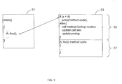
- Fig. 2 shows an inline cache.
- a method 51 was originally as follows:
- the method main includes a statement x.foo() in order to invoke the method foo of object x.
- the system would have to determine to which class object x belongs before the method to handle the method could be invoked.
- an inline cache the first time the system determines the class to which object x belongs, a direct call to the class's method is written into the computer code.
- the call x.foo() is changed to a direct call A::foo().
- the class of an object may be determined from a value stored in the object. If the object is of the correct class, a jump is performed to method code 57 that handles the message.
- a method lookup routine is called in order to determine the correct method. Once the correct method is found, the system updates the message dispatch (or call) site with a direct call to that method. Additionally, the system updates the prolog to specify the new class. As an example, assume that the first time that the system encountered x.foo (), object x was of class A and the data structures were modified as shown in Fig. 2.
- An inline cache may be an efficient way of implementing message dispatch if the object at a call site bar remains the same class. However, if the object is of multiple classes, the system is continually calling the method lookup routine and patching the call site and prolog. Thus, the system may be actually less efficient.
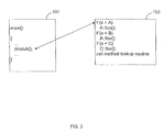
- a polymorphic inline cache as shown in Fig. 3.
- a method 101 originally included a method dispatch x.foo().
- a stub 103 is generated that is able to perform the message dispatch for different receiver types.
- the original message dispatch is overwritten with a call to the polymorphic inline cache stub 103.
- a statement is added to the stub.
- three different receiver types of have been encountered thus far. If the receiver type and has been encountered, a call is made to the method to handle the message for that receiver type. Otherwise, the method lookup routine is called to determine the appropriate method to handle the message.
- a new statement will be added to stub 103 in order to handle each new receiver type.
- the polymorphic inline cache is more flexible than the inline cache as it is able to handle multiple receiver types.
- a drawback of the polymorphic inline cache is that as more receiver types are encountered, the stub continues to grow and it becomes less and less efficient at performing message dispatch. For example, the system may need to plow through multiple if statements before finding the right method to handle the message.
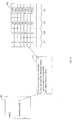
- Fig. 4 shows another message dispatch technique called hashing.
- hashing the original message dispatch in a method 151, x.foo(), is overwritten with a call to a hash function 153.
- the hash function hashes the receiver type and the message in order to form a hash key, which is typically an index into a hash table 155.
- the hash table includes an index 157, receiver types 159, messages 161, and methods 163. Once the hash function hashes to a row in cash table 155, the receiver type and message are retrieved from columns 159 and 161 of the hash table.
- the method specified in column 163 of hash table 155 is invoked. Otherwise, a method lookup routine is called in order to find the correct method. Typically, the new method is then added to the hash table.
- hashing is the most flexible message dispatch technique we have described thus far, it is more computationally and storage intensive then the other techniques.
- Another drawback of the message dispatch techniques we have described is that none of the techniques are site specific. In other words, none of the message dispatch techniques provide the flexibility of handling message dispatches at different call sites in a different manner.
- site specific message dispatch that is both efficient in terms of speed and computer code size. Additionally, there is a need for site specific message dispatch that is flexible and can adapt as the object-oriented program executes.
- Embodiments of the present invention provide innovative site specific message dispatch techniques that may be efficient in terms of speed and computer code size. By providing sites specific message dispatch techniques, message dispatch may be optimized for each message dispatch site. Therefore, instead of attempting to find one message dispatch technique that is efficient for all call sites, the technique may be adjusted to better accommodate the specific site. Several embodiments of the invention are described below.
- the invention provides a method of implementing message dispatch in an object-oriented environment.
- a predicted receiver type is saved at a site wherein a message is dispatched to a receiver object.
- the message is then sent to the receiver object.
- the receiver object Upon the receiver object receiving the message, it is verified that the receiver object is of the saved predicted receiver type.
- the predicted receiver type is saved into a register by a move instruction preceding the message dispatch instruction.
- the invention provides a method of implementing message dispatch in an object-oriented environment.
- a predicted receiver type is saved at a site where a message is dispatched to a receiver object.
- the message is then sent to the receiver object.
- it is verified that the receiver object is of the saved predicted receiver type. If the receiver object is not of the saved predicted receiver type, the predicted receiver type is changed to a type of the receiver object, a method lookup routine is called to obtain a new method, and the site is changed to invoke the new method.
- the invention provides a method of implementing message dispatch for an object-oriented program.
- a first message dispatch technique is performed at a specific site to dispatch messages to receiver objects.
- Dynamically during program execution it is determined if a second message dispatch technique is desirable at the specific site. If the second message dispatch technique is desirable, the second message dispatch technique is performed at the specific site to dispatch messages to the receiver objects. In preferred embodiments, it is determined that the second message dispatch technique is desirable if the specific site has dispatched messages to more than a predetermined number of different receiver object types.
- Fig. 1 illustrates a class hierarchy of classes including virtual functions in an object-oriented environment.
- Fig. 2 illustrates an inline cache technique for object-oriented message dispatch.
- Fig. 3 illustrates an a polymorphic inline cache technique for object-oriented message dispatch.
- Fig. 4 illustrates a hashing technique for object-oriented message dispatch.
- Fig. 5 illustrates an example of a computer system that may be utilized to execute the software of an embodiment of the invention.
- Fig. 6 illustrates a system block diagram of the computer system of Fig. 5.
- Fig. 7 illustrates how a Java source code program is executed.
- Fig. 8 illustrates an embodiment of a site specific inline cache technique for object-oriented message dispatch.
- Fig. 9 shows a high level flowchart of an embodiment of a site specific inline cache technique for object-oriented message dispatch.
- Fig. 10 shows a high level flowchart of an embodiment of a site specific message dispatch technique.
- Fig. 11 shows a flowchart of dynamically determining if another message dispatch technique is desirable at a specific site.
- Fig. 12 illustrates an embodiment of a site specific message dispatch technique that utilizes NOP instructions to count the number of different receiver types that have been encountered.
- Function - A software routine (also called a subroutine, procedure, member function, and method).
- Message dispatch - A process of determining the method to handle a message that has been sent to the object into an object-oriented environment.
- Receiver object (or receiver) - The object that has been sent a message in an object-oriented environment.
- Receiver type The class to which a receiver object belongs.
- Call site (or site) - The location or area in a program where a message is dispatched to an object.
- Fig. 5 illustrates an example of a computer system that may be used to execute the software of an embodiment of the invention.
- Fig. 5 shows a computer system 301 that includes a display 303, screen 305, cabinet 307, keyboard 309, and mouse 311.
- Mouse 311 may have one or more buttons for interacting with a graphical user interface.
- Cabinet 307 houses a CD-ROM drive 313, system memory and a hard drive ( see Fig. 6) which may be utilized to store and retrieve software programs incorporating computer code that implements the invention, data for use with the invention, and the like.
- CD-ROM 315 is shown as an exemplary computer readable storage medium, other computer readable storage media including floppy disk, tape, flash memory, system memory, and hard drive may be utilized.
- a data signal embodied in a carrier wave e.g., in a network including the Internet
- a carrier wave e.g., in a network including the Internet
- Fig. 6 shows a system block diagram of computer system 301 used to execute the software of an embodiment of the invention.
- computer system 301 includes monitor 303 and keyboard 309, and mouse 311.
- Computer system 301 further includes subsystems such as a central processor 351, system memory 353, fixed storage 355 (e.g., hard drive), removable storage 57 ( e.g., CD-ROM drive), display adapter 359, sound card 361, speakers 363, and network interface 365.
- Other computer systems suitable for use with the invention may include additional or fewer subsystems.
- another computer system could include more than one processor 351 (i.e., a multi-processor system) or a cache memory.
- the system bus architecture of computer system 301 is represented by arrows 367. However, these arrows are illustrative of any interconnection scheme serving to link the subsystems. For example, a local bus could be utilized to connect the central processor to the system memory and display adapter.
- Computer system 301 shown in Fig. 6 is but an example of a computer system suitable for use with the invention. Other computer architectures having different configurations of subsystems may also be utilized.
- JavaTM programming language was developed by Sun Microsystems. Typically, computer programs written in the Java programming language are compiled into bytecodes or Java virtual machine instructions that are then executed by a Java virtual machine. The bytecodes are stored in class files that are input into the Java virtual machine for interpretation.
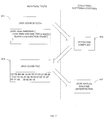
- Fig. 7 shows a progression of a simple piece of Java source code through execution by an interpreter, the Java virtual machine.
- Java source code 401 includes the classic Hello World program written in Java.
- the source code is then input into a bytecode compiler 403 that compiles the source code into bytecodes.
- the bytecodes are virtual machine instructions as they will be executed by a software emulated computer. Typically, virtual machine instructions are generic ( i.e., not designed for any specific microprocessor or computer architecture) but this is not required.
- the bytecode compiler outputs a Java class file 405 that includes the bytecodes for the Java program.
- the Java class file is input into a Java virtual machine 407.
- the Java virtual machine is an interpreter that decodes and executes the bytecodes in the Java class file.
- the Java virtual machine is an interpreter, but is commonly referred to as a virtual machine as it emulates a microprocessor or computer architecture in software (e.g., the microprocessor or computer architecture may not exist in hardware).
- methods may be compiled into native machine instructions for faster execution. In the description of preferred embodiments that follows, compilation will be used to refer to the translation of Java virtual machine instructions into native machine instructions.
- the invention provides a site specific inline cache technique for implementing message dispatch in object-oriented environments.
- Receiver type information is stored at the call site, which allows each call site to vary according to runtime characteristics of the call site. This allows message dispatch to not only be more efficient, but also to be more flexible.
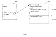
- Fig. 8 illustrates a site specific inline cash technique according to one embodiment of the invention.
- a method 51 originally included a message x.foo() for dispatch.
- the system may call a method lookup routine to determine the location of the appropriate method to handle the message.
- the system may perform a static analysis prior to runtime to determine what is likely to be the correct method.
- a site specific inline cache With a site specific inline cache, once the class of the object that should handle the message is determined, an instruction is generated at the call site to save the receiver type or class. The message dispatch is then overwritten with a call to the specific method that should handle the message. Thus, a message dispatch becomes two instructions, one that saves a receiver type and a call to the appropriate method.
- method 451 includes a move instruction that stores an id for the class A into a special register.
- the register is called a special register only for identification purposes. What is important is that if a register is utilized, the register should be otherwise unused at this call site.
- utilizing registers may provide the most efficient execution speed, other storage mechanisms may be utilized.
- the receiver type may be stored in system memory or sent as a parameter to the message handling method.
- a call is made to a method 453 that handles the message, which is shown as A::foo().
- a prolog 455 checks if the object x is of the saved receiver type, which is retrieved from the special register. In the example shown class A is the stored receiver type. Thus, if object x is of class A, a jump is made to a method code 457 of A::foo(). Otherwise, a method lookup routine is called to locate the appropriate method to handle the message. Then, the call site may be updated to save the receiver type of object x and a call to the method found by the method lookup routine.
- the receiver type stored at the call site is therefore a predicted receiver type. It is the receiver type that the system predicts will be the receiver type of the next object to receive the message. If the predicted receiver type matches the receiver type of the object, the message dispatch is more efficient. Additionally, each message dispatch site may have receiver type information stored that is particular to that call site and another site will not overwrite the stored receiver type information.
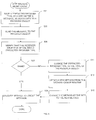
- Fig. 9 shows a flowchart of an embodiment of the site specific inline cache technique for message dispatch.
- a predicted receiver type is saved at a site where a message is dispatched to a receiver object.
- the receiver type is saved by utilizing a move instruction to place the receiver type in a register.
- other method of saving the receiver type may be utilized that are well known to those of skill in the art, including the use of system memory or parameter passing.
- the message is sent to the receiver object.
- the message is sent by a direct call to (or invocation of ) the method that handles the message instead of utilizing a method lookup routine.
- Step 505 the receiver object receives the message, it is verified that the receiver object is of the saved predicted receiver type at a step 505. In preferred embodiments, this verification is performed in the prolog of the method (see Fig. 8). If the receiver object is of the same type as the saved predicted receiver type at a step 507, the method that handles the message is executed at a step 509. Step 509 may include performing a jump to the start of the method code that handles the message.
- the predicted receiver type at the call site is changed to the receiver type of the receiver object at a step 511.
- the method lookup routine is called to obtain a new method at a step 513.
- the method lookup routine utilized may be any that are known to those of skill in the art, including dispatch table searches and virtual function tables.
- the method lookup routine provides the appropriate method to handle the message.
- the message dispatch at the call site is then changed to the method returned by the method lookup routine at a step 515.
- object x is of class A so the predicted receiver type stored at the call site in method 451 is class A.
- prolog 455 may modify the move instruction to store the class B in the special register as the predicted receiver type.
- the message dispatch will be modified to invoke the method returned by the method lookup routine. Subsequent message dispatches at this call site that are directed at a receiver object of class B will then be more efficiently dispatched.
- Fig. 9 the method is shown as being executed after step 515 that changes the method at the site.
- the step of executing the method may actually occur within step 513 or at other locations. Therefore, in the flowcharts shown, steps may be reordered, added and deleted according to the specific implementation without departing from the spirit of the invention.
- a site specific inline cache technique saves a predicted receiver type at a call site.
- message dispatch may be more efficient and flexible.
- the operations at each call site may be insulated from each other so that one call site will not change the settings for another call site.
- the invention provides a site specific message dispatch technique that is flexible in allowing for different message dispatch techniques to be utilized at each site. Additionally, the message dispatch technique utilized at a call site may change over time, during runtime. Once it is determined that a new or different message dispatch technique is desirable at a specific site, the new message dispatch technique is set up for use at the specific call site. Thus, message dispatch becomes more flexible not only in terms of call site, but also in terms of the message dispatch technique that is utilized at call during different times during program execution.
- Fig. 10 shows a high level flowchart of an embodiment of site specific message dispatch.
- a first message dispatch technique is performed at a specific message dispatch site.
- the first message dispatch technique may be any number of message dispatch techniques known in the art.
- the first message dispatch technique is a technique according to the present invention.
- the first message technique may be an embodiment of the site specific inline cache described above.
- the first message dispatch technique may be determine statically before runtime or dynamically during runtime.
- the system dynamically during runtime determines if a second message dispatch technique is desirable at the specific site. Any number ways may be utilized to determine that a second message dispatch technique is desirable. For example, once the number of different receiver types encountered at this call site crosses a threshold, it may be desirable to switch to a different message dispatch technique. Additionally, a calculation may be performed on the frequency that the method lookup routine is called so that if the frequency is too high, a new message dispatch may be warranted.
- the second message dispatch technique is performed at the specific site at a step 555.
- the mechanism for switching to a new message dispatch technique typically depends on the new technique itself. Now that the high level flow has been described, it may be beneficial to discuss in more detail an embodiment of the step of dynamically determining if a second message dispatch technique is desirable.
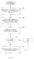
- Fig. 11 shows an embodiment of dynamically determining if a second message dispatch technique is desirable.
- the labels of first and second message dispatch techniques are presented as generic indications that one message dispatch technique may be switched to another at a specific call site. However, the invention is not limited to only two techniques, and may be advantageously applied to three or more techniques. Therefore, the labels of first and second are not an indication that the invention is limited to only two message dispatch techniques.
- Fig. 11 relies on the number of different receiver types encountered at a specific call site as an indicator of when the message dispatch should be changed.
- a site specific inline cache technique may be utilized until five different receiver types have been encountered at this call site.
- different receiver type is utilized in this context, it means that there have been five instances where the predicted receiver type has been different than the actual receiver type. This would mean that approximately five times, the method lookup routine has been called and the predicted receiver type that is stored at the call site has changed.
- a call site that alternates five times between receiver objects of classes A and B may be counted as five different receiver types.
- the counter is implemented as multiple no-operation (NOP) instructions preceding the method that handles the message.
- NOP no-operation
- the flowchart assumes that the method lookup routine has been called, otherwise, most likely, the current message dispatch technique is performing efficiently.
- the system dispatches messages to NOP instructions preceding the method that handles the message.
- the system counts the number of different receiver types by determining how many NOP instructions are executed before the method. Typically, this count will be determined by subtracting the address to where the message was dispatched for this site from the address of the actual method, including any prolog.
- the count is compared to a predetermined number.
- the predetermined number is the number of different receiver types that may be encountered at a call site before it is desirable to switch to a different message dispatch technique.
- the predetermined number may be statically defined or calculated dynamically during runtime.
- a switch is made to the second message dispatch technique at a step 609. If the count is less than or equal to the predetermined number, this indicates that, at present, it is not desirable to switch to the second message dispatch technique.
- An example may help in illustrating how NOP instructions may be utilized as a counter.
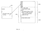
- Fig. 12 illustrates how NOP instructions may be utilized as a counter of the number of different receiver types that have been encountered at a specific call site.
- a method 651 is shown with a site specific inline cache as described previously.
- a method 653 handles the message, however, the method is preceded by a NOP section 655 that has multiple NOP instructions.
- NOP instructions may be chosen as they do nothing and may not unduly effect the operating speed of the method. Other instructions may be utilized instead of NOP instructions in other embodiments.
- NOP section 655 precedes a prolog 657 and method code 659 of method 653.
- the NOP section is composed of a predetermined number ofNOP instructions, typically the same number as the number of different receiver types that may be encountered at a call site before a switch to a different message dispatch technique is initiated.
- the move instruction is patched with the receiver type of object x.
- the subsequent message dispatch e.g., A::foo()
- the message dispatch points to the third NOP instruction before method 653. If prolog 657 determines that object x is not of class A, the prolog calculates the difference between the address specific at the call site and the beginning of method 653, which is obtainable during runtime by a number of known methods. The difference or count indicates the number of different receiver types that have been encountered at this specific call site. If the count is greater than a predetermined number, prolog 657 may switch the message dispatch technique utilized at this call site.
- NOP instructions in NOP section 655 may be referenced by multiple different call sites without any impact on each other.
- the first message dispatch technique was shown as being a site specific inline cache.
- the second message dispatch technique may be a polymorphic inline cache or hashing technique, as each are designed to handle multiple receiver types.
- the specific message dispatch techniques have been described herein to aid the reader's understanding.
- a site specific message dispatch technique is provided that allows for a new message dispatch technique to be utilized at a specific call site when it is deemed desirable. By allowing each call site to switch message dispatch techniques when it becomes desirable, message dispatch may be more efficient and flexible. Additionally, the operations at each call site may be insulated from each other so that one call site will not change the settings for another call site.
Abstract
Description
- The present invention relates to message dispatch in object-oriented systems. More specifically, the invention relates to site specific message dispatch techniques for the Java™ virtual machine.
- The fundamental idea behind object-oriented languages is the combination of both data and the methods (or functions) that operate on that data into a single unit, which is called an object. An object's functions typically provide the only way to access the data that is encapsulated by the object. The data is accessed by sending a message to the object instructing the object to invoke the method specified by the message.
- Efficient message dispatch is of paramount importance in object-oriented languages. This is because message dispatch is a very frequent operation in object-oriented programs and is performed at runtime; therefore, it should be as fast as possible. Message dispatch, however, is far from being a trivial operation. Unlike procedural programming languages (e.g., the C programming language) that can determine a function's address before runtime, object-oriented languages must determine the method that handles a message that has been dispatched to a receiver object at runtime, and it may involve an extensive search.
- In order to better understand the complexities of message dispatch, Fig. 1 shows a class hierarchy including methods of each class. A
class hierarchy 1 includes at its root a parent class A 3 that defines two virtual functions foo() and bar(). Virtual functions are functions that may be defined in a parent class and redefined in the children classes.Classes B 5 and class C 7 inherent the data and methods of the parent class A. As shown, class B does not redefine either of the virtual functions foo and bar. However, class C redefines the virtual function foo. When an object of class C is requested to invoke the method foo, the method invoked will be the method defined by the class C, not the parent classA. Classes D 9 and E 11 also redefine the method foo. - As it is generally impossible to determine the class of an object statically, the search for the correct method is performed at runtime, during message dispatch. There are many known techniques for implementing method dispatch. For example, Fig. 2 shows an inline cache. Assume a
method 51 was originally as follows:Thus, the method main includes a statement x.foo() in order to invoke the method foo of object x.
- During runtime, the system would have to determine to which class object x belongs before the method to handle the method could be invoked. With an inline cache, the first time the system determines the class to which object x belongs, a direct call to the class's method is written into the computer code.
- Assuming that object x is a member of class A, the call x.foo() is changed to a direct call A::foo(). The arrow specifies a method foo for
class A 53. Since the object x may not be of class A every time, aprolog 55 verifies that the object x is of the correct class, which is represented as the expression x=A meaning that it is determined if the class of object x is equal to class A. The class of an object may be determined from a value stored in the object. If the object is of the correct class, a jump is performed tomethod code 57 that handles the message. - Returning to
prolog 55, if the object is not of class A, a method lookup routine is called in order to determine the correct method. Once the correct method is found, the system updates the message dispatch (or call) site with a direct call to that method. Additionally, the system updates the prolog to specify the new class. As an example, assume that the first time that the system encountered x.foo (), object x was of class A and the data structures were modified as shown in Fig. 2. - Once the data structures are modified as shown, subsequent calls to x.foo() will be substantially more efficient if object x is of class A. However, if object x subsequently is of class B,
prolog 55 calls a method lookup routine to find the method and let's assume it determines that object x of now of class B. Referring again to Fig. 1, it is seen that the method foo for class B is the same method foo as defined in class A (i.e., class B did not redefine the virtual function foo). Accordingly, the message dispatch inmethod 51 will be changed to B::foo () and the condition inprolog 55 will be changed to x=B. - An inline cache may be an efficient way of implementing message dispatch if the object at a call site bar remains the same class. However, if the object is of multiple classes, the system is continually calling the method lookup routine and patching the call site and prolog. Thus, the system may be actually less efficient.
- Another technique for implementing message dispatch is the use a polymorphic inline cache as shown in Fig. 3. As before, a
method 101 originally included a method dispatch x.foo(). With a polymorphic inline cache, astub 103 is generated that is able to perform the message dispatch for different receiver types. The original message dispatch is overwritten with a call to the polymorphicinline cache stub 103. Each time a new receiver type is encountered, a statement is added to the stub. As shown, three different receiver types of have been encountered thus far. If the receiver type and has been encountered, a call is made to the method to handle the message for that receiver type. Otherwise, the method lookup routine is called to determine the appropriate method to handle the message. Typically, a new statement will be added tostub 103 in order to handle each new receiver type. - The polymorphic inline cache is more flexible than the inline cache as it is able to handle multiple receiver types. However, a drawback of the polymorphic inline cache is that as more receiver types are encountered, the stub continues to grow and it becomes less and less efficient at performing message dispatch. For example, the system may need to plow through multiple if statements before finding the right method to handle the message.
- Fig. 4 shows another message dispatch technique called hashing. In hashing, the original message dispatch in a
method 151, x.foo(), is overwritten with a call to ahash function 153. The hash function hashes the receiver type and the message in order to form a hash key, which is typically an index into a hash table 155. The hash table includes anindex 157,receiver types 159,messages 161, andmethods 163. Once the hash function hashes to a row in cash table 155, the receiver type and message are retrieved fromcolumns column 163 of hash table 155 is invoked. Otherwise, a method lookup routine is called in order to find the correct method. Typically, the new method is then added to the hash table. - Although hashing is the most flexible message dispatch technique we have described thus far, it is more computationally and storage intensive then the other techniques. Another drawback of the message dispatch techniques we have described is that none of the techniques are site specific. In other words, none of the message dispatch techniques provide the flexibility of handling message dispatches at different call sites in a different manner.
- Accordingly, there is a need for site specific message dispatch that is both efficient in terms of speed and computer code size. Additionally, there is a need for site specific message dispatch that is flexible and can adapt as the object-oriented program executes.
- Embodiments of the present invention provide innovative site specific message dispatch techniques that may be efficient in terms of speed and computer code size. By providing sites specific message dispatch techniques, message dispatch may be optimized for each message dispatch site. Therefore, instead of attempting to find one message dispatch technique that is efficient for all call sites, the technique may be adjusted to better accommodate the specific site. Several embodiments of the invention are described below.
- In one embodiment, the invention provides a method of implementing message dispatch in an object-oriented environment. A predicted receiver type is saved at a site wherein a message is dispatched to a receiver object. The message is then sent to the receiver object. Upon the receiver object receiving the message, it is verified that the receiver object is of the saved predicted receiver type. Typically, the predicted receiver type is saved into a register by a move instruction preceding the message dispatch instruction.
- In another embodiment, the invention provides a method of implementing message dispatch in an object-oriented environment. A predicted receiver type is saved at a site where a message is dispatched to a receiver object. The message is then sent to the receiver object. Upon the receiver object receiving the message, it is verified that the receiver object is of the saved predicted receiver type. If the receiver object is not of the saved predicted receiver type, the predicted receiver type is changed to a type of the receiver object, a method lookup routine is called to obtain a new method, and the site is changed to invoke the new method.
- In another embodiment, the invention provides a method of implementing message dispatch for an object-oriented program. A first message dispatch technique is performed at a specific site to dispatch messages to receiver objects. Dynamically during program execution, it is determined if a second message dispatch technique is desirable at the specific site. If the second message dispatch technique is desirable, the second message dispatch technique is performed at the specific site to dispatch messages to the receiver objects. In preferred embodiments, it is determined that the second message dispatch technique is desirable if the specific site has dispatched messages to more than a predetermined number of different receiver object types.
- Other features and advantages of the invention will become readily apparent upon review of the following detailed description in association with the accompanying drawings.
- Fig. 1 illustrates a class hierarchy of classes including virtual functions in an object-oriented environment.
- Fig. 2 illustrates an inline cache technique for object-oriented message dispatch.
- Fig. 3 illustrates an a polymorphic inline cache technique for object-oriented message dispatch.
- Fig. 4 illustrates a hashing technique for object-oriented message dispatch.
- Fig. 5 illustrates an example of a computer system that may be utilized to execute the software of an embodiment of the invention.
- Fig. 6 illustrates a system block diagram of the computer system of Fig. 5.
- Fig. 7 illustrates how a Java source code program is executed.
- Fig. 8 illustrates an embodiment of a site specific inline cache technique for object-oriented message dispatch.
- Fig. 9 shows a high level flowchart of an embodiment of a site specific inline cache technique for object-oriented message dispatch.
- Fig. 10 shows a high level flowchart of an embodiment of a site specific message dispatch technique.
- Fig. 11 shows a flowchart of dynamically determining if another message dispatch technique is desirable at a specific site.
- Fig. 12 illustrates an embodiment of a site specific message dispatch technique that utilizes NOP instructions to count the number of different receiver types that have been encountered.
- Function - A software routine (also called a subroutine, procedure, member function, and method).
- Message dispatch - A process of determining the method to handle a message that has been sent to the object into an object-oriented environment.
- Receiver object (or receiver) - The object that has been sent a message in an object-oriented environment.
- Receiver type - The class to which a receiver object belongs.
- Call site (or site) - The location or area in a program where a message is dispatched to an object.
- In the description that follows, the present invention will be described in reference to preferred embodiments that are designed for a Java™ virtual machine. In particular, examples will be described that are directed to IBM personal computers. However, the invention is not limited to any particular language, computer architecture, or specific implementation. Therefore, the description of the embodiments that follows for purposes of illustration and not limitation.
- Fig. 5 illustrates an example of a computer system that may be used to execute the software of an embodiment of the invention. Fig. 5 shows a
computer system 301 that includes adisplay 303,screen 305,cabinet 307,keyboard 309, andmouse 311.Mouse 311 may have one or more buttons for interacting with a graphical user interface.Cabinet 307 houses a CD-ROM drive 313, system memory and a hard drive (see Fig. 6) which may be utilized to store and retrieve software programs incorporating computer code that implements the invention, data for use with the invention, and the like. Although CD-ROM 315 is shown as an exemplary computer readable storage medium, other computer readable storage media including floppy disk, tape, flash memory, system memory, and hard drive may be utilized. Additionally, a data signal embodied in a carrier wave (e.g., in a network including the Internet) may be the computer readable storage medium. - Fig. 6 shows a system block diagram of
computer system 301 used to execute the software of an embodiment of the invention. As in Fig. 5,computer system 301 includesmonitor 303 andkeyboard 309, andmouse 311.Computer system 301 further includes subsystems such as acentral processor 351,system memory 353, fixed storage 355 (e.g., hard drive), removable storage 57 (e.g., CD-ROM drive),display adapter 359,sound card 361,speakers 363, andnetwork interface 365. Other computer systems suitable for use with the invention may include additional or fewer subsystems. For example, another computer system could include more than one processor 351 (i.e., a multi-processor system) or a cache memory. - The system bus architecture of
computer system 301 is represented byarrows 367. However, these arrows are illustrative of any interconnection scheme serving to link the subsystems. For example, a local bus could be utilized to connect the central processor to the system memory and display adapter.Computer system 301 shown in Fig. 6 is but an example of a computer system suitable for use with the invention. Other computer architectures having different configurations of subsystems may also be utilized. - The Java™ programming language was developed by Sun Microsystems. Typically, computer programs written in the Java programming language are compiled into bytecodes or Java virtual machine instructions that are then executed by a Java virtual machine. The bytecodes are stored in class files that are input into the Java virtual machine for interpretation. Fig. 7 shows a progression of a simple piece of Java source code through execution by an interpreter, the Java virtual machine.
-
Java source code 401 includes the classic Hello World program written in Java. The source code is then input into abytecode compiler 403 that compiles the source code into bytecodes. The bytecodes are virtual machine instructions as they will be executed by a software emulated computer. Typically, virtual machine instructions are generic (i.e., not designed for any specific microprocessor or computer architecture) but this is not required. The bytecode compiler outputs aJava class file 405 that includes the bytecodes for the Java program. - The Java class file is input into a Java
virtual machine 407. The Java virtual machine is an interpreter that decodes and executes the bytecodes in the Java class file. The Java virtual machine is an interpreter, but is commonly referred to as a virtual machine as it emulates a microprocessor or computer architecture in software (e.g., the microprocessor or computer architecture may not exist in hardware). In order to increase execution speed of the Java virtual machine, methods may be compiled into native machine instructions for faster execution. In the description of preferred embodiments that follows, compilation will be used to refer to the translation of Java virtual machine instructions into native machine instructions. - The invention provides a site specific inline cache technique for implementing message dispatch in object-oriented environments. Receiver type information is stored at the call site, which allows each call site to vary according to runtime characteristics of the call site. This allows message dispatch to not only be more efficient, but also to be more flexible.
- Fig. 8 illustrates a site specific inline cash technique according to one embodiment of the invention. As described in the above in the Background of the Invention, a
method 51 originally included a message x.foo() for dispatch. The first time that this message is dispatched, the system may call a method lookup routine to determine the location of the appropriate method to handle the message. Alternatively, the system may perform a static analysis prior to runtime to determine what is likely to be the correct method. - With a site specific inline cache, once the class of the object that should handle the message is determined, an instruction is generated at the call site to save the receiver type or class. The message dispatch is then overwritten with a call to the specific method that should handle the message. Thus, a message dispatch becomes two instructions, one that saves a receiver type and a call to the appropriate method.
- As shown,
method 451 includes a move instruction that stores an id for the class A into a special register. The register is called a special register only for identification purposes. What is important is that if a register is utilized, the register should be otherwise unused at this call site. Although utilizing registers may provide the most efficient execution speed, other storage mechanisms may be utilized. For example, the receiver type may be stored in system memory or sent as a parameter to the message handling method. - Once the receiver type is saved, a call is made to a
method 453 that handles the message, which is shown as A::foo(). Aprolog 455 checks if the object x is of the saved receiver type, which is retrieved from the special register. In the example shown class A is the stored receiver type. Thus, if object x is of class A, a jump is made to amethod code 457 of A::foo(). Otherwise, a method lookup routine is called to locate the appropriate method to handle the message. Then, the call site may be updated to save the receiver type of object x and a call to the method found by the method lookup routine. - The receiver type stored at the call site is therefore a predicted receiver type. It is the receiver type that the system predicts will be the receiver type of the next object to receive the message. If the predicted receiver type matches the receiver type of the object, the message dispatch is more efficient. Additionally, each message dispatch site may have receiver type information stored that is particular to that call site and another site will not overwrite the stored receiver type information.
- Fig. 9 shows a flowchart of an embodiment of the site specific inline cache technique for message dispatch. At a
step 501, a predicted receiver type is saved at a site where a message is dispatched to a receiver object. In preferred embodiments, the receiver type is saved by utilizing a move instruction to place the receiver type in a register. However, other method of saving the receiver type may be utilized that are well known to those of skill in the art, including the use of system memory or parameter passing. - At a
step 503, the message is sent to the receiver object. The message is sent by a direct call to (or invocation of ) the method that handles the message instead of utilizing a method lookup routine. - Once the receiver object receives the message, it is verified that the receiver object is of the saved predicted receiver type at a
step 505. In preferred embodiments, this verification is performed in the prolog of the method (see Fig. 8). If the receiver object is of the same type as the saved predicted receiver type at astep 507, the method that handles the message is executed at astep 509. Step 509 may include performing a jump to the start of the method code that handles the message. - If the receiver object is not of the same type as the saved predicted receiver type, the predicted receiver type at the call site is changed to the receiver type of the receiver object at a
step 511. The method lookup routine is called to obtain a new method at astep 513. The method lookup routine utilized may be any that are known to those of skill in the art, including dispatch table searches and virtual function tables. The method lookup routine provides the appropriate method to handle the message. The message dispatch at the call site is then changed to the method returned by the method lookup routine at astep 515. - As an example, assume that in Fig. 8, object x is of class A so the predicted receiver type stored at the call site in
method 451 is class A. However, if object x is subsequently of class B,prolog 455 may modify the move instruction to store the class B in the special register as the predicted receiver type. Additionally, the message dispatch will be modified to invoke the method returned by the method lookup routine. Subsequent message dispatches at this call site that are directed at a receiver object of class B will then be more efficiently dispatched. - In Fig. 9, the method is shown as being executed after
step 515 that changes the method at the site. The step of executing the method may actually occur withinstep 513 or at other locations. Therefore, in the flowcharts shown, steps may be reordered, added and deleted according to the specific implementation without departing from the spirit of the invention. - As described above, a site specific inline cache technique is provided that saves a predicted receiver type at a call site. By storing a predicted receiver type at a call site, message dispatch may be more efficient and flexible. For example, the operations at each call site may be insulated from each other so that one call site will not change the settings for another call site.
- The invention provides a site specific message dispatch technique that is flexible in allowing for different message dispatch techniques to be utilized at each site. Additionally, the message dispatch technique utilized at a call site may change over time, during runtime. Once it is determined that a new or different message dispatch technique is desirable at a specific site, the new message dispatch technique is set up for use at the specific call site. Thus, message dispatch becomes more flexible not only in terms of call site, but also in terms of the message dispatch technique that is utilized at call during different times during program execution.
- Fig. 10 shows a high level flowchart of an embodiment of site specific message dispatch. At a
step 511, a first message dispatch technique is performed at a specific message dispatch site. The first message dispatch technique may be any number of message dispatch techniques known in the art. Preferably, the first message dispatch technique is a technique according to the present invention. For example, the first message technique may be an embodiment of the site specific inline cache described above. The first message dispatch technique may be determine statically before runtime or dynamically during runtime. - At a
step 553, the system dynamically during runtime determines if a second message dispatch technique is desirable at the specific site. Any number ways may be utilized to determine that a second message dispatch technique is desirable. For example, once the number of different receiver types encountered at this call site crosses a threshold, it may be desirable to switch to a different message dispatch technique. Additionally, a calculation may be performed on the frequency that the method lookup routine is called so that if the frequency is too high, a new message dispatch may be warranted. - At any rate, once it is determined that a second message dispatch technique is desirable, the second message dispatch technique is performed at the specific site at a
step 555. The mechanism for switching to a new message dispatch technique typically depends on the new technique itself. Now that the high level flow has been described, it may be beneficial to discuss in more detail an embodiment of the step of dynamically determining if a second message dispatch technique is desirable. - Fig. 11 shows an embodiment of dynamically determining if a second message dispatch technique is desirable. The labels of first and second message dispatch techniques are presented as generic indications that one message dispatch technique may be switched to another at a specific call site. However, the invention is not limited to only two techniques, and may be advantageously applied to three or more techniques. Therefore, the labels of first and second are not an indication that the invention is limited to only two message dispatch techniques.
- The embodiment shown in Fig. 11 relies on the number of different receiver types encountered at a specific call site as an indicator of when the message dispatch should be changed. As an example, a site specific inline cache technique may be utilized until five different receiver types have been encountered at this call site. When different receiver type is utilized in this context, it means that there have been five instances where the predicted receiver type has been different than the actual receiver type. This would mean that approximately five times, the method lookup routine has been called and the predicted receiver type that is stored at the call site has changed. As an example, a call site that alternates five times between receiver objects of classes A and B may be counted as five different receiver types.
- Although a specific receiver type counter may be utilized at each call site, this may entail the use of memory and computer code to maintain the counter. In preferred embodiments, the counter is implemented as multiple no-operation (NOP) instructions preceding the method that handles the message. As will be described in more detail in reference to Fig. 12, the number NOP instructions that implemented before the method indicates the number of different receiver types that have been encountered.
- Referring to Fig. 11, the flowchart assumes that the method lookup routine has been called, otherwise, most likely, the current message dispatch technique is performing efficiently. At a
step 601, the system dispatches messages to NOP instructions preceding the method that handles the message. The system counts the number of different receiver types by determining how many NOP instructions are executed before the method. Typically, this count will be determined by subtracting the address to where the message was dispatched for this site from the address of the actual method, including any prolog. - At a
step 605, the count is compared to a predetermined number. The predetermined number is the number of different receiver types that may be encountered at a call site before it is desirable to switch to a different message dispatch technique. The predetermined number may be statically defined or calculated dynamically during runtime. - If the count is greater than the predetermined number at a
step 607, a switch is made to the second message dispatch technique at astep 609. If the count is less than or equal to the predetermined number, this indicates that, at present, it is not desirable to switch to the second message dispatch technique. An example may help in illustrating how NOP instructions may be utilized as a counter. - Fig. 12 illustrates how NOP instructions may be utilized as a counter of the number of different receiver types that have been encountered at a specific call site. A
method 651 is shown with a site specific inline cache as described previously. Amethod 653 handles the message, however, the method is preceded by aNOP section 655 that has multiple NOP instructions. NOP instructions may be chosen as they do nothing and may not unduly effect the operating speed of the method. Other instructions may be utilized instead of NOP instructions in other embodiments. -
NOP section 655 precedes aprolog 657 andmethod code 659 ofmethod 653. The NOP section is composed of a predetermined number ofNOP instructions, typically the same number as the number of different receiver types that may be encountered at a call site before a switch to a different message dispatch technique is initiated. Each time the method lookup routine is called inprolog 657, the move instruction is patched with the receiver type of object x. Additionally, the subsequent message dispatch (e.g., A::foo()) is changed to one of the NOP instructions inNOP section 655 of the new method found by the method lookup routine. - As shown, the message dispatch points to the third NOP instruction before
method 653. Ifprolog 657 determines that object x is not of class A, the prolog calculates the difference between the address specific at the call site and the beginning ofmethod 653, which is obtainable during runtime by a number of known methods. The difference or count indicates the number of different receiver types that have been encountered at this specific call site. If the count is greater than a predetermined number,prolog 657 may switch the message dispatch technique utilized at this call site. - Utilizing NOP instructions before a method is easy to implement, fast, and does not require an excessive amount of computer code to keep the counter. Additionally, the NOP instructions in
NOP section 655 may be referenced by multiple different call sites without any impact on each other. - The first message dispatch technique was shown as being a site specific inline cache. The second message dispatch technique may be a polymorphic inline cache or hashing technique, as each are designed to handle multiple receiver types. Of course, there is no limitation on the message dispatch techniques that may be utilized with the invention. The specific message dispatch techniques have been described herein to aid the reader's understanding.
- As described above, a site specific message dispatch technique is provided that allows for a new message dispatch technique to be utilized at a specific call site when it is deemed desirable. By allowing each call site to switch message dispatch techniques when it becomes desirable, message dispatch may be more efficient and flexible. Additionally, the operations at each call site may be insulated from each other so that one call site will not change the settings for another call site.
- While the above is a complete description of preferred embodiments of the invention, there is alternatives, modifications, and equivalents may be used. It should be evident that the invention is equally applicable by making appropriate modifications to the embodiments described above. For example, the site specific message dispatch techniques may be advantageously applied to object-oriented languages without departing from the spirit of the invention. Therefore, the above description should not be taken as limiting the scope of the invention that is defined by the meets and bounds of the impended claims along with their full scope of equivalents.
Claims (29)
- In a computer system, a method of implementing message dispatch in an object-oriented environment, comprising:saving a predicted receiver type at a site where a message is dispatched to a receiver object;sending the message to the receiver object; andupon the receiver object receiving the message, verifying that the receiver object is of the saved predicted receiver type.
- The method of claim 1, wherein saving a predicted receiver type includes storing the predicted receiver type into a register.
- The method of claim 2, wherein a move instruction preceding the site where a message is dispatched is utilized to store the predicted receiver type into the register.
- The method of claim 1, wherein saving a predicted receiver type includes storing the predicted receiver type in a memory location.
- The method of claim 1, wherein saving a predicted receiver type includes passing the predicted receiver type to the receiver object as a parameter of the message.
- The method of any one of the preceding claims, further comprising changing the predicted receiver type to a type of the receiver object if the receiver object is not of the saved predicted receiver type.
- The method of any one of the preceding claims, further comprising calling a method lookup routine to obtain a new method from the method lookup routine.
- The method of claim 7, further comprising changing the site to invoke the new method.
- The method of any one of the preceding claims, wherein the verifying the receiver object includes:obtaining a receiver type of the receiver object; andcomparing the receiver type of the receiver object to the saved predicted receiver type.
- The method of claim 9, further comprising changing the predicted receiver type to the receiver type of the receiver object if the receiver type is not equal to the saved predicted receiver type.
- The method of any one of claims 9 and 10, further comprising calling a method lookup routine if the receiver type of the receiver object is not equal to the saved predicted receiver type.
- The method of claim 11, further comprising obtaining a new method from the method lookup routine.
- The method of claim 12, further comprising changing the site to invoke the new method.
- A computer program product that implements message dispatch in an object-oriented environment, comprising:computer code that saves a predicted receiver type at a site where a message is dispatched to a receiver object;computer code that sends the message to the receiver object;computer code that upon the receiver object receiving the message, verifies that the receiver object is of the saved predicted receiver type; anda computer readable medium that stores the computer code.
- The computer program product of claim 14, wherein the computer readable medium is selected from the group consisting of CD-ROM, floppy disk, tape, flash memory, system memory, hard drive, and data signal embodied in a carrier wave.
- A computer system that implements message dispatch in an object-oriented environment, comprising:a processor that executes computer code;computer code that saves a predicted receiver type at a site where a message is dispatched to a receiver object;computer code that sends the message to the receiver object;computer code that upon the receiver object receiving the message, verifies that the receiver object is of the saved predicted receiver type; anda computer readable medium that stores the computer code for the processor to execute.
- In a computer system, a method of implementing message dispatch in an object-oriented environment, comprising:saving a predicted receiver type at a site where a message is dispatched to a receiver object;sending the message to the receiver object;upon the receiver object receiving the message, verifying that the receiver object is of the saved predicted receiver type;changing the predicted receiver type to a type of the receiver object if the receiver object is not of the saved predicted receiver type;calling a method lookup routine to obtain a new method if the receiver object is not of the saved predicted receiver type; andchanging the site to invoke the new method.
- The method of claim 17, wherein saving a predicted receiver type includes one selected from the group consisting of moving the predicted receiver type into a register, storing the predicted receiver type into a register, and passing the predicted receiver type to the receiver object as a parameter of the message.
- The method of any one of claims 17 and 18, wherein the verifying the receiver object includes:obtaining a receiver type of the receiver object; andcomparing the receiver type of the receiver object to the saved predicted receiver type.
- A computer program product that implements message dispatch in an object-oriented environment, comprising:computer code that saves a predicted receiver type at a site where a message is dispatched to a receiver object;computer code that sends the message to the receiver object;computer code that upon the receiver object receiving the message, verifies that the receiver object is of the saved predicted receiver type;computer code that changes the predicted receiver type to a type of the receiver object if the receiver object is not of the saved predicted receiver type;computer code that calls a method lookup routine to obtain a new method if the receiver object is not of the saved predicted receiver type; andcomputer code that changes the site to invoke the new method; anda computer readable medium that stores the computer code.
- The computer program product of claim 20, wherein the computer readable medium is selected from the group consisting of CD-ROM, floppy disk, tape, flash memory, system memory, hard drive, and data signal embodied in a carrier wave.
- A computer system that implements message dispatch in an object-oriented environment, comprising:a processor that executes computer code;computer code that saves a predicted receiver type at a site where a message is dispatched to a receiver object;computer code that sends the message to the receiver object;computer code that upon the receiver object receiving the message, verifies that the receiver object is of the saved predicted receiver type;computer code that changes the predicted receiver type to a type of the receiver object if the receiver object is not of the saved predicted receiver type;computer code that calls a method lookup routine to obtain a new method if the receiver object is not of the saved predicted receiver type;computer code that changes the site to invoke the new method; anda computer readable medium that stores the computer code for the processor to execute.
- In a computer system, a method of implementing message dispatch for an object-oriented program, comprising:performing a first message dispatch technique at a specific site to dispatch messages to receiver objects;dynamically determining during program execution if a second message dispatch technique is desirable at the specific site; andperforming the second message dispatch technique at the specific site to dispatch messages to the receiver objects if the second message dispatch technique is desirable.
- The method of claim 23, wherein the determining during program execution if a second message dispatch technique is desirable includes determining if the specific site has dispatched messages to more than a first predetermined number of different receiver types.
- The method of claim 24, further comprising maintaining a count of different receiver types to which the first dispatch technique has dispatched messages.
- The method of any one of claims 23-25, wherein the first message dispatch technique is determined statically before program execution.
- The method of any one of claims 23-25, wherein the first message dispatch technique is inline caching.
- The method of any one of claims 23-27, wherein the second message dispatch technique is selected from polymorphic inline caching and hashing.
- A computer system that implements message dispatch for an object-oriented program, comprising:a processor that executes computer code;computer code that performs a first message dispatch technique at a specific site to dispatch messages to receiver objects;computer code that dynamically determines during program execution if a second message dispatch technique is desirable at the specific site; andcomputer code that subsequently performs the second message dispatch technique at the specific site to dispatch messages to the receiver objects if the second message dispatch technique is desirable; anda computer readable medium that stores the computer code for the processor to execute.
Applications Claiming Priority (2)
| Application Number | Priority Date | Filing Date | Title |
|---|---|---|---|
| US08/944,331 US6385660B2 (en) | 1997-10-06 | 1997-10-06 | Site specific message dispatch in object-oriented systems |
| US944331 | 1997-10-06 |
Publications (2)
| Publication Number | Publication Date |
|---|---|
| EP0908814A1 true EP0908814A1 (en) | 1999-04-14 |
| EP0908814B1 EP0908814B1 (en) | 2002-06-05 |
Family
ID=25481206
Family Applications (1)
| Application Number | Title | Priority Date | Filing Date |
|---|---|---|---|
| EP98307753A Expired - Lifetime EP0908814B1 (en) | 1997-10-06 | 1998-09-24 | Site specific message dispatch in object-oriented systems |
Country Status (6)
| Country | Link |
|---|---|
| US (1) | US6385660B2 (en) |
| EP (1) | EP0908814B1 (en) |
| JP (1) | JPH11272468A (en) |
| KR (1) | KR19990037014A (en) |
| CN (1) | CN1105968C (en) |
| DE (1) | DE69805728T2 (en) |
Families Citing this family (44)
| Publication number | Priority date | Publication date | Assignee | Title |
|---|---|---|---|---|
| US6317796B1 (en) * | 1997-10-06 | 2001-11-13 | Sun Microsystems, Inc. | Inline database for receiver types in object-oriented systems |
| US7966234B1 (en) | 1999-05-17 | 2011-06-21 | Jpmorgan Chase Bank. N.A. | Structured finance performance analytics system |
| US7234146B1 (en) * | 1999-07-30 | 2007-06-19 | International Business Machines Corporation | Object in, object out technique |
| US7249095B2 (en) | 2000-06-07 | 2007-07-24 | The Chase Manhattan Bank, N.A. | System and method for executing deposit transactions over the internet |
| US6779188B1 (en) * | 2000-09-28 | 2004-08-17 | International Business Machines Corporation | Apparatus and method for improved devirtualization of method calls |
| US6912647B1 (en) | 2000-09-28 | 2005-06-28 | International Business Machines Corportion | Apparatus and method for creating instruction bundles in an explicitly parallel architecture |
| US6799262B1 (en) | 2000-09-28 | 2004-09-28 | International Business Machines Corporation | Apparatus and method for creating instruction groups for explicity parallel architectures |
| US6886094B1 (en) | 2000-09-28 | 2005-04-26 | International Business Machines Corporation | Apparatus and method for detecting and handling exceptions |
| US6883165B1 (en) | 2000-09-28 | 2005-04-19 | International Business Machines Corporation | Apparatus and method for avoiding deadlocks in a multithreaded environment |
| US6779106B1 (en) | 2000-09-28 | 2004-08-17 | International Business Machines Corporation | Apparatus and method for an enhanced integer divide in an IA64 architecture |
| US7313541B2 (en) | 2000-11-03 | 2007-12-25 | Jpmorgan Chase Bank, N.A. | System and method for estimating conduit liquidity requirements in asset backed commercial paper |
| US7984147B2 (en) * | 2000-12-29 | 2011-07-19 | Hewlett-Packard Development Company, L.P. | Apparatus and method for identifying a requested level of service for a transaction |
| US7596526B2 (en) * | 2001-04-16 | 2009-09-29 | Jpmorgan Chase Bank, N.A. | System and method for managing a series of overnight financing trades |
| DE10131944A1 (en) * | 2001-07-02 | 2003-01-16 | Siemens Ag | Processes for processing data |
| US8224723B2 (en) | 2002-05-31 | 2012-07-17 | Jpmorgan Chase Bank, N.A. | Account opening system, method and computer program product |
| CN1464401B (en) * | 2002-06-28 | 2010-05-26 | 国际商业机器公司 | Object oriented system and method using shadow object for verification control |
| US20050044033A1 (en) * | 2003-01-10 | 2005-02-24 | Gelson Andrew F. | Like-kind exchange method |
| US20040148247A1 (en) * | 2003-01-24 | 2004-07-29 | Lawrence Miller | Network-based systems, methods, and software for initiating or executing financial transactions |
| US7634435B2 (en) * | 2003-05-13 | 2009-12-15 | Jp Morgan Chase Bank | Diversified fixed income product and method for creating and marketing same |
| US7770184B2 (en) * | 2003-06-06 | 2010-08-03 | Jp Morgan Chase Bank | Integrated trading platform architecture |
| US20050015324A1 (en) * | 2003-07-15 | 2005-01-20 | Jacob Mathews | Systems and methods for trading financial instruments across different types of trading platforms |
| US7970688B2 (en) * | 2003-07-29 | 2011-06-28 | Jp Morgan Chase Bank | Method for pricing a trade |
| US20050060256A1 (en) * | 2003-09-12 | 2005-03-17 | Andrew Peterson | Foreign exchange trading interface |
| US20050222937A1 (en) * | 2004-03-31 | 2005-10-06 | Coad Edward J | Automated customer exchange |
| US8423447B2 (en) * | 2004-03-31 | 2013-04-16 | Jp Morgan Chase Bank | System and method for allocating nominal and cash amounts to trades in a netted trade |
| US20050251478A1 (en) * | 2004-05-04 | 2005-11-10 | Aura Yanavi | Investment and method for hedging operational risk associated with business events of another |
| US7693770B2 (en) | 2004-08-06 | 2010-04-06 | Jp Morgan Chase & Co. | Method and system for creating and marketing employee stock option mirror image warrants |
| US20090164384A1 (en) * | 2005-02-09 | 2009-06-25 | Hellen Patrick J | Investment structure and method for reducing risk associated with withdrawals from an investment |
| US8688569B1 (en) | 2005-03-23 | 2014-04-01 | Jpmorgan Chase Bank, N.A. | System and method for post closing and custody services |
| US20060242654A1 (en) * | 2005-04-22 | 2006-10-26 | Lund Kasper V | Process and apparatus for sharing inline caches |
| US20090187512A1 (en) * | 2005-05-31 | 2009-07-23 | Jp Morgan Chase Bank | Asset-backed investment instrument and related methods |
| US7822682B2 (en) | 2005-06-08 | 2010-10-26 | Jpmorgan Chase Bank, N.A. | System and method for enhancing supply chain transactions |
| US20110035306A1 (en) * | 2005-06-20 | 2011-02-10 | Jpmorgan Chase Bank, N.A. | System and method for buying and selling securities |
| US7567928B1 (en) | 2005-09-12 | 2009-07-28 | Jpmorgan Chase Bank, N.A. | Total fair value swap |
| US7818238B1 (en) | 2005-10-11 | 2010-10-19 | Jpmorgan Chase Bank, N.A. | Upside forward with early funding provision |
| US8280794B1 (en) | 2006-02-03 | 2012-10-02 | Jpmorgan Chase Bank, National Association | Price earnings derivative financial product |
| US8291395B2 (en) * | 2006-03-31 | 2012-10-16 | Apple Inc. | Fast function call dispatching |
| US7620578B1 (en) | 2006-05-01 | 2009-11-17 | Jpmorgan Chase Bank, N.A. | Volatility derivative financial product |
| US7647268B1 (en) | 2006-05-04 | 2010-01-12 | Jpmorgan Chase Bank, N.A. | System and method for implementing a recurrent bidding process |
| US9811868B1 (en) | 2006-08-29 | 2017-11-07 | Jpmorgan Chase Bank, N.A. | Systems and methods for integrating a deal process |
| US7827096B1 (en) | 2006-11-03 | 2010-11-02 | Jp Morgan Chase Bank, N.A. | Special maturity ASR recalculated timing |
| US8307379B2 (en) | 2006-12-21 | 2012-11-06 | International Business Machines Corporation | Determining an extension to use to process an input object to a call in a program |
| US8738514B2 (en) | 2010-02-18 | 2014-05-27 | Jpmorgan Chase Bank, N.A. | System and method for providing borrow coverage services to short sell securities |
| US8352354B2 (en) | 2010-02-23 | 2013-01-08 | Jpmorgan Chase Bank, N.A. | System and method for optimizing order execution |
Citations (2)
| Publication number | Priority date | Publication date | Assignee | Title |
|---|---|---|---|---|
| EP0546684A2 (en) * | 1991-12-12 | 1993-06-16 | International Business Machines Corporation | Method stubs for redispatch |
| US5600838A (en) * | 1994-01-18 | 1997-02-04 | Sybase, Inc. | Object oriented dispatch and supercall process and arrangement |
Family Cites Families (13)
| Publication number | Priority date | Publication date | Assignee | Title |
|---|---|---|---|---|
| US5297284A (en) | 1991-04-09 | 1994-03-22 | Microsoft Corporation | Method and system for implementing virtual functions and virtual base classes and setting a this pointer for an object-oriented programming language |
| US5361350A (en) | 1991-12-12 | 1994-11-01 | International Business Machines Corporation | Object oriented method management system and software for managing class method names in a computer system |
| US5404525A (en) | 1992-09-30 | 1995-04-04 | International Business Machines Corporation | Efficient method router that supports multiple simultaneous object versions |
| US5442793A (en) | 1993-02-26 | 1995-08-15 | Microsoft Corporation | Method and system for locating an inherited virtual function member of a derived class |
| US5485617A (en) | 1993-12-13 | 1996-01-16 | Microsoft Corporation | Method and system for dynamically generating object connections |
| US5522071A (en) * | 1994-01-18 | 1996-05-28 | Sybase, Inc. | Run-time message redirection for invoking object oriented methods based on alternate dispatch variable |
| US5581697A (en) * | 1994-01-28 | 1996-12-03 | Sun Microsystems, Inc. | Method and apparatus for run-time error checking using dynamic patching |
| US5682532A (en) | 1994-05-02 | 1997-10-28 | Microsoft Corporation | System and method having programmable containers with functionality for managing objects |
| US5794044A (en) | 1995-12-08 | 1998-08-11 | Sun Microsystems, Inc. | System and method for runtime optimization of private variable function calls in a secure interpreter |
| JPH09282167A (en) * | 1996-04-10 | 1997-10-31 | Internatl Business Mach Corp <Ibm> | Method activation method and method activation controller |
| US5960197A (en) * | 1996-05-09 | 1999-09-28 | Sun Microsystems, Inc. | Compiler dispatch function for object-oriented C |
| US5884316A (en) | 1996-11-19 | 1999-03-16 | Microsoft Corporation | Implicit session context system with object state cache |
| US5907707A (en) | 1997-01-14 | 1999-05-25 | International Business Machines Corporation | Object model for Java |
-
1997
- 1997-10-06 US US08/944,331 patent/US6385660B2/en not_active Expired - Lifetime
-
1998
- 1998-09-24 DE DE69805728T patent/DE69805728T2/en not_active Expired - Lifetime
- 1998-09-24 EP EP98307753A patent/EP0908814B1/en not_active Expired - Lifetime
- 1998-10-05 CN CN98124353A patent/CN1105968C/en not_active Expired - Fee Related
- 1998-10-06 JP JP10319741A patent/JPH11272468A/en active Pending
- 1998-10-07 KR KR1019980042466A patent/KR19990037014A/en active IP Right Grant
Patent Citations (2)
| Publication number | Priority date | Publication date | Assignee | Title |
|---|---|---|---|---|
| EP0546684A2 (en) * | 1991-12-12 | 1993-06-16 | International Business Machines Corporation | Method stubs for redispatch |
| US5600838A (en) * | 1994-01-18 | 1997-02-04 | Sybase, Inc. | Object oriented dispatch and supercall process and arrangement |
Non-Patent Citations (1)
| Title |
|---|
| PLEVYAK J ET AL: "TYPE DIRECTED CLONING FOR OBJECT ORIENTED PROGRAMS", LANGUAGES AND COMPILERS FOR PARALLEL COMPUTING, 8TH. INTERNATIONAL WORKSHOP, LCPC '95 COLUMBUS, AUG. 10 - 12, 1995, no. WORKSHOP 8, 10 August 1995 (1995-08-10), HUANG C -H ET AL (ED ), pages 566 - 580, XP000689171 * |
Also Published As
| Publication number | Publication date |
|---|---|
| JPH11272468A (en) | 1999-10-08 |
| KR19990037014A (en) | 1999-05-25 |
| US6385660B2 (en) | 2002-05-07 |
| EP0908814B1 (en) | 2002-06-05 |
| DE69805728D1 (en) | 2002-07-11 |
| US20010011306A1 (en) | 2001-08-02 |
| CN1105968C (en) | 2003-04-16 |
| DE69805728T2 (en) | 2003-01-30 |
| CN1233797A (en) | 1999-11-03 |
Similar Documents
| Publication | Publication Date | Title |
|---|---|---|
| EP0908814B1 (en) | Site specific message dispatch in object-oriented systems | |
| EP0908815B1 (en) | Inline database for receiver types in object-oriented systems | |
| US6192516B1 (en) | Interpreter generation and implementation utilizing interpreter states and register caching | |
| US6910205B2 (en) | Interpreting functions utilizing a hybrid of virtual and native machine instructions | |
| US6651080B1 (en) | Techniques for implementing pluggable virtual machines | |
| US6968546B2 (en) | Debugging support using dynamic re-compilation | |
| US6453411B1 (en) | System and method using a hardware embedded run-time optimizer | |
| US6148437A (en) | System and method for jump-evaluated trace designation | |
| US8104035B2 (en) | Program for controlling a virtual computer and computer system for virtulization technology | |
| US6966057B2 (en) | Static compilation of instrumentation code for debugging support | |
| AU774467B2 (en) | Automatic stub/adapter generator | |
| JP3894698B2 (en) | A hybrid just-in-time compiler that minimizes resource consumption | |
| EP0997816B1 (en) | Method and apparatus for selecting ways to compile at runtime | |
| US6122638A (en) | Object-oriented processor and method for caching intermediate data in an object-oriented processor | |
| US6704927B1 (en) | Static binding of dynamically-dispatched calls in the presence of dynamic linking and loading | |
| US20040123278A1 (en) | Persistent cache apparatus and methods | |
| JP2003140909A (en) | Virtual computer having jit compiler | |
| US6173248B1 (en) | Method and apparatus for handling masked exceptions in an instruction interpreter | |
| US7194735B2 (en) | Executing native code in place of non-native code | |
| JPH09198255A (en) | Method for storing and restoring emulation context exerting no effect on operating system and system therefor | |
| US20080052691A1 (en) | Communicating with and recovering state information from a dynamic translator | |
| JP5129904B2 (en) | Method for increasing function execution performance during execution, computer system, and computer-readable medium storing a computer program for increasing function execution performance during execution | |
| US6853868B1 (en) | Cross-platform audio feedback for GUI components |
Legal Events
| Date | Code | Title | Description |
|---|---|---|---|
| PUAI | Public reference made under article 153(3) epc to a published international application that has entered the european phase |
Free format text: ORIGINAL CODE: 0009012 |
|
| AK | Designated contracting states |
Kind code of ref document: A1 Designated state(s): DE FR GB NL SE |
|
| AX | Request for extension of the european patent |
Free format text: AL;LT;LV;MK;RO;SI |
|
| 17P | Request for examination filed |
Effective date: 19990512 |
|
| AKX | Designation fees paid |
Free format text: DE FR GB NL SE |
|
| 17Q | First examination report despatched |
Effective date: 20001123 |
|
| GRAG | Despatch of communication of intention to grant |
Free format text: ORIGINAL CODE: EPIDOS AGRA |
|
| GRAG | Despatch of communication of intention to grant |
Free format text: ORIGINAL CODE: EPIDOS AGRA |
|
| GRAG | Despatch of communication of intention to grant |
Free format text: ORIGINAL CODE: EPIDOS AGRA |
|
| GRAH | Despatch of communication of intention to grant a patent |
Free format text: ORIGINAL CODE: EPIDOS IGRA |
|
| GRAH | Despatch of communication of intention to grant a patent |
Free format text: ORIGINAL CODE: EPIDOS IGRA |
|
| GRAA | (expected) grant |
Free format text: ORIGINAL CODE: 0009210 |
|
| AK | Designated contracting states |
Kind code of ref document: B1 Designated state(s): DE FR GB NL SE |
|
| REG | Reference to a national code |
Ref country code: GB Ref legal event code: FG4D |
|
| REF | Corresponds to: |
Ref document number: 69805728 Country of ref document: DE Date of ref document: 20020711 |
|
| ET | Fr: translation filed | ||
| PLBE | No opposition filed within time limit |
Free format text: ORIGINAL CODE: 0009261 |
|
| STAA | Information on the status of an ep patent application or granted ep patent |
Free format text: STATUS: NO OPPOSITION FILED WITHIN TIME LIMIT |
|
| 26N | No opposition filed |
Effective date: 20030306 |
|
| PGFP | Annual fee paid to national office [announced via postgrant information from national office to epo] |
Ref country code: FR Payment date: 20030925 Year of fee payment: 6 |
|
| PGFP | Annual fee paid to national office [announced via postgrant information from national office to epo] |
Ref country code: SE Payment date: 20030926 Year of fee payment: 6 |
|
| PGFP | Annual fee paid to national office [announced via postgrant information from national office to epo] |
Ref country code: NL Payment date: 20030930 Year of fee payment: 6 |
|
| PG25 | Lapsed in a contracting state [announced via postgrant information from national office to epo] |
Ref country code: SE Free format text: LAPSE BECAUSE OF NON-PAYMENT OF DUE FEES Effective date: 20040925 |
|
| PG25 | Lapsed in a contracting state [announced via postgrant information from national office to epo] |
Ref country code: NL Free format text: LAPSE BECAUSE OF NON-PAYMENT OF DUE FEES Effective date: 20050401 |
|
| EUG | Se: european patent has lapsed | ||
| PG25 | Lapsed in a contracting state [announced via postgrant information from national office to epo] |
Ref country code: FR Free format text: LAPSE BECAUSE OF NON-PAYMENT OF DUE FEES Effective date: 20050531 |
|
| NLV4 | Nl: lapsed or anulled due to non-payment of the annual fee |
Effective date: 20050401 |
|
| REG | Reference to a national code |
Ref country code: FR Ref legal event code: ST |
|
| PGFP | Annual fee paid to national office [announced via postgrant information from national office to epo] |
Ref country code: GB Payment date: 20060920 Year of fee payment: 9 |
|
| GBPC | Gb: european patent ceased through non-payment of renewal fee |
Effective date: 20070924 |
|
| PG25 | Lapsed in a contracting state [announced via postgrant information from national office to epo] |
Ref country code: GB Free format text: LAPSE BECAUSE OF NON-PAYMENT OF DUE FEES Effective date: 20070924 |
|
| PGFP | Annual fee paid to national office [announced via postgrant information from national office to epo] |
Ref country code: DE Payment date: 20170920 Year of fee payment: 20 |
|
| REG | Reference to a national code |
Ref country code: DE Ref legal event code: R071 Ref document number: 69805728 Country of ref document: DE |