EP0854607A1 - Method for planning and configuring a communications network - Google Patents
Method for planning and configuring a communications network Download PDFInfo
- Publication number
- EP0854607A1 EP0854607A1 EP98100787A EP98100787A EP0854607A1 EP 0854607 A1 EP0854607 A1 EP 0854607A1 EP 98100787 A EP98100787 A EP 98100787A EP 98100787 A EP98100787 A EP 98100787A EP 0854607 A1 EP0854607 A1 EP 0854607A1
- Authority
- EP
- European Patent Office
- Prior art keywords
- plan
- configuration
- network
- target
- database
- Prior art date
- Legal status (The legal status is an assumption and is not a legal conclusion. Google has not performed a legal analysis and makes no representation as to the accuracy of the status listed.)
- Withdrawn
Links
Images


Classifications
-
- H—ELECTRICITY
- H04—ELECTRIC COMMUNICATION TECHNIQUE
- H04L—TRANSMISSION OF DIGITAL INFORMATION, e.g. TELEGRAPHIC COMMUNICATION
- H04L41/00—Arrangements for maintenance, administration or management of data switching networks, e.g. of packet switching networks
- H04L41/02—Standardisation; Integration
- H04L41/0213—Standardised network management protocols, e.g. simple network management protocol [SNMP]
-
- H—ELECTRICITY
- H04—ELECTRIC COMMUNICATION TECHNIQUE
- H04L—TRANSMISSION OF DIGITAL INFORMATION, e.g. TELEGRAPHIC COMMUNICATION
- H04L41/00—Arrangements for maintenance, administration or management of data switching networks, e.g. of packet switching networks
- H04L41/04—Network management architectures or arrangements
- H04L41/052—Network management architectures or arrangements using standardised network management architectures, e.g. telecommunication management network [TMN] or unified network management architecture [UNMA]
-
- H—ELECTRICITY
- H04—ELECTRIC COMMUNICATION TECHNIQUE
- H04L—TRANSMISSION OF DIGITAL INFORMATION, e.g. TELEGRAPHIC COMMUNICATION
- H04L41/00—Arrangements for maintenance, administration or management of data switching networks, e.g. of packet switching networks
- H04L41/08—Configuration management of networks or network elements
-
- H—ELECTRICITY
- H04—ELECTRIC COMMUNICATION TECHNIQUE
- H04Q—SELECTING
- H04Q3/00—Selecting arrangements
- H04Q3/0016—Arrangements providing connection between exchanges
- H04Q3/0062—Provisions for network management
-
- H—ELECTRICITY
- H04—ELECTRIC COMMUNICATION TECHNIQUE
- H04L—TRANSMISSION OF DIGITAL INFORMATION, e.g. TELEGRAPHIC COMMUNICATION
- H04L41/00—Arrangements for maintenance, administration or management of data switching networks, e.g. of packet switching networks
- H04L41/08—Configuration management of networks or network elements
- H04L41/0866—Checking the configuration
- H04L41/0873—Checking configuration conflicts between network elements
-
- H—ELECTRICITY
- H04—ELECTRIC COMMUNICATION TECHNIQUE
- H04L—TRANSMISSION OF DIGITAL INFORMATION, e.g. TELEGRAPHIC COMMUNICATION
- H04L41/00—Arrangements for maintenance, administration or management of data switching networks, e.g. of packet switching networks
- H04L41/08—Configuration management of networks or network elements
- H04L41/0876—Aspects of the degree of configuration automation
- H04L41/0883—Semiautomatic configuration, e.g. proposals from system
-
- H—ELECTRICITY
- H04—ELECTRIC COMMUNICATION TECHNIQUE
- H04Q—SELECTING
- H04Q2213/00—Indexing scheme relating to selecting arrangements in general and for multiplex systems
- H04Q2213/13505—Indexing scheme relating to selecting arrangements in general and for multiplex systems management information base [MIB]
-
- H—ELECTRICITY
- H04—ELECTRIC COMMUNICATION TECHNIQUE
- H04Q—SELECTING
- H04Q2213/00—Indexing scheme relating to selecting arrangements in general and for multiplex systems
- H04Q2213/13543—Indexing scheme relating to selecting arrangements in general and for multiplex systems network planning, configuration management, e.g. for growth
Definitions
- the present invention relates to a method according to the preamble of patent claim 1.
- the present invention is therefore based on the object of specifying a method which is simpler This allows various plans for the configuration (setting) of a communication network ready to deploy and manage the network at any time to configure according to a specific plan.
- Fig. 1 shows an arrangement in which the invention can be applied.
- the arrangement contains a control panel OP, which is connected to an operating system OS, which with a database MIB (Managed Information Base) is connected and can access it.
- an operating system OS Over a Interface QS is the operating system OS with network elements NE1, NE2, ........ NEk one Communication network N connected.
- Network elements NE are adjustable physical parts and elements of a communication network N etc.
- Such elements can be both hardware elements (such as subnets, nodes / exchanges, trunk groups or individual lines between the nodes, modules, interfaces, lines etc.) as well as software elements (e.g. switched Connections).
- the control panel OP, the operating system OS, the database MIB and the Interface QS together form a so-called Telecommunication Management Network TMN, that is responsible for the control and setting of the elements NE1, NE2, ........ NEk.
- TMN Telecommunication Management Network
- the Communication between the aforementioned parts of the TMN takes place in accordance with the CCITT recommendation X.710 up to X.712.
- the operating system is OS for administration, monitoring and configuration of the elements NE responsible.
- the setting of certain operating states is intended here be understood by elements NE.
- the operating parameters of the elements changed as needed. Such changes can be made, for example, with a temporarily increased Traffic volume in the network N become necessary by adding more lines between them for this time certain nodes in the network N must be switched on.
- Changes can also be made signaling procedure or redirecting traffic from one trunk group to another between two nodes of a network.
- Configuration changes can be made from Network operators can be entered via the OP control panel.
- the operating system OS then ensures that the network N is configured accordingly.
- Another task of the operating system OS can be provided to take appropriate action in an element NE if the operating system OS receives an error message from this.
- the QS interface is a standardized one Interface (e.g. Q3 adapter according to CCITT. Rec. M.3010), which is between the operating system OS and the elements NE1, NE2, ........ NEk exchanged messages and data if necessary converted.
- a personal computer or a workstation can be provided as the operating unit OP are used to enter the commands for the operating system OS.
- a display enables the operator to interactively communicate with the operating system OS.
- Each Object contains the properties and states of the element it represents. Also every function that the communication network N can perform is recorded in an object.
- An object can represent one or more elements or functions. Conversely, can an element or a function can also be represented by several objects.
- All objects contained in the MIB database put together an information model (e.g. according to Guidelines for the Definition of Managed Objects in Abstract Syntax Notation One ASN.1) des to be controlled communication network N. Each generation and each deletion of an element of the network N is tracked in the model.
- the definition of the model determines what control the operator of the communication network N via the operating system OS in the network N. can.
- the communication of the operating system OS with the control panel OP, the database MIB and The interface QS is carried out by means of defined messages (indications, notifications, confirmations Etc.).
- the operating system OS can use defined commands (e.g. CMISE commands according to CCITT Rec. X.700ff, especially X.711) read and write to the objects in the database Access MIB.
- the target configuration TARGET of the network N and one or more Plan configurations PLAN of the network N planned for different operating times are stored. Both the target and plan configurations are based on the information model mentioned underlying.
- the target configuration corresponds to the state that the network N is in at the current time of operation must actually comply with the operator's specifications.
- the plan configurations stored in the MIB database contain those of the network operator N Configuration changes entered via the OP control panel for a specific operating time. They can be called up by the operator and used to create new (future) target configurations are used, which are later in the network N can be implemented. This creates - as described below - a new Target configuration by overlaying an existing (older) target configuration with one or several plan configurations. A new target configuration generated in this way can then before implementation into the network N the operator e.g. be made visible on a screen. This enables the operator to carry out any planning attempts. Furthermore, he can make bad plans determine and correct in good time before implementation.
- this plan configuration becomes transferred to the database MIB.
- the target configuration contained in the database MIB updated accordingly by changing the data of the plan configuration into the target configuration to be written.
- the target configuration in the MIB database corresponds to this actual state of the network elements in network N.
- the target configuration is carried out automatically in the database MIB Evaluation of change messages arriving continuously from the communication network N. (Notification) from the operating system OS is updated. It can also be provided that the Operator triggers a calibration procedure via the OP control panel, based on which the operating system OS polls all or only part of the relevant data in the network elements NE1, NE2, ... NEk and compares with the target data in the database MIB and the target configuration in the database MIB updated as necessary.
- the target configuration entered in the database MIB corresponds always the current State of the elements NE of the communication network to be controlled N.
- the object attributes i.e. changeable data such as the The number of lines in a line bundle is determined by the operating system OS via the QS interface transmitted to the communication network N, where then a corresponding configuration change is made.
- CMISE commands are also used for this. It can be provided that all operations that the operator enters on the OP control unit are initially from the operating system OS checked for admissibility in the information model and only then by the OS operating system the network N will be passed if the operation is valid.
- a concrete application example of the invention is described below with reference to FIG. 2. It is assumed that two nodes (switching centers) A and B of a communication network N are currently connected to each other by three connecting lines. This current configuration of the network N is now to be changed. The number of connecting lines between nodes A and B reduced from three to two by turning off line 2.
- nodes A and B each contain three lines 1, 2 and 3, which are identified by their end points in the other node, ie on the Reference the associated line end point in the other node: for node A these are line end points NB1, NB2 and NB3, for node B end points NA1, NA2 and NA3.
- the object tree is a configuration change (plan configuration) planned for a specific point in time of use Plan n ") of network N with only two connecting lines between nodes A and B is shown.
- the plan configuration is based on the same object tree structure as the target configuration in FIG. 2a.
- the tree According to the plan configuration Plan n ", the tree has the unchanged objects network N, nodes A and B and the objects to be deleted NA2 (end point of line 2 in node A) and NB2 (end point of line 2 in node B).
- Objects NA2 and NB2, which represent the line 2 to be eliminated, are shown in FIG. 2b x ".
- the new target configuration Should "remains effective in network N until it is changed by implementing a new plan configuration.
- new planned target configurations resulting from the planning are made visible to the operator of the network N and displayed, for example, on a screen.
- a new target configuration which is initially only planned, in contrast to a target configuration which has already been implemented in the network N.
- a planned configuration Desired Plan n "is therefore a new desired configuration resulting from a certain planning, but not yet implemented in network N.
- a planned desired configuration Target Plan n "is generated by a plan configuration Plan n "in the manner described below of the current target configuration Should "be superimposed.
- the naming of the individual objects in the information model mentioned takes place in accordance with CCITT-Rec. X.720 (especially chap. 6 Principles of containment and naming ").
- the address required for the complete identification of an object consists of a distinguished name (DN), which is made up of a sequence of relative distinguished names (RDN).
- DN distinguished name
- RDN relative distinguished names
- the DN for line 2 in node A of the network N with the sequence [[Network identification: N] [Node identification: A] [Line identification: 2]] being represented.
- DN distinguished name
- the DN for line 2 is then simplified [[N] [A] [2]].
- the DN for line 2 thus consists of the three RDN [N], [A] and [2], where N is the value of the attribute Network "(eg a subnet within a communication network), A the value of the attribute Node "(node A in the subnet) and 2 the value of the attribute Line "(line 2 connected to node A).
- N is the value of the attribute Network "(eg a subnet within a communication network)
- A the value of the attribute Node "(node A in the subnet)
- 2 the value of the attribute Line "(line 2 connected to node A).
- this DN can be supplemented with further RDN if this is necessary for the unique addressing or identification of line 2 in an extensive communication network.
- a further RDN is now introduced in the DN of each object, which serves for identification, ie for differentiating the type of configuration (target or plan configuration) and whose attribute value is used specifically to generate a planned target configuration.
- An RDN with the attribute value is used in the naming for an object in the target configuration Should ", in the naming for an object of a plan configuration an RDN with the attribute value Plan n "and in the naming of the planned target configuration resulting from a plan, an RDN with the attribute value Should: Plan n "introduced n "is a number for differentiating between various plans provided for specific operating times of the network N.
- the nominal configuration For the addressing of the line 2 in the node A of the network N, the nominal configuration then results in the DN [[Target] [N] [A] [2]] and in the plan configuration of the DN [[Plan n] [N] [A] [2]].
- the different attribute values Should "and Plan "in the first RDN of the DN of an object thus determine whether the addressed object belongs to a target or a plan configuration.
- plan configuration shown in Fig. 2b Plan n "contains 5 objects in the associated object tree, the naming of which is selected as follows, as above:
- the two objects representing the end points of line 2, which are to be eliminated according to planning, also contain an attribute Intention "with value Remove ", which causes the elimination of line 2.
- Intention " Modify ", Create “and Hold” can be provided in order to be able to carry out corresponding planning.
- a new planned target configuration Target Plan n "as by overlaying the existing target configuration Should "with a plat configuration Plan n "is generated.
- All objects contained in the information model are addressed one after the other, using the command ⁇ get ⁇ for querying.
- the object NB2 is queried with ⁇ get [[target : Plan n] [N] [B] [2] ⁇ addressed, which means that the object with the address [[Soll] [N] [B] [2]] and the object with the address [[Plan n] [N] [B] [2]]]
- the procedure of the database MIB carrying out this query now first searches in the database MIB for the in the query ⁇ get [[target: plan n] [N] [B] [2 ]] ⁇ Contained last object address, in this case the second object address [Plan n] [N] [B] [2] ", and notes that in the plan configuration Plan n "an appropriately labeled object exists.
- the operating system OS can determine that this object is to be eliminated, which is taken into account accordingly when evaluating and displaying the result of the overlay. This object is then displayed in a certain other color or in some other way as eliminated "flagged.
- the query procedure therefore searches based on the query (such as ⁇ get [[Soll: Plan n] [N ] [A] [1]] ⁇ ) successively from right to left "in the relevant configurations (plan or target configuration) for a valid object address, ie for an address for which an object actually exists in the configurations. If no valid address is found, the operating system does this OS a corresponding feedback to the OP control unit in accordance with CCITT X.711ff. The same procedure is used for all objects (NA, NA1 ..., NB, NB1 ...) in the object tree.
- the target configuration is superimposed Should "(Fig.2a) with the plan configuration Plan n "(Fig.2b) in the manner described the following planned target configuration Target: plan n ": as shown in Fig.2c and in which the end points of line 2 due to the intention attribute Remove "is marked as eliminated.
- the overlay is shown in the column on the left, the result of the overlay displayed to the operator in the column on the right.
- the network N can be planned step by step as a precaution for certain points in time, by superimposing the target configuration with a first flat configuration and thus in each case creating a new planned target configuration, which in turn in further steps as required with a further plan Configuration is overlaid.
- plan configurations used in these planning or planning attempts can be found in the database MIB are saved and, if necessary, called up to configure the network N as described at the desired time of operation. It is also conceivable not only the plan configurations used, but also the planned target configurations resulting from the plans in the database MIB for a later one Keep ready for use.
- incorrect planning can also be determined with the described procedure for superimposing a target configuration with one or more plan configurations. It is assumed that in the planning according to FIG. 2b, instead of object NB2, object NB1 is incorrectly deleted as the object to be deleted been registered. The object tree according to FIG. 3b reflects this fact. If now this faulty plan configuration Plan n "in the manner described on the target configuration (Fig.3a) ", the incorrect configuration results According to FIG. 3c. In this configuration, it is found that the line 3 remains as desired, in that its objects NA3 and NB3 have remained unchanged and have been correctly referenced.
- objects NB2 and NA1 refer to the Referencing objects NA2 or NB1 that are marked as no longer available, ie instead of only eliminating line 2 as intended, line 1 was also eliminated due to incorrect planning data.
- the Poor planning was immediately recognized by the operating system OS with a plausibility test and displayed to the operator on the screen, who can then make the necessary corrections in good time before the relevant plan configuration is transferred to network N.
- the operating system OS can be designed to implement Bad planning in the network N is prevented.
Abstract
Description
Die vorliegende Erfindung betrifft ein Verfahren nach dem Oberbegriff des Patentanspruchs 1.The present invention relates to a method according to the preamble of
In modernen Kommunikationsnetzwerken, wie Fernmeldenetzen, gewinnen Funktionen für Betrieb
und Wartung (Operation, Administration and Maintenance OAM) immer mehr an Bedeutung. Wie in
P. Bocker ![]()
![]()
Der vorliegenden Erfindung liegt daher die Aufgabe zugrunde, ein Verfahren anzugeben, das in einfacher Weise erlaubt, verschiedene Planungen für die Konfiguration (Einstellen) eInes Kommunikationsnetzwerkes bereit zu stellen und zu verwalten und das Netzwerk in einem beliebigen Zeitpunkt entsprechend einer bestimmten Planung zu konfigurieren.The present invention is therefore based on the object of specifying a method which is simpler This allows various plans for the configuration (setting) of a communication network ready to deploy and manage the network at any time to configure according to a specific plan.
Diese Aufgabe wird durch die im kennzeichnenden Teil des Patentanspruchs 1 angegebenen Massnahmen
gelöst. Vorteilhafte Ausgestaltungen der Erfindung sind in weiteren Ansprüchen angegeben.This object is achieved by the measures specified in the characterizing part of
Das erfindungsgemässe Verfahren bietet folgende Vorteile:
- Künftige Konfigurationen eines Netzes können im voraus mit verschiedenen Planungen erstellt und auf ihre Eignung für bestimmte Netzverhältnisse und Verkehrsaufkommen überprüft werden.
- Die Planungen können unabhängig von der Struktur des Netzwerkes erstellt werden.
- Future configurations of a network can be created in advance with various plans and checked for their suitability for certain network conditions and traffic volumes.
- The plans can be created regardless of the structure of the network.
Die Erfindung wird nachfolgend anhand einer Zeichnung beispielsweise näher erläutert. Dabei zeigt :
- Fig. 1
- eine prinzipielle Anordnung zur Durchführung des Verfahrens
- Fig. 2 und 3
- konkrete Anwendungen des Verfahrens
- Fig. 1
- a basic arrangement for performing the method
- 2 and 3
- concrete applications of the process
Fig. 1 zeigt eine Anordnung, in der die Erfindung angewendet werden kann. Die Anordnung enthält einen Bedienteil OP, der mit einem Betriebssystem OS verbunden ist, welches mit einer Datenbank MIB (Managed Information Base) in Verbindung steht und auf diese zugreifen kann. Über eine Schnittstelle QS ist das Betriebssystem OS mit Netzwerkelementen NE1, NE2, ........ NEk eines Kommunikationsnetzwerkes N verbunden. Netzwerkelemente NE sind einstellbare physikalische Teile und Elemente eines Kommunikationsnetzwerkes N etc. Solche Elemente können sowohl Hardware-Elemente (wie Teilnetze, Knoten/Vermittlungsstellen, Leitungsbündel oder einzelne Leitungen zwischen den Knoten, Baugruppen, Schnittstellen, Leitungen etc.) als auch Softwareelemente (z.B. geschaltete Verbindungen) sein. Der Bedienteil OP, das Betriebssystem OS, die Datenbank MIB und die Schnittstelle QS bilden zusammen ein sogenanntes Telecommunication Management Network TMN, das für die Steuerung und Einstellung der Elemente NE1, NE2, ........ NEk verantwortlich ist. Die Kommunikation zwischen den erwähnten Teilen des TMN erfolgt gemäss CCITT-Empfehlung X.710 bis X.712. Insbesondere ist das Betriebssystem OS für die Verwaltung, Überwachung und Konfiguration der Elemente NE zuständig. Unter Konfiguration soll hier das Einstellen bestimmter Betriebszustände von Elementen NE verstanden werden. Dabei werden die Betriebsparameter der Elemente nach Bedarf verändert. Solche Änderungen können beispielsweise bei einem vorübergehend erhöhten Verkehrsaufkommen im Netzwerk N notwendig werden, indem für diese Zeit mehr Leitungen zwischen bestimmten Knoten im Netzwerk N eingeschaltet werden müssen. Ferner können Änderungen des Signalisierverfahrens oder die Umleitung des Verkehrs von einem Leitungsbündel auf ein anderes zwischen zwei Knoten eines Netzes erforderlich werden. Konfigurationsänderungen können vom Netzbetreiber über den Bedienteil OP eingegeben werden. Das Betriebssystem OS sorgt dann dafür, dass das Netzwerk N entsprechend konfiguriert wird. Als weitere Aufgabe des Betriebssystems OS kann vorgesehen werden, geeignete Massnahmen in einem Element NE einzuleiten, wenn das Betriebssystem OS von diesem eine Fehlermeldung erhält. Die Schnittstelle QS ist eine normierte Schnittstelle (z.B Q3-Adapter gemäss CCITT. Rec. M.3010), die die zwischen dem Betriebssystem OS und den Elementen NE1, NE2, ........ NEk ausgetauschten Meldungen und Daten erforderlichenfalls konvertiert. Als Bedienteil OP kann ein Personalcomputer oder eine Workstation vorgesehen werden, über die die Befehle für das Betriebssystem OS eingegeben werden. Eine Bildschirmanzeige ermöglicht dem Betreiber interaktiv mit dem Betriebssystem OS zu kommunizieren.Fig. 1 shows an arrangement in which the invention can be applied. The arrangement contains a control panel OP, which is connected to an operating system OS, which with a database MIB (Managed Information Base) is connected and can access it. Over a Interface QS is the operating system OS with network elements NE1, NE2, ........ NEk one Communication network N connected. Network elements NE are adjustable physical parts and elements of a communication network N etc. Such elements can be both hardware elements (such as subnets, nodes / exchanges, trunk groups or individual lines between the nodes, modules, interfaces, lines etc.) as well as software elements (e.g. switched Connections). The control panel OP, the operating system OS, the database MIB and the Interface QS together form a so-called Telecommunication Management Network TMN, that is responsible for the control and setting of the elements NE1, NE2, ........ NEk. The Communication between the aforementioned parts of the TMN takes place in accordance with the CCITT recommendation X.710 up to X.712. In particular, the operating system is OS for administration, monitoring and configuration of the elements NE responsible. Under Configuration, the setting of certain operating states is intended here be understood by elements NE. The operating parameters of the elements changed as needed. Such changes can be made, for example, with a temporarily increased Traffic volume in the network N become necessary by adding more lines between them for this time certain nodes in the network N must be switched on. Changes can also be made signaling procedure or redirecting traffic from one trunk group to another between two nodes of a network. Configuration changes can be made from Network operators can be entered via the OP control panel. The operating system OS then ensures that the network N is configured accordingly. Another task of the operating system OS can be provided to take appropriate action in an element NE if the operating system OS receives an error message from this. The QS interface is a standardized one Interface (e.g. Q3 adapter according to CCITT. Rec. M.3010), which is between the operating system OS and the elements NE1, NE2, ........ NEk exchanged messages and data if necessary converted. A personal computer or a workstation can be provided as the operating unit OP are used to enter the commands for the operating system OS. A display enables the operator to interactively communicate with the operating system OS.
Für jedes vorn Management Network TMN verwaltete Element NE des Kommunikationsnetzwerkes N ist in der Datenbank MIB ein Objekt (Managed Object gemäss CCITT-Rec. M.3010) vorhanden. Jedes Objekt enthält die Eigenschaften und Zustände des von ihm repräsentierten Elementes. Auch jede Funktion, die das Kommunikationsnetzwerk N ausführen kann, wird in einem Objekt erfasst. Dabei kann ein Objekt ein oder mehrere Elemente oder Funktionen repräsentieren. Umgekehrt kann ein Element oder eine Funktion auch durch mehrere Objekte repräsentiert werden.For each element NE of the communication network N managed by the Management Network TMN there is an object in the database MIB (managed object according to CCITT-Rec. M.3010). Each Object contains the properties and states of the element it represents. Also every function that the communication network N can perform is recorded in an object. An object can represent one or more elements or functions. Conversely, can an element or a function can also be represented by several objects.
Alle in der Datenbank MIB enthaltenen Objekte stellen zusammen ein Informationsmodell (z.B. gemäss Guidelines for the Definition of Managed Objects in Abstract Syntax Notation One ASN.1) des zu steuernden Kommunikationsnetzwerkes N dar. Jede Erzeugung und jede Löschung eines Elementes des Netzwerkes N wird im Modell nachgeführt. Mit der Definition des Modells wird festgelegt, was der Betreiber des Kommunikationsnetzwerkes N über das Betriebssystem OS im Netzwerk N steuern kann. Die Kommunikation des Betriebssysterns OS mit dem Bedienteil OP, der Datenbank MIB und der Schnittstelle QS erfolgt mittels definierter Meldungen (Indications, Notifications, Confirmations etc.). Das Betriebssystem OS kann über definierte Kommandos (z.B. CMISE-Kommandos gemäss CCITT Rec. X.700ff, insbesondere X.711) lesend und schreibend auf die Objekte in der Datenbank MIB zugreifen.All objects contained in the MIB database put together an information model (e.g. according to Guidelines for the Definition of Managed Objects in Abstract Syntax Notation One ASN.1) des to be controlled communication network N. Each generation and each deletion of an element of the network N is tracked in the model. The definition of the model determines what control the operator of the communication network N via the operating system OS in the network N. can. The communication of the operating system OS with the control panel OP, the database MIB and The interface QS is carried out by means of defined messages (indications, notifications, confirmations Etc.). The operating system OS can use defined commands (e.g. CMISE commands according to CCITT Rec. X.700ff, especially X.711) read and write to the objects in the database Access MIB.
In der Datenbank MIB sind die Soll-Konfiguration SOLL des Netzwerkes N sowie eine oder mehrere für verschiedene Betriebszeitpunkte geplante Plan-Konfigurationen PLAN des Netzwerkes N abgespeichert. Sowohl der Soll- als auch den Plan-Konfigurationen liegt das erwähnte Informationsmodell zugrunde. Die Soll-Konfiguration entspricht dem Zustand, dem das Netzwerk N im aktuellen Betriebszeitpunkt gemäss den Vorgaben des Betreibers tatsächlich entsprechen muss.In the database MIB are the target configuration TARGET of the network N and one or more Plan configurations PLAN of the network N planned for different operating times are stored. Both the target and plan configurations are based on the information model mentioned underlying. The target configuration corresponds to the state that the network N is in at the current time of operation must actually comply with the operator's specifications.
Die in der Datenbank MIB gespeicherten Plan-Konfigurationen enthalten vom Betreiber des Netzwerkes N über den Bedienteil OP für einen bestimmten Betriebszeitpunkt eingegebene Konfigurationsänderungen. Sie können vom Betreiber abgerufen und zur Erzeugung von neuen (künftigen) Soll-Konfigurationen verwendet werden, welche später in einem gewünschten Zeitpunkt im Netzwerk N implementiert werden können. Dabei entsteht - wie weiter unten noch beschrieben ist - eine neue Soll-Konfiguration durch Überlagerung einer bestehenden (älteren) Soll-Konfiguration mit einer oder mehreren Plan-Konfigurationen. Eine derart erzeugte neue Soll-Konfiguration kann dann vor der Implementierung in das Netzwerk N dem Betreiber z.B. über einen Bildschirm sichtbar gemacht werden. Dies ermöglicht dem Betreiber, beliebige Planungsversuche durchzuführen. Ferner kann er Fehlplanungen rechtzeitig vor der Implementierung feststellen und zu korrigieren.The plan configurations stored in the MIB database contain those of the network operator N Configuration changes entered via the OP control panel for a specific operating time. They can be called up by the operator and used to create new (future) target configurations are used, which are later in the network N can be implemented. This creates - as described below - a new Target configuration by overlaying an existing (older) target configuration with one or several plan configurations. A new target configuration generated in this way can then before implementation into the network N the operator e.g. be made visible on a screen. This enables the operator to carry out any planning attempts. Furthermore, he can make bad plans determine and correct in good time before implementation.
Nach der erfolgreichen Implementierung einer Plan-Konfiguration im Netzwerk N wird diese Plan-Konfiguration in die Datenbank MIB überführt. Dabei wird die in der Datenbank MIB enthaltene Soll-Konfiguration entsprechend aktualisiert, indem die Daten der Plan-Konfiguration in die Soll-Konfiguration geschrieben werden. Damit entspricht die Soll-Konfiguration in der Datenbank MIB dem tatsächlichen Zustand der Netzwerkelemente im Netzwerk N.After the successful implementation of a plan configuration in network N, this plan configuration becomes transferred to the database MIB. The target configuration contained in the database MIB updated accordingly by changing the data of the plan configuration into the target configuration to be written. The target configuration in the MIB database corresponds to this actual state of the network elements in network N.
Es kann auch vorgesehen werden, dass die Soll-Konfiguration in der Datenbank MIB selbsttätig durch Auswertung von laufend aus dem Kommunikationsnetzwerk N eintreffenden Änderungs-Meldungen (Notification) vorn Betriebssystem OS aktualisiert wird. Ferner kann vorgesehen werden, dass der Betreiber über den Bedienteil OP eine Abgleichprozedur auslöst, aufgrund der das Betriebssystem OS alle oder nur einen Teil der relevanten Daten in den Netzwerkelementen NE1, NE2, ... NEk abfrägt und mit den Soll-Daten in der Datenbank MIB vergleicht und die Soll-Konfiguration in der Datenbank MIB soweit erforderlich aktualisiert. It can also be provided that the target configuration is carried out automatically in the database MIB Evaluation of change messages arriving continuously from the communication network N. (Notification) from the operating system OS is updated. It can also be provided that the Operator triggers a calibration procedure via the OP control panel, based on which the operating system OS polls all or only part of the relevant data in the network elements NE1, NE2, ... NEk and compares with the target data in the database MIB and the target configuration in the database MIB updated as necessary.
Wie erwähnt, entspricht die in der Datenbank MIB eingetragene Soll-Konfiguration immer dem aktuellen Zustand der Elemente NE des zu steuernden Kommunikationsnetzwerkes N. Vom Betreiber über den Bedienteil OP angeregte Änderungen der Objekt-Attribute, d.h. veränderbare Daten wie z.B. die Anzahl Leitungen in einem Leitungsbündel, werden vom Betriebssystem OS über die Schnittstelle QS an das Kommunikationsnetzwerk N übertragen, wo dann eine entsprechende Konfigurationsänderung vorgenommen wird. Auch hierzu werden CMISE-Kommandos verwendet. Dabei kann vorgesehen werden, dass alle Operationen, die der Bediener am Bedienteil OP eingibt, zunächst vom Betriebessystem OS im Informationsmodell auf Zulässigkeit geprüft und vom Betriebssystem OS nur dann an das Netzwerk N weitergegeben werden, wenn die Operation gültig ist.As mentioned, the target configuration entered in the database MIB corresponds always the current State of the elements NE of the communication network to be controlled N. From the operator changes in the object attributes, i.e. changeable data such as the The number of lines in a line bundle is determined by the operating system OS via the QS interface transmitted to the communication network N, where then a corresponding configuration change is made. CMISE commands are also used for this. It can be provided that all operations that the operator enters on the OP control unit are initially from the operating system OS checked for admissibility in the information model and only then by the OS operating system the network N will be passed if the operation is valid.
Anhand von Fig. 2 wird nachfolgend ein konkretes Anwendungsbeispiel der Erfindung beschrieben.
Dabei wird angenommen, zwei Knoten (Vermittlungsstellen) A und B eines Kommunikationsnetzwerkes
N seien momentan durch drei Verbindungsleitungen miteinander verbunden. Diese aktuelle Konfiguration
des Netzwerkes N soll nun geändert werden. Dabei wird die Anzahl Verbindungsleitungen
zwischen den Knoten A und B von drei auf zwei reduziert, indem die Leitung 2 ausgeschaltet wird.A concrete application example of the invention is described below with reference to FIG. 2.
It is assumed that two nodes (switching centers) A and B of a communication network
N are currently connected to each other by three connecting lines. This current configuration
of the network N is now to be changed. The number of connecting lines
between nodes A and B reduced from three to two by turning off
In Fig. 2a ist die aktuelle Soll-Konfiguration
In Fig. 2b ist der Objektbaum einer für einen bestimmten Einsatzzeitpunkt geplanten Konfigurationsänderung
(Plan-Konfiguration
Für den Betreiber eines Kommunikationsnetzwerkes kann es nun sehr nützlich und im Hinblick auf
künftige Anforderungen an das Netzwerk hilfreich sein, wenn er vorsorglich verschiedene Planungen
durchführen und testen kann, bevor er deren Ergebnis in das Netzwerk implementiert. So kann er
insbesondere auch allfällige Fehlplanungen feststellen und rechtzeitig korrigieren, bevor sie sich im
Netzwerk ungünstig auswirken. Hierzu wird vorgesehen, aus der Planung resultierende neue geplante
Soll-Konfigurationen dem Betreiber des Netzwerkes N sichtbar zu machen und beispielsweise auf
einem Bildschirm darzustellen. Im folgenden wird eine solche neue vorerst nur geplante Soll-Konfiguration
im Gegensatz zu einer tatsächlich im Netzwerk N bereits implementierten Soll-Konfiguration
Die Namensgebung (Naming) der einzelnen Objekte im genannten Informationsmodell erfolgt gemäss
CCITT-Rec. X.720 (insbesondere Kap. 6
[ [Netzwerk-Identifikation:N] [Knoten-Identifikation:A] [Leitungs-Identifikation:2]
]
dargestellt werden. Der Einfachheit halber wird im folgenden eine Schreibweise verwendet, in der die
in den massgebenden CCITT-Rec. vorgesehene Attribut-Identifikation der einzelnen RDN weggelassen
ist. Der DN für die Leitung 2 lautet dann vereinfacht
[ [N] [A] [2] ].
Der DN für die Leitung 2 besteht also aus den drei RDN [N], [A] und [2], wobei N der Wert des Attributs
[[Network identification: N] [Node identification: A] [Line identification: 2]]
being represented. For the sake of simplicity, a notation is used below in which the CCITT-Rec. provided attribute identification of the individual RDN is omitted. The DN for
[[N] [A] [2]].
The DN for
Im Rahmen der vorliegenden Erfindung wird nun im DN eines jeden Objektes ein weiterer RDN eingeführt,
der zur Identifikation, d.h. zur Unterscheidung der Konfigurationsart (Soll-oder
Plan-Konfiguration)
dient und dessen Attributwert zur Erzeugung einer geplanten Soll-Konfiguration
speziell
verwendet wird. Dabei wird im Naming für ein Objekt in der Soll-Konfiguration
ein RDN mit dem
Attributwert
[ [Soll] [N] [A] [2] ]
und in der Plan-Konfiguration der DN
[ [Plan n] [N] [A] [2] ].
Die verschiedenen Attribut-Werte
[[Target] [N] [A] [2]]
and in the plan configuration of the DN
[[Plan n] [N] [A] [2]].
The different attribute values
Die spezielle Adressierung wird nun auf die Objekte von Fig. 2 angewendet. Die in Fig. 2a dargestellte
Soll-Konfiguration 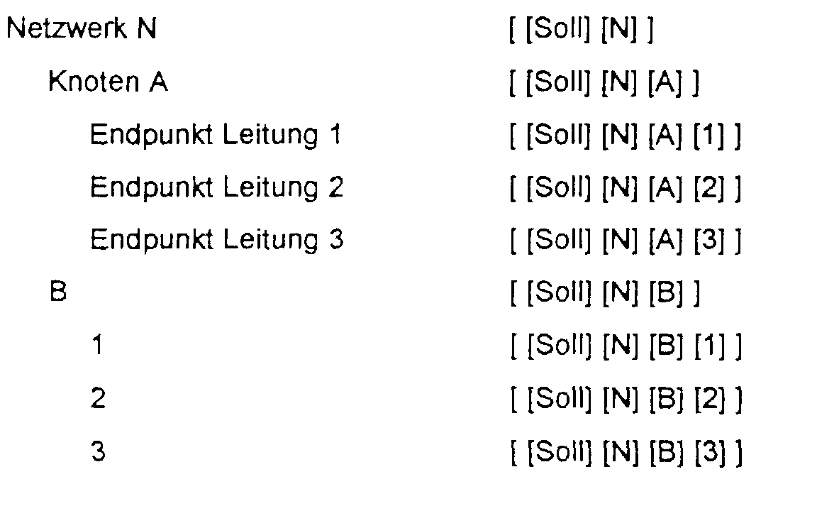
Die in Fig. 2b dargestellte Plan-Konfiguration 
Die zwei die Endpunkte der Leitung 2 repräsentierenden Objekte, die gemäss Planung zu eliminieren
ist, enthalten zusätzlich ein Attribut
Eine neue geplante Soll-Konfiguration
Bei der Abfrage des Objektes NA1 mit 〈get [ [Soll:Plan n] [N] [A] [1] 1 〉 wird hingegen keine korrespondierende
Objektadresse [ [Plan] [N] [A] [1] gefunden. Deshalb sucht die Abfrageprozedur in der
Soll-Konfiguration
Somit entsteht durch die Überlagerung der Soll-Konfiguration 

In dem anhand von Fig. 2 beschriebenen Beispiel wird eine neue geplante Soll-Konfiguration
Wie erwähnt, können mit dem beschriebenen Vorgehen zum Überlagern einer Soll-Konfiguration
mit
einer oder mehreren Plan-Konfiguration auch Fehlplanungen festgestellt werden.Es sei angenommen,
bei der Planung gemäss Fig. 2b ist statt des Objektes NB2 fälschlicherweise das Objekt NB1 als
zu löschendes Objekt eingetragen worden. Der Objektbaum gemäss Fig. 3b gibt diesen Sachverhalt
wieder. Wenn nun diese fehlerhafte Plan-Konfiguration
Claims (9)
Applications Claiming Priority (2)
| Application Number | Priority Date | Filing Date | Title |
|---|---|---|---|
| CH99/97 | 1997-01-20 | ||
| CH9997 | 1997-01-20 |
Publications (1)
| Publication Number | Publication Date |
|---|---|
| EP0854607A1 true EP0854607A1 (en) | 1998-07-22 |
Family
ID=4179235
Family Applications (1)
| Application Number | Title | Priority Date | Filing Date |
|---|---|---|---|
| EP98100787A Withdrawn EP0854607A1 (en) | 1997-01-20 | 1998-01-19 | Method for planning and configuring a communications network |
Country Status (2)
| Country | Link |
|---|---|
| EP (1) | EP0854607A1 (en) |
| BR (1) | BR9800424A (en) |
Cited By (15)
| Publication number | Priority date | Publication date | Assignee | Title |
|---|---|---|---|---|
| WO2000046960A1 (en) * | 1999-02-03 | 2000-08-10 | Gates, William, H., Iii | Audio visual architecture |
| EP1107108A1 (en) * | 1999-12-09 | 2001-06-13 | Hewlett-Packard Company, A Delaware Corporation | System and method for managing the configuration of hierarchically networked data processing devices |
| WO2001084854A1 (en) * | 2000-05-04 | 2001-11-08 | Siemens Aktiengesellschaft | Co-ordinated network-wide administration of exchanges |
| WO2001093603A1 (en) * | 2000-05-31 | 2001-12-06 | Nokia Corporation | Forming a communication network |
| WO2002065788A2 (en) * | 2001-02-12 | 2002-08-22 | Siemens Information And Communication Mobile Llc | Integrated communication server and method |
| US6745251B2 (en) | 1998-06-18 | 2004-06-01 | Nec Corporation | Communication apparatus managing inserted package mounting states and communication network management system including the same |
| DE10259391A1 (en) * | 2002-12-19 | 2004-07-08 | Phoenix Contact Gmbh & Co. Kg | Local adaptation of an intelligent unit |
| US7039943B1 (en) | 1999-02-03 | 2006-05-02 | William H. Gates, III | Audio visual architecture |
| DE102005005279A1 (en) * | 2005-02-04 | 2006-08-10 | Siemens Ag | Control entity for a communication network having a plurality of network elements |
| US7729286B2 (en) | 2005-10-07 | 2010-06-01 | Amdocs Systems Limited | Method, system and apparatus for telecommunications service management |
| US7797425B2 (en) | 2005-12-22 | 2010-09-14 | Amdocs Systems Limited | Method, system and apparatus for communications circuit design |
| US8082335B2 (en) | 2005-11-18 | 2011-12-20 | Amdocs Systems Limited | Method and system for telecommunications network planning and management |
| US8380833B2 (en) | 2006-02-20 | 2013-02-19 | Amdocs Systems Limited | Method of configuring devices in a telecommunications network |
| US8510465B2 (en) | 1999-02-03 | 2013-08-13 | Microsoft Corporation | Method and system for distributing art |
| CN103139806B (en) * | 2011-11-23 | 2018-01-12 | 中兴通讯股份有限公司 | Method and base station of the webmaster with base station configuration data decoupling |
Citations (1)
| Publication number | Priority date | Publication date | Assignee | Title |
|---|---|---|---|---|
| WO1997031451A1 (en) * | 1996-02-22 | 1997-08-28 | Mci Communications Corporation | Network management system |
-
1998
- 1998-01-19 EP EP98100787A patent/EP0854607A1/en not_active Withdrawn
- 1998-01-21 BR BR9800424-7A patent/BR9800424A/en not_active IP Right Cessation
Patent Citations (1)
| Publication number | Priority date | Publication date | Assignee | Title |
|---|---|---|---|---|
| WO1997031451A1 (en) * | 1996-02-22 | 1997-08-28 | Mci Communications Corporation | Network management system |
Non-Patent Citations (4)
| Title |
|---|
| "MANAGEMENT DES CCS#7-NETZES: EIN EVOLUTIONÄRER ANSATZ", TEC - DAS TECHNISCHE MAGAZIN VON ASCOM, no. 2, 1994, BERN, CH, pages 8 - 17, XP000500607 * |
| ANSELL J ET AL: "AN ARCHITECTURE FOR THE DESIGN OF TMN APPLICATIONS", PROCEEDINGS OF THE INTERNATIONAL CONFERENCE ON COMMUNICATIONS (ICC '93), 23 May 1993 (1993-05-23) - 26 May 1993 (1993-05-26), GENEVA, CH, pages 1635 - 1639, XP000448407 * |
| AUER S ET AL: "DAS INFORMATIONSMODELL: EIN KONZEPT FUER DAS MANAGEMENT OFFENER KOMMUNIKATIONSSYSTEME", FREQUENZ, vol. 47, no. 1/2, January 1993 (1993-01-01), BERLIN, DE, pages 49 - 57, XP000349214 * |
| SCHAPELER, G ET AL.: "MODEL BASED MAINTENANCE FOR MANS", ELECTRICAL COMMUNICATION, July 1993 (1993-07-01), PARIS, FR, pages 268 - 277, XP000394420 * |
Cited By (21)
| Publication number | Priority date | Publication date | Assignee | Title |
|---|---|---|---|---|
| US6745251B2 (en) | 1998-06-18 | 2004-06-01 | Nec Corporation | Communication apparatus managing inserted package mounting states and communication network management system including the same |
| DE19927985B4 (en) * | 1998-06-18 | 2005-11-03 | Nec Corp. | Communication device, method for physically and logically installing a packet in the communication device and storage medium |
| US9438660B2 (en) | 1999-02-03 | 2016-09-06 | William H. Gates, III | Method and system for distributing art |
| WO2000046960A1 (en) * | 1999-02-03 | 2000-08-10 | Gates, William, H., Iii | Audio visual architecture |
| US8510465B2 (en) | 1999-02-03 | 2013-08-13 | Microsoft Corporation | Method and system for distributing art |
| US8413196B2 (en) | 1999-02-03 | 2013-04-02 | Microsoft Corporation | Audio visual architecture |
| US7039943B1 (en) | 1999-02-03 | 2006-05-02 | William H. Gates, III | Audio visual architecture |
| EP1107108A1 (en) * | 1999-12-09 | 2001-06-13 | Hewlett-Packard Company, A Delaware Corporation | System and method for managing the configuration of hierarchically networked data processing devices |
| US7218726B2 (en) | 2000-05-04 | 2007-05-15 | Siemens Aktiengesellschaft | Coordinated network-wide administration of exchanges |
| WO2001084854A1 (en) * | 2000-05-04 | 2001-11-08 | Siemens Aktiengesellschaft | Co-ordinated network-wide administration of exchanges |
| WO2001093603A1 (en) * | 2000-05-31 | 2001-12-06 | Nokia Corporation | Forming a communication network |
| WO2002065788A3 (en) * | 2001-02-12 | 2002-10-24 | Opuswave Networks Inc | Integrated communication server and method |
| WO2002065788A2 (en) * | 2001-02-12 | 2002-08-22 | Siemens Information And Communication Mobile Llc | Integrated communication server and method |
| DE10259391B4 (en) * | 2002-12-19 | 2006-04-13 | Phoenix Contact Gmbh & Co. Kg | Location-specific adaptation of an intelligent unit |
| DE10259391A1 (en) * | 2002-12-19 | 2004-07-08 | Phoenix Contact Gmbh & Co. Kg | Local adaptation of an intelligent unit |
| DE102005005279A1 (en) * | 2005-02-04 | 2006-08-10 | Siemens Ag | Control entity for a communication network having a plurality of network elements |
| US7729286B2 (en) | 2005-10-07 | 2010-06-01 | Amdocs Systems Limited | Method, system and apparatus for telecommunications service management |
| US8082335B2 (en) | 2005-11-18 | 2011-12-20 | Amdocs Systems Limited | Method and system for telecommunications network planning and management |
| US7797425B2 (en) | 2005-12-22 | 2010-09-14 | Amdocs Systems Limited | Method, system and apparatus for communications circuit design |
| US8380833B2 (en) | 2006-02-20 | 2013-02-19 | Amdocs Systems Limited | Method of configuring devices in a telecommunications network |
| CN103139806B (en) * | 2011-11-23 | 2018-01-12 | 中兴通讯股份有限公司 | Method and base station of the webmaster with base station configuration data decoupling |
Also Published As
| Publication number | Publication date |
|---|---|
| BR9800424A (en) | 1999-09-08 |
Similar Documents
| Publication | Publication Date | Title |
|---|---|---|
| DE60130808T2 (en) | System and method for configuring network resources | |
| EP0854607A1 (en) | Method for planning and configuring a communications network | |
| DE60304768T2 (en) | A method and apparatus for monitoring remote devices by generating device objects for the devices to be monitored | |
| DE60316220T2 (en) | Method and device for configuring a monitoring system | |
| EP1430369B1 (en) | Dynamic access to automation resources | |
| EP1810523B1 (en) | Method and products for aligning data between a manager and an agent in a management network | |
| DE60311183T2 (en) | Method and device for supporting telemonitored devices from different manufacturers | |
| EP1152625A1 (en) | Updating of manufacturer specific harware informations at the manufacturer independent OMC-NMC interface of a mobile radio network | |
| DE19813754C2 (en) | Method and management network for configuring a radio communication network | |
| EP1206883B1 (en) | Generic alignment method in a multi-manager environment | |
| EP1547309B1 (en) | Method for updating the local management system in at least one network element of a telecommunication network | |
| DE19740718C2 (en) | Realignment procedure between an operations and maintenance center and a higher-level network management center | |
| CH686540A5 (en) | Control and/or management system for network elements | |
| WO1999022491A1 (en) | System for connecting network elements of communications installations to a telecommunications management network | |
| DE102006003391B4 (en) | Use of identification information in network management | |
| DE19720594C1 (en) | Instance number and symbolic name allocation method | |
| DE60303106T2 (en) | Command Line Interfaces Processor with dynamic update of attribute dependencies | |
| EP1035738A1 (en) | Method and network element for operating a telecommunictions network | |
| EP2002601B1 (en) | Location of unidirectional handover relationships | |
| WO2004002172A1 (en) | Method and network element for managing resources of a network element | |
| EP1703667A1 (en) | Network management using a master-replica method | |
| DE102004039214B4 (en) | Communication method in a management network for information about attribute changes | |
| DE102004039215B4 (en) | Telecommunication network management network procedure uses object model communication with attributes defined for mutual interpretation | |
| WO1999009489A2 (en) | Process and system for carrying out monitoring and management functions | |
| EP3432516A1 (en) | Network switchboards and method for automatic reconfiguration |
Legal Events
| Date | Code | Title | Description |
|---|---|---|---|
| PUAI | Public reference made under article 153(3) epc to a published international application that has entered the european phase |
Free format text: ORIGINAL CODE: 0009012 |
|
| AK | Designated contracting states |
Kind code of ref document: A1 Designated state(s): AT BE CH DE FI FR LI PT |
|
| AX | Request for extension of the european patent |
Free format text: AL;LT;LV;MK;RO;SI |
|
| 17P | Request for examination filed |
Effective date: 19990122 |
|
| AKX | Designation fees paid |
Free format text: AT BE CH DE FI FR LI PT |
|
| RBV | Designated contracting states (corrected) |
Designated state(s): AT BE CH DE FI FR LI PT |
|
| STAA | Information on the status of an ep patent application or granted ep patent |
Free format text: STATUS: THE APPLICATION IS DEEMED TO BE WITHDRAWN |
|
| 18D | Application deemed to be withdrawn |
Effective date: 20020801 |