EP0833243A2 - GUI edition aiding apparatus and method - Google Patents
GUI edition aiding apparatus and method Download PDFInfo
- Publication number
- EP0833243A2 EP0833243A2 EP97307718A EP97307718A EP0833243A2 EP 0833243 A2 EP0833243 A2 EP 0833243A2 EP 97307718 A EP97307718 A EP 97307718A EP 97307718 A EP97307718 A EP 97307718A EP 0833243 A2 EP0833243 A2 EP 0833243A2
- Authority
- EP
- European Patent Office
- Prior art keywords
- display
- display part
- gui
- parts
- display screen
- Prior art date
- Legal status (The legal status is an assumption and is not a legal conclusion. Google has not performed a legal analysis and makes no representation as to the accuracy of the status listed.)
- Granted
Links
Images


Classifications
-
- G—PHYSICS
- G06—COMPUTING; CALCULATING OR COUNTING
- G06F—ELECTRIC DIGITAL DATA PROCESSING
- G06F3/00—Input arrangements for transferring data to be processed into a form capable of being handled by the computer; Output arrangements for transferring data from processing unit to output unit, e.g. interface arrangements
- G06F3/01—Input arrangements or combined input and output arrangements for interaction between user and computer
- G06F3/048—Interaction techniques based on graphical user interfaces [GUI]
- G06F3/0481—Interaction techniques based on graphical user interfaces [GUI] based on specific properties of the displayed interaction object or a metaphor-based environment, e.g. interaction with desktop elements like windows or icons, or assisted by a cursor's changing behaviour or appearance
-
- Y—GENERAL TAGGING OF NEW TECHNOLOGICAL DEVELOPMENTS; GENERAL TAGGING OF CROSS-SECTIONAL TECHNOLOGIES SPANNING OVER SEVERAL SECTIONS OF THE IPC; TECHNICAL SUBJECTS COVERED BY FORMER USPC CROSS-REFERENCE ART COLLECTIONS [XRACs] AND DIGESTS
- Y10—TECHNICAL SUBJECTS COVERED BY FORMER USPC
- Y10S—TECHNICAL SUBJECTS COVERED BY FORMER USPC CROSS-REFERENCE ART COLLECTIONS [XRACs] AND DIGESTS
- Y10S715/00—Data processing: presentation processing of document, operator interface processing, and screen saver display processing
- Y10S715/961—Operator interface with visual structure or function dictated by intended use
- Y10S715/965—Operator interface with visual structure or function dictated by intended use for process control and configuration
- Y10S715/966—Computer process, e.g. operation of computer
- Y10S715/967—Visual or iconic programming
Definitions
- the present invention relates to a GUI (Graphical User Interface) edition aiding apparatus for aiding the edition of a GUI such as a computer application program.
- GUI Graphic User Interface
- GUI edition aiding apparatuses also referred to as GUI builders.
- buttons and lists that are referred to as GUI parts are selected from a palette and disposed in a window frame whose size can be freely changed so as to design and create a GUI. This operation is performed by a designer (user) of the GUI. With a display screen of the GUI, data that is exchanged between a computer and a user thereof is represented as a display screen of the GUI.
- a GUI is designed and created with such a GUI edition aiding apparatus, the following problem takes place.
- GUI edition aiding apparatus screens of the GUI can be easily designed and created in such a manner that the user draws pictures.
- the user since the user tends to design and create a GUI without a final image thereof, the user should modify the GUI later on. That is, it often happens to add display parts and change functions in a designing process.
- other alternatives may be added later on.
- the GUI parts are categorized as a fixed type and a non-fixed type depending on whether alternatives will be added later on. In the case of the fixed type, if alternatives are added later on, relevant screens of the GUI should be recreated.
- the user should design and create a GUI considering what and how parts are used with the final image thereof.
- the user when the user creates a GUI of which one is selected from a plurality of alternative, he or she can use representing means (parts) such as pull-down menus, exclusive buttons, and list boxes. In this case, the use of these means depends on operation types and the preference of the user(designer).
- the conventional GUI edition aiding apparatus cannot properly change a particular representing means to another representing means.
- an operation equivalent to the restructure of a GUI screen thereof should be required.
- An object of the present invention is to provide a GUI edition aiding apparatus that allows the user to design and create GUI interactive screens that are superior in operation and maintenance, a GUI edition aiding method, and a record medium recording a GUI edition aiding program thereof.
- Another object of the present invention is to provide a GUI edition aiding apparatus considering what part is a GUI part to be converted, a GUI edition aiding method thereof, and a record medium recording a GUI edition aiding program thereof.
- a further object of the present invention is to provide a GUI edition aiding apparatus considering the current position of a GUI part to be converted, a GUI edition aiding method thereof, and a record medium recording a GUI edition aiding program thereof.
- the present invention is an apparatus for creating a display screen including display parts, comprising a first selecting means for selecting a second display part into which a first display part is converted when a first command is issued for the first display part displayed on the display screen, and a first controlling means for displaying the second display part instead of the first display part on the display screen.
- the currently displayed part is converted into another display part.
- the label "OK” is converted into a text field "OK”.
- the text field "OK” is converted into a button “OK”.
- the button "OK” is converted into an option button “OK”.
- objects "a set of labels”, “a set of text fields”, “a text field with a plurality of lines”, “a set of command buttons”, “a set of check boxes”, “a set of option buttons”, “a list box”, “a combo box”, “a drop-down list box”, “a tab dialog”, and "a tree view” become conversion alternatives.
- the above applications such as a label is merely examples. The present invention is not limited to the above applications.
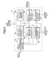
- Fig. 1 is a block diagram showing the structure of a GUI edition aiding apparatus according to a first embodiment of the present invention.
- an input portion 1 inputs character string data and bit map data used in a GUI to be created and commands and so forth corresponding to each operation condition.
- the input portion 1 is accomplished by a pointing device such as a keyboard, a mouse, and so forth.
- a displaying portion 2 displays various kinds of internal data handled by a computer to the user.
- the display portion 2 displays display parts such as windows (forms) and labels and a mouse cursor.
- the display portion 2 displays graphical data.
- the display portion 2 is accomplished by a so-called display or the like.
- the input portion 1 and the display portion 2 compose a user interface.
- a part managing portion 3 performs various managing processes for part data displayed on the display portion 2 corresponding to various types of input information received from the input portion 1. The detail of the part managing portion 3 will be described later.
- a part storing portion 4 stores character string data and bit map data received from the input portion 1 as part data.
- a converting portion 5 converts part data received from the part managing portion 3 corresponding to both a conversion rule stored in a rule storing portion 6 and conversion frequency information stored in a frequency storing portion 7.
- a learning portion 8 learns the frequency information corresponding to a predetermined learning algorithm and thereby updates the frequency information stored in the frequency information storing portion 7.
- Fig. 2 is a block diagram showing the structure of the part managing portion 3.
- an input information interpreting portion 21 interprets whether input information received from the input portion 1 is a command (or the like), character string data, or bit map data.
- the input information interpreting portion 21 outputs data or control information to each portion (that will be described later) corresponding to the interpreted result. This interpreting process is frequently performed corresponding to the operation state and input mode.
- the input information interpreting portion 21 When the input information interpreting portion 21 has interpreted that the input information received from the input portion 1 is character string data or bit map data, the input information interpreting portion 21 sends the character string data or the like to a part data registering portion 22.
- the part data registering portion 22 sends the received character string data and bit map data as part data to the part storing portion 4.
- the input information interpreting portion 21 When the input information interpreting portion 21 has interpreted that the input information received from the input portion 1 is a part selecting command, the input information interpreting portion 21 sends the input information to a part selecting portion 23.
- the part selecting portion 23 selects a relevant part (or a relevant set of parts) corresponding to the input information. In other words, the part selecting portion 23 selects a display part corresponding to both position information that composes the input information and screen information stored in a display data storing portion 24. In this case, the part selecting portion 23 may select a plurality of display parts corresponding to the input information.
- the part selecting portion 23 When the part selecting portion 23 has selected a display part, the part selecting portion 23 sends the resultant information to a part data reading portion 25.
- the part selecting portion 23 updates display data stored in the display data storing portion 23 so as to allow the user to know that the display part has been selected.
- the part data reading portion 25 reads the relevant part data from the part storing portion 4 corresponding to the information of the display part and temporarily stores the content.
- the input information interpreting portion 21 When the input information interpreting portion 21 has interpreted that the input information is a part converting command, the input information interpreting portion 21 sends the input information to a conversion commanding portion 26.
- the conversion commanding portion 26 reads the part data from the part data reading portion 25 and sends the part data to the converting portion 5.
- the part data corresponds to the display part selected by the part selecting portion 23.
- the converting portion 5 creates a list of alternatives of the selected part data (a set of parts) corresponding to both the conversion rule stored in the rule storing portion 6 and the frequency information stored in the frequency information storing portion 7 and returns the list to an alternative selecting portion 27.
- the alternative selecting portion 27 selects one from the list of alternatives and rewrites the content of the display data storing portion 24 corresponding to the selected alternative.
- the converted result is displayed on the screen of the display portion 2.
- a next alternative is selected from the top of the list of alternatives. After all the alternatives have been selected, another alternative is selected from the top of the list of alternatives. This process is accomplished in such a manner that when a converting command is successively input from the input portion 1, the input information interpreting portion 1 interprets the converting command as a next alternative interpreting command and sends the converting command to the alternative selecting portion 27.
- the input information interpreting portion 21 When the input information interpreting portion 21 has interpreted that the input information received from the input portion 1 is a part deselecting command, the input information interpreting portion 21 sends the input information to the part selecting portion 23 and the alternative selecting portion 27.
- the part selecting portion 23 updates display data of the display data storing portion 24 so as to allow the user to know that the display part has been deselected.
- the alternative selecting portion 27 sends the finally selected display part to the learning portion 8.
- a window (form) in which no part is disposed is displayed.
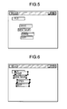
- Fig. 3 shows an example of the initial state of a window. In this example, no part is disposed. However, default parts may be defined and displayed as the initial state.
- the part data registering portion 22 creates one piece of part data composed of the character string data and preset frame data.
- the part data is stored in the part storing portion 4.
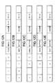
- Figs. 4A and 4B are schematic diagrams showing examples of part data stored in the part storing portion 4.
- part data is composed of a GUI part number 401, the number of elements 402, an element number 403, the number of lower elements 404, a character string 405, a part name 406, a value 407, a state 408, a position 409, a size 410, and a lower element 411.
- a character string that is received from the input portion 1 is stored with a format referred to, for examples, "label”.
- the GUI part number 401 is a unique number of the part.
- the number of elements 402 is the number of parts in the same hierarchical level of the same group. In this example, since the part data contains only one label "file", the number of elements is 1.
- the element number 403 is a unique number of each part in the same hierarchical level of the same group.
- the number of lower elements 404 is the number of parts in lower hierarchical levels in the case that a part and another part have a hierarchical relation.
- the character string 405 is a character string that each part represents.
- the part name 406 is the name of the part.
- the value 407 is the value of each part. For example, in the case of a check box, when it is checked, the value 407 is 1. When the check box is not checked, the value 407 is 0. When the part does not have a value, the value 407 is null. The value 407 depends on each part.
- the state 408 is the state of each part. In the case of a button, when it cannot be operated, the state 408 is invalid. When the part can be operated, the state 408 is valid. The state 408 depends on each part.
- the position 409 is the position of each part in the window.
- the position 409 is represented with the number of pixels.
- the size 410 is the size of each part.
- the lower element 411 is information of parts in lower hierarchical levels. When there is no lower part, the lower element 411 is null.
- Fig. 5 shows a window of which the above-described five character strings have been input.
- the above-described part data for the labels shown in Fig. 5 is stored.
- Fig. 6 shows a window in this state.
- the user clicks the mouse at the position of the label (display part) on the window of the display portion 2 a mark that represents that the label has been selected corresponding to the position information of the mouse cursor is displayed.
- the user can perform an input operation such as the drag and drop operation.
- Fig. 7 is a flow chart showing operations of the part managing portion 3 and the converting portion 5.
- the part selecting portion 23 selects part data corresponding to the input information that the user has clicked with the mouse (at step 701) and the part data reading portion 25 reads the part data (at step 702).
- the conversion commanding portion 26 reads part data from the part data reading portion 25 (at step 704) and sends the part data to the converting portion 5 (at step 705).
- the converting portion 5 converts the part data into another part data (for example a combo box) (at step 706).
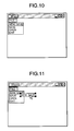
- Fig. 8 is a schematic diagram showing an example of the state that the set of labels shown in Fig. 6 is converted into a combo box.
- the user inputs a next alternative converting command from the input portion 1 (at step 707).
- the next display part is displayed (at step 708).
- Fig. 9 is a schematic diagram showing an example of the state of which a standard combo box is displayed with a next alternative converting command.
- a menu as the next alternative is displayed.
- Fig. 10 is a schematic diagram showing an example of the state of which the menu is displayed with the next alternative converting command.
- the user repeats the input of the next alternative converting command until a desired display part is displayed.
- the desired display part is displayed, the user confirms it with the input portion 1 (at step 709). As a result, the process is completed.
- Fig. 11 is a schematic diagram showing an example of the state of which the order of the display parts is changed.
- part data is stored in the part data storing portion 4 as shown in Figs. 12A to 12E.
- Fig. 13 is a flow chart showing the converting process of the GUI edition aiding apparatus according to the embodiment.
- the converting portion 5 When obtaining part data, the converting portion 5 creates a list of available parts (at step 1301).
- the converting portion 5 creates the list in a predetermined format.
- the format In the case that one part has been selected, the format is defined in such a manner that "a label”, “a text”, “a button”, and “a check button” can be selected.
- the form In the case that a plurality of parts have been selected, the form is defined in such a manner that "a set of labels”, “a set of text files”, “a text field with a plurality of lines”, “a set of command buttons”, “a set of check boxes”, “a set of option buttons”, “a list box", “a combo box”, “a drop-down list box", “a tab dialog", and "a tree view” can be selected.
- the converting portion 5 determines whether or not there is a rule that matches the current state corresponding to a rule stored in the rule storing portion 6 (at step 1302).
- Examples of rules stored in the rule storing portion 6 are:
- the flow advances to step 1303.
- the converting portion 5 changes the value of the priority of the list of available parts created at step 1301. Thereafter, the flow returns to step 1302.
- the converting portion 5 determines whether or not there is a matched rule.
- the converting portion 5 reads the frequency information from the frequency information storing portion 7 and changes the value of the priority of the list of available parts created at step 1301 corresponding to the frequency information (at step 1304). Thereafter, the flow advances to step 1305.
- the converting portion 5 sorts the list of available parts created at step 1301 corresponding to the priority. The sorted result is sent to the alternative selecting portion 27 of the part managing portion 3 (at step 1306). Thus, the selected alternative is displayed.
- the alternative selecting portion 27 sends the information of the confirmed part data to the learning portion 8.
- the learning portion 8 adds "1" to the current frequency information of the display part corresponding to the information and updates the frequency information of the frequency information storing portion 7 as new frequency information.
- the learning portion 8 can use event base inference, functional learn and neural network and so on, as well as frequency information. In this case, the learning portion 8 stores the structure of a confirmed display part as an event. When there is a similar structure as a past event, the learning portion 8 corrects the past event with the event base inference and creates an alternative.
- GUI part to be converted When a GUI part is converted, a new part is created or a GUI part that has been created is modified. In the latter case, since the GUI part to be converted may have some meaning, an example of which a part is converted with the type of the current part will be described.
- Fig. 14 is a block diagram showing the structure of a GUI edition aiding apparatus according to the second embodiment of the present invention.
- a part identifying portion 141 identifies the type of a part to be converted.
- Fig. 15 is a flow chart showing the operation of the part identifying portion 11.
- a conversion commanding portion 26 sends a converting command to a converting portion 5 and informs the part identifying portion 141 of a GUI part to be converted (see Figs. 4A and 4B).
- the part identifying portion 141 identifies the type of the part with the data received from the conversion commanding portion 26.
- the part identifying portion 141 extracts the following two GUI parts and identifies the types thereof.
- each part is denoted as follows. part type[name] (structural element, 7), ...
- the part type represents the type of the current part (part name). Examples of the part type are a label, a button, an option, a combo, a frame, a menu, and so forth.
- label["age”:”] () represents a label that has a character string "age:”. Since a label does not have a structural element, it is represented by blank parentheses. When one part has a plurality of character strings, they are delimited with commas.
- the part has the part type and label name instead of a character string.
- the format thereof is as follows.
- the part identifying portion 141 when the part identifying portion 141 has obtained information of a GUI part, the part identifying portion 141 sends the information of the GUI part to the converting portion 5.
- the converting portion 5 converts the current GUI part into another GUI part corresponding to the rule stored in the rule storing portion 6.
- the left side (the left side of the arrow) represents a satisfying condition.
- the part is converted into a set of parts.
- brackets [] represents the intensity (weight) of each rule.
- a variable with an asterisk "*" represents a plurality of items.
- the conformance of each rule is given as follows.
- the conformance of each rule represents the number of conditions that are satisfied.
- the priority of conversion alternatives is in the order of the rule 1, rule 4, rule 3, and rule 2.
- a proper GUI part is more effectively designated as a selection alternative corresponding to the screen on which the GUI part is disposed or to the position in the window.
- Fig. 18 is a block diagram showing the structure of a GUI edition aiding apparatus according to the third embodiment of the present invention.
- a position calculating portion 181 calculates the position of a current GUI part on the screen.
- the position of each GUI part on the screen is represented with both the ratio between the center position of each GUI part and the upper edge of the screen and the ratio between the center position of each GUI part and the left edge of the screen.
- Fig. 19 is a flow chart showing the operation of the GUI edition aiding apparatus according to the third embodiment of the present invention.
- a conversion commanding portion 26 sends a converting command to a converting portion 5 (at step 1902) and informs a position detecting portion 181 of a GUI part to be converted (at step 1903).
- the position detecting portion 181 calculates the position of the GUI part (at step 1904).
- the values of a button 1 (12.5 %, 12.5 %), a button 2 (37.5 %, 87.5 %), and a button (65.5 %, 87.5 %) are output to the converting portion 5 (at step 1905).
- Absolute coordinates on a display screen can be used instead of relative coordinates thereon.
- the converting portion 5 converts the GUI part into a relevant GUI part corresponding to the output data of the converting portion 5 (at step 1906).
- the button 1 since the button 1 is disposed at an upper position of the screen, it is converted into an upper menu.
- the button 2 since the button 2 is disposed at a lower position of the screen, the button 2 is converted into a lower menu.
- the values in percent given as arguments of the label are conditions compared with the current position of a GUI part. In other words, when the upper/lower position of the conversion alternative label is larger than 50 % (disposed at the lower half of the window) and the left/right position is smaller than 50 % (disposed at the left half of the window), the conditions of the rule are satisfied.
- a more user-friendly GUI can be structured.
- the part identifying portion 141 is disposed in addition to the position detecting portion 181.
- the position detecting portion 181 may be disposed. In this case, the rules 1 to 4 are not required.
- GUI parts In a window shown in Fig. 21A, when there are many "buttons", it is troublesome for the user to arrange them with what GUI part as a title thereof.
- the order of GUI parts is designated corresponding to the positions thereof on the window.
- GUI parts "age:”, “age 20 below”, “age 20 to age 30”, “age 30 to age 40”, “age 40 to age 50”, “age 50 to age 60”, and “age 60 over” are dispersed in a window shown in Fig. 21A.
- Fig. 22 is a block diagram showing the structure of the GUI edition aiding apparatus according to the fourth embodiment of the present invention.
- an order calculating portion 221 shown in Fig. 22 obtains the order of GUI parts to be converted.
- the order calculating portion 221 designates the order of the GUI parts downwardly.
- the difference between the height of a particular GUI part and the height of another GUI part is N or less (where N is constant)
- the order calculating portion 221 designates the order of the GUI parts so that GUI parts on the left have precedence over GUI parts on the right.
- the order calculating portion 221 designates the order of the GUI parts rightwardly.
- the order calculating portion 221 designates the order of the GUI parts so that upper GUI parts have precedence over lower GUI parts.
- Inverse number of parts size being arranged can be used as M and N.
- the order calculating portion 221 designates the order of the GUI parts so that the upper GUI parts have precedence over lower GUI parts.
- Fig. 23 is a flow chart for explaining the operation of the order determining portion 221.
- the order determining portion 221 determines whether the rectangular area that inscribes all the GAI parts is a portrait rectangle or a landscape rectangle (at step 2301).
- the order determining portion 221 sets a vertical precedence flag (at step 2302).
- the order determining portion 221 sets a horizontal precedence flag (at step 2303). In this case, the GUI parts are selected from the direction represented by the flags.
- the order determining portion 221 performs an initializing process for a loop process (at step 2304). The order determining portion 221 repeats the following process until the value of a variable j exceeds the number of GUI parts (at step 2305).
- the order determining portion 221 selects i-th and j-th GUI parts corresponding to the direction precedence flags (at step 2306). Next, the order determining portion 221 determines whether or not the difference between the positions of the two GUI parts is within the constant N (at step 2307). In the case of the vertical precedence, the difference between the positions of two GUI parts is the difference between the horizontal center axes of two GUI parts. Thus, the difference is the height. In the case of the horizontal precedence, the difference between the positions of two GUI parts is the difference between vertical center axes of two GUI parts.
- the order determining portion 221 determines whether or not the i-th GUI part is disposed on the left of the j-th GUI part (or whether or not the i-th GUI part is disposed above the j-th GUI part in the case of the horizontal precedence) (at step 2308).
- the i-th GUI part is disposed on the left of (or above) the j-th GUI part, assuming that the order of the i-th GUI part is designated as p, the order of the j-th GUI part is designated as (p - 1) (at step 2309).
- the flow advances to step 2309.
- the order determining portion 221 substitutes the priority of the i-th GUI part with the priority of the j-th GUI part. Thereafter, the order determining portion 221 shifts a relevant GUI part by one and thereby increments the variable by 1 (at step 2311). The order determining portion 221 repeats the above-described process until the above-described conditions are satisfied.
- the order designating method of GUI parts is not limited to the above-described method as long as the order thereof is uniquely designated.
- Examples of the order designating methods are order of selection of parts, left precedence, upper precedence, upper precedence and left precedence for the first L GUI parts.
- a plurality of GUI parts are grouped and converted so as to optimally dispose the GUI parts.
- GUI parts are disposed in a window as shown in Fig. 24A, when they are normally converted, they are displayed as shown in Fig. 24B.
- the GUI parts are converted as shown in Fig. 24C.
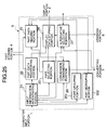
- Fig. 25 is a block diagram showing the structure of a GUI edition aiding apparatus according to the fifth embodiment of the present invention.
- a part grouping portion 251 when a part grouping portion 251 receives a grouping command from the input portion 1, the part grouping portion 251 groups a particular set of GUI parts corresponding to a predetermined rule.
- a part degrouping portion 252 degroups the set of GUI parts that have been grouped by the part grouping portion 251.
- Fig. 26 is a flow chart showing a grouping process of the part grouping portion 251.
- the part grouping portion 251 correlates every two of all GUI parts disposed (at step 2601). Next, the part grouping portion 251 obtains the straight distance between these two GUI parts (at step 2602). This distance is the straight distance between the center points of these GUI parts.
- Fig. 27A is a schematic diagram for calculating the straight distance between every two GUI parts.
- Fig. 27A shows the state that the center points of every two GUI parts in the window shown in Fig. 24A are connected with a straight line.
- the part grouping portion 251 selects the longest line from the correlated lines (at step 2603).
- the part grouping portion 251 decorrelates the GUI parts corresponding to the selected line (at step 2604). Thereafter, the part grouping portion 251 successively traces the lines for the individual GUI parts in a predetermined order (at step 2605).
- the part grouping portion 251 determines whether or not all the GUI parts have been connected with the lines (namely the GUI parts have been separated) (at step 2606). In reality, the part grouping portion 251 traces GUI parts "2" from a GUI part "1" (assuming that the GUI part "nationality" is "1").
- the part grouping portion 251 can trace a GUI part "2" from the GUI part "1" from the GUI part "1"
- the part grouping portion 251 marks "1" in an internal table (for example, an array variable).
- the part grouping portion 251 can determine whether or not each GUI part has been separated (see Fig. 27B).
- the method for calculating the distance between each GUI part is not limited to the above-described method. In other words, the distance between edge positions of GUI parts may be used.
- the grouping method is not limited to the above-described method. In other words, after GUI parts to be grouped are selected with the mouse, a grouping command may be input.
- a group number calculating portion detects the number of groups.
- Fig. 28 is a block diagram showing the structure of a GUI edition aiding apparatus according to the sixth embodiment of the present invention.
- a part identifying portion 141 identifies the type of a selected GUI part and sends the resultant data to a group number counting portion 281.
- the group number counting portion 281 counts the number of GUI parts of each group and treats a group with the smallest number of GUI parts as an alternative of the number of groups and sends the resultant data to a grouping portion 251.
- the grouping portion 251 separates the GUI parts until the commanded number of groups is obtained.
- the grouping portion 251 separates the GUI parts until the commanded number of groups is obtained.
- GUI parts can be easily substituted with other GUI parts when they have similar meaning.
- a more user-friendly GUI can be easily created.
Abstract
Description
label["age":"] ()
combo[] ("
part type[name] (structural element, ...), ...
menu["file"]("open","close",[menu]("reread","rewrite")
part type (character string), part type (character string, ...), ... -> part name (character string), part name (character string, ...)
label[""]() -> button["cancel"]()
represents that a label "cancel" is converted into a button "cancel". Instead of a character string, a variable name can be used.
label[$a+"button"] (),label[$b] () ->
button[$a]().button[$b]()
frame[$a](option[$b*]())
Rule 5[20]:label[$a](>50%,<50%)() -> button[$a]()
button[$a](),button[$b*]() -> label[$a](),combo[$b*]()
when the rule is satisfied, a converted screen as shown in Fig. 16 is obtained.
Claims (17)
- An apparatus for creating a display screen including display parts, comprising:first selecting means for selecting a second display part into which a first display part is converted when a first command is issued for the first display part displayed on the display screen; andfirst controlling means for displaying the second display part instead of the first display part on the display screen.
- The apparatus as set forth in claim 1, further comprising:second selecting means for selecting a third display part into which the second display part is converted corresponding to a second command issued to the second display part displayed on the display screen; andsecond controlling means for displaying the third display part instead of the second display part on the display screen.
- The apparatus as set forth in claim 1,
wherein said first selecting means selects the second display part into which the first display part is converted corresponding to a predetermined rule. - The apparatus as set forth in claim 2,
wherein said second selecting means selects the third display part into which the second display part is converted corresponding to a predetermined rule. - The apparatus as set forth in claim 3,
wherein the predetermined rule includes structural information of the display parts displayed on the display screen. - The apparatus as set forth in claim 4,
wherein the predetermined rule includes structural information of the display parts displayed on the display screen. - The apparatus as set forth in claim 4, further comprising:confirming means for confirming the second display part as a display part,wherein the predetermined rule includes as frequency information the number of times of which the second display part is confirmed as a display part.
- The apparatus as set forth in claim 7, further comprising:
learning means for updating frequency information corresponding to a predetermined learning rule when the second display part is confirmed as a display part. - The apparatus as set forth in claim 1, further comprising:storing means for storing type information of the first display part; andweight storing means for storing the weight of each of a plurality of rules that represent the hierarchical relation of a plurality of pieces of the type information,wherein said first selecting means selects the second display part into which the first display part is converted corresponding to the type information and the weight information.
- The apparatus as set forth in claim 1, further comprising:calculating means for calculating the display position of the first display part on the display screen,wherein said first selecting means selects the second display part into which the first display part is converted corresponding to the calculated display position.
- The apparatus as set forth in claim 1, further comprising:calculating means for calculating the display positions of a plurality of first display parts on the display screen; anddetermining means for determining the display positions of second display parts on the display screen corresponding to the calculated display positions.
- The apparatus as set forth in claim 1, further comprising:grouping means for grouping a plurality of first display parts; anddetermining means for determining the display positions of second display parts on the display screen, the display positions being grouped corresponding to a predetermined rule.
- The apparatus as set forth in claim 12, further comprising:calculating means for calculating the number of groups corresponding to the types of the first display parts,wherein said grouping means groups the first display parts corresponding to the calculated number of groups.
- A method for creating a display screen including display parts, comprising the steps of:selecting a second display part into which a first display part is converted when a first command is issued for the first display part displayed on the display screen; anddisplaying the second display part instead of the first display part on the display screen.
- The method as set forth in claim 14, further comprising the steps of:selecting a third display part into which the second display part is converted corresponding to a second command issued to the second display part displayed on the display screen; anddisplaying the third display part instead of the second display part on the display screen.
- A record medium recording a program that causes a display screen including display parts to be created, the program comprising the functions of:selecting a second display part into which a first display part is converted when a first command is issued for the first display part displayed on the display screen; anddisplaying the second display part instead of the first display part on the display screen.
- The record medium as set forth in claim 16, the program further comprising the functions of:selecting a third display part into which the second display part is converted corresponding to a second command issued to the second display part displayed on the display screen; anddisplaying the third display part instead of the second display part on the display screen.
Applications Claiming Priority (6)
| Application Number | Priority Date | Filing Date | Title |
|---|---|---|---|
| JP25953596 | 1996-09-30 | ||
| JP25953596 | 1996-09-30 | ||
| JP259535/96 | 1996-09-30 | ||
| JP21456097 | 1997-08-08 | ||
| JP214560/97 | 1997-08-08 | ||
| JP21456097 | 1997-08-08 |
Publications (3)
| Publication Number | Publication Date |
|---|---|
| EP0833243A2 true EP0833243A2 (en) | 1998-04-01 |
| EP0833243A3 EP0833243A3 (en) | 1999-11-17 |
| EP0833243B1 EP0833243B1 (en) | 2003-05-02 |
Family
ID=26520386
Family Applications (1)
| Application Number | Title | Priority Date | Filing Date |
|---|---|---|---|
| EP97307718A Expired - Lifetime EP0833243B1 (en) | 1996-09-30 | 1997-09-30 | GUI edition aiding apparatus and method |
Country Status (3)
| Country | Link |
|---|---|
| US (1) | US5973686A (en) |
| EP (1) | EP0833243B1 (en) |
| DE (1) | DE69721424T2 (en) |
Cited By (1)
| Publication number | Priority date | Publication date | Assignee | Title |
|---|---|---|---|---|
| EP1662382A2 (en) | 2004-11-26 | 2006-05-31 | Canon Kabushiki Kaisha | Method for constructing user interface |
Families Citing this family (31)
| Publication number | Priority date | Publication date | Assignee | Title |
|---|---|---|---|---|
| US6263346B1 (en) * | 1998-07-17 | 2001-07-17 | International Business Machines Corporation | Network with storage of all client computer programs in server computer having customized client graphical user interfaces with maximum sharing of stored portions of interfaces common to a plurality of clients |
| US5966123A (en) * | 1998-09-30 | 1999-10-12 | Harris Corporation | Meta model editor controlling topic display application |
| US8121891B2 (en) * | 1998-11-12 | 2012-02-21 | Accenture Global Services Gmbh | Personalized product report |
| US7076504B1 (en) | 1998-11-19 | 2006-07-11 | Accenture Llp | Sharing a centralized profile |
| US6195651B1 (en) | 1998-11-19 | 2001-02-27 | Andersen Consulting Properties Bv | System, method and article of manufacture for a tuned user application experience |
| AU2001227911A1 (en) * | 2000-03-13 | 2001-09-24 | Stagecast Software, Inc. | Apparatus for recompiling instruction produced from graphical based system |
| US7779359B2 (en) * | 2000-08-08 | 2010-08-17 | The United States Of America As Represented By The Secretary Of The Army | Multifunction display design tool |
| US7376905B2 (en) * | 2002-12-20 | 2008-05-20 | International Business Machines Corporation | Method, system, and computer program product for user-specified GUI object distribution |
| US20040165012A1 (en) * | 2003-02-20 | 2004-08-26 | International Business Machines Corp. | Cascading menu with selectable offset |
| US7769794B2 (en) | 2003-03-24 | 2010-08-03 | Microsoft Corporation | User interface for a file system shell |
| US7823077B2 (en) | 2003-03-24 | 2010-10-26 | Microsoft Corporation | System and method for user modification of metadata in a shell browser |
| US7240292B2 (en) | 2003-04-17 | 2007-07-03 | Microsoft Corporation | Virtual address bar user interface control |
| US7627552B2 (en) | 2003-03-27 | 2009-12-01 | Microsoft Corporation | System and method for filtering and organizing items based on common elements |
| US7421438B2 (en) | 2004-04-29 | 2008-09-02 | Microsoft Corporation | Metadata editing control |
| US7712034B2 (en) | 2003-03-24 | 2010-05-04 | Microsoft Corporation | System and method for shell browser |
| US7650575B2 (en) | 2003-03-27 | 2010-01-19 | Microsoft Corporation | Rich drag drop user interface |
| US7925682B2 (en) | 2003-03-27 | 2011-04-12 | Microsoft Corporation | System and method utilizing virtual folders |
| US8230366B2 (en) * | 2003-10-23 | 2012-07-24 | Apple Inc. | Dynamically changing cursor for user interface |
| US8024335B2 (en) | 2004-05-03 | 2011-09-20 | Microsoft Corporation | System and method for dynamically generating a selectable search extension |
| US7694236B2 (en) | 2004-04-23 | 2010-04-06 | Microsoft Corporation | Stack icons representing multiple objects |
| US7657846B2 (en) | 2004-04-23 | 2010-02-02 | Microsoft Corporation | System and method for displaying stack icons |
| US8707209B2 (en) | 2004-04-29 | 2014-04-22 | Microsoft Corporation | Save preview representation of files being created |
| US7523440B2 (en) * | 2004-11-16 | 2009-04-21 | The Mathworks, Inc. | Dynamic generation of formatted user interfaces in software environments |
| US7614016B2 (en) | 2005-04-21 | 2009-11-03 | Microsoft Corporation | Multiple roots in navigation pane |
| US8195646B2 (en) | 2005-04-22 | 2012-06-05 | Microsoft Corporation | Systems, methods, and user interfaces for storing, searching, navigating, and retrieving electronic information |
| US7665028B2 (en) | 2005-07-13 | 2010-02-16 | Microsoft Corporation | Rich drag drop user interface |
| CN100517205C (en) * | 2006-04-21 | 2009-07-22 | 邱波 | Synchronous multi-dimensional speed-increasing space-saving system display method for IT field |
| JP4737270B2 (en) * | 2008-10-31 | 2011-07-27 | 富士ゼロックス株式会社 | Image processing apparatus and program |
| US9258458B2 (en) * | 2009-02-24 | 2016-02-09 | Hewlett-Packard Development Company, L.P. | Displaying an image with an available effect applied |
| USD686637S1 (en) * | 2009-03-11 | 2013-07-23 | Apple Inc. | Display screen or portion thereof with icon |
| SG188995A1 (en) * | 2010-10-14 | 2013-05-31 | Peng Ooi Goh | Method and system for modelling or transforming a process |
Citations (4)
| Publication number | Priority date | Publication date | Assignee | Title |
|---|---|---|---|---|
| US5335320A (en) * | 1990-10-22 | 1994-08-02 | Fuji Xerox Co., Ltd. | Graphical user interface editing system |
| US5347627A (en) * | 1992-04-07 | 1994-09-13 | International Business Machines Corporation | Graphical user interface including dynamic sizing and spacing |
| WO1996015493A1 (en) * | 1994-11-14 | 1996-05-23 | Taligent, Inc. | Object-oriented operating system |
| US5555370A (en) * | 1993-12-28 | 1996-09-10 | International Business Machines Corporation | Method and system for creating complex objects for use in application development |
Family Cites Families (6)
| Publication number | Priority date | Publication date | Assignee | Title |
|---|---|---|---|---|
| US5347629A (en) * | 1992-04-07 | 1994-09-13 | International Business Machines Corporation | Graphical user interface including updating of multiple panels using what you see is what you get (WYSIWYG) editor |
| JP2522898B2 (en) * | 1992-09-08 | 1996-08-07 | インターナショナル・ビジネス・マシーンズ・コーポレイション | Dynamic customization method and graphic resource editor |
| US5490245A (en) * | 1993-08-12 | 1996-02-06 | Ast Research, Inc. | Component-based icon construction and customization system |
| US5530796A (en) * | 1994-09-30 | 1996-06-25 | International Business Machines Corporation | Menu bar editor |
| US5721847A (en) * | 1994-10-21 | 1998-02-24 | Microsoft Corporation | Method and system for linking controls with cells of a spreadsheet |
| US5764226A (en) * | 1995-12-29 | 1998-06-09 | International Business Machine Corp. | Reusable and modifiable data entry interface part |
-
1997
- 1997-09-30 US US08/940,971 patent/US5973686A/en not_active Expired - Fee Related
- 1997-09-30 DE DE69721424T patent/DE69721424T2/en not_active Expired - Fee Related
- 1997-09-30 EP EP97307718A patent/EP0833243B1/en not_active Expired - Lifetime
Patent Citations (4)
| Publication number | Priority date | Publication date | Assignee | Title |
|---|---|---|---|---|
| US5335320A (en) * | 1990-10-22 | 1994-08-02 | Fuji Xerox Co., Ltd. | Graphical user interface editing system |
| US5347627A (en) * | 1992-04-07 | 1994-09-13 | International Business Machines Corporation | Graphical user interface including dynamic sizing and spacing |
| US5555370A (en) * | 1993-12-28 | 1996-09-10 | International Business Machines Corporation | Method and system for creating complex objects for use in application development |
| WO1996015493A1 (en) * | 1994-11-14 | 1996-05-23 | Taligent, Inc. | Object-oriented operating system |
Cited By (2)
| Publication number | Priority date | Publication date | Assignee | Title |
|---|---|---|---|---|
| EP1662382A2 (en) | 2004-11-26 | 2006-05-31 | Canon Kabushiki Kaisha | Method for constructing user interface |
| EP1662382A3 (en) * | 2004-11-26 | 2007-10-31 | Canon Kabushiki Kaisha | Method for constructing user interface |
Also Published As
| Publication number | Publication date |
|---|---|
| DE69721424D1 (en) | 2003-06-05 |
| US5973686A (en) | 1999-10-26 |
| DE69721424T2 (en) | 2004-05-06 |
| EP0833243A3 (en) | 1999-11-17 |
| EP0833243B1 (en) | 2003-05-02 |
Similar Documents
| Publication | Publication Date | Title |
|---|---|---|
| US5973686A (en) | GUI edition aiding apparatus, GUI edition aiding method, and record medium recording GUI edition aiding program | |
| JP4970714B2 (en) | Extract metadata from a specified document area | |
| JP4356847B2 (en) | Field definition information generation method, line and field definition information generation device | |
| US5708764A (en) | Hotlinks between an annotation window and graphics window for interactive 3D graphics | |
| US5161211A (en) | Method and system of specification processing | |
| US5590265A (en) | System which can display multiwindows and its window dosplay method | |
| US5550967A (en) | Method and apparatus for generating and displaying visual cues on a graphic user interface | |
| US7840524B2 (en) | Method and apparatus for indexing, searching and displaying data | |
| US5929858A (en) | Device for aiding analysis of infeasible solution and unbounded solution | |
| US6466694B2 (en) | Document image processing device and method thereof | |
| US7730397B2 (en) | System and method for rapid presentation of structured digital content items | |
| EP1661064B1 (en) | Document scanner | |
| JP4294348B2 (en) | Display system | |
| US7996761B2 (en) | Table format data processing method and table format data processing | |
| US20080104020A1 (en) | Handwritten Query Builder | |
| EP0764898B1 (en) | Page turning apparatus for use with computer system | |
| CA2309050A1 (en) | Publication file conversion and display | |
| US5774713A (en) | File creating method for constructing system environment, system environment constructing method and command start system | |
| US20100185967A1 (en) | Information Processing Device, and File Managing Method | |
| JP3588540B2 (en) | GUI creation support device, GUI creation support method, and recording medium recording GUI creation support program | |
| JPH0524551B2 (en) | ||
| JP2003241964A (en) | Software maintenance data generation device and generation program | |
| JP3185931B2 (en) | Hypertext editing device | |
| JPH0887509A (en) | Information display method | |
| JPH09297770A (en) | Hierarchical structure visualizing device |
Legal Events
| Date | Code | Title | Description |
|---|---|---|---|
| PUAI | Public reference made under article 153(3) epc to a published international application that has entered the european phase |
Free format text: ORIGINAL CODE: 0009012 |
|
| 17P | Request for examination filed |
Effective date: 19971014 |
|
| AK | Designated contracting states |
Kind code of ref document: A2 Designated state(s): DE FR GB |
|
| PUAL | Search report despatched |
Free format text: ORIGINAL CODE: 0009013 |
|
| AK | Designated contracting states |
Kind code of ref document: A3 Designated state(s): AT BE CH DE DK ES FI FR GB GR IE IT LI LU MC NL PT SE |
|
| RIC1 | Information provided on ipc code assigned before grant |
Free format text: 6G 06F 3/033 A, 6G 06F 9/44 B |
|
| AKX | Designation fees paid |
Free format text: DE FR GB |
|
| 17Q | First examination report despatched |
Effective date: 20020219 |
|
| GRAH | Despatch of communication of intention to grant a patent |
Free format text: ORIGINAL CODE: EPIDOS IGRA |
|
| GRAH | Despatch of communication of intention to grant a patent |
Free format text: ORIGINAL CODE: EPIDOS IGRA |
|
| GRAA | (expected) grant |
Free format text: ORIGINAL CODE: 0009210 |
|
| AK | Designated contracting states |
Designated state(s): DE FR GB |
|
| REG | Reference to a national code |
Ref country code: GB Ref legal event code: FG4D |
|
| REF | Corresponds to: |
Ref document number: 69721424 Country of ref document: DE Date of ref document: 20030605 Kind code of ref document: P |
|
| ET | Fr: translation filed | ||
| PLBE | No opposition filed within time limit |
Free format text: ORIGINAL CODE: 0009261 |
|
| STAA | Information on the status of an ep patent application or granted ep patent |
Free format text: STATUS: NO OPPOSITION FILED WITHIN TIME LIMIT |
|
| 26N | No opposition filed |
Effective date: 20040203 |
|
| PGFP | Annual fee paid to national office [announced via postgrant information from national office to epo] |
Ref country code: DE Payment date: 20070927 Year of fee payment: 11 |
|
| PGFP | Annual fee paid to national office [announced via postgrant information from national office to epo] |
Ref country code: GB Payment date: 20070926 Year of fee payment: 11 |
|
| PGFP | Annual fee paid to national office [announced via postgrant information from national office to epo] |
Ref country code: FR Payment date: 20070914 Year of fee payment: 11 |
|
| GBPC | Gb: european patent ceased through non-payment of renewal fee |
Effective date: 20080930 |
|
| REG | Reference to a national code |
Ref country code: FR Ref legal event code: ST Effective date: 20090529 |
|
| PG25 | Lapsed in a contracting state [announced via postgrant information from national office to epo] |
Ref country code: DE Free format text: LAPSE BECAUSE OF NON-PAYMENT OF DUE FEES Effective date: 20090401 |
|
| PG25 | Lapsed in a contracting state [announced via postgrant information from national office to epo] |
Ref country code: FR Free format text: LAPSE BECAUSE OF NON-PAYMENT OF DUE FEES Effective date: 20080930 |
|
| PG25 | Lapsed in a contracting state [announced via postgrant information from national office to epo] |
Ref country code: GB Free format text: LAPSE BECAUSE OF NON-PAYMENT OF DUE FEES Effective date: 20080930 |