EP0823712A1 - Method and system for determining nuclear reactor core control blade positioning - Google Patents
Method and system for determining nuclear reactor core control blade positioning Download PDFInfo
- Publication number
- EP0823712A1 EP0823712A1 EP97306079A EP97306079A EP0823712A1 EP 0823712 A1 EP0823712 A1 EP 0823712A1 EP 97306079 A EP97306079 A EP 97306079A EP 97306079 A EP97306079 A EP 97306079A EP 0823712 A1 EP0823712 A1 EP 0823712A1
- Authority
- EP
- European Patent Office
- Prior art keywords
- control blade
- population
- arrangement
- blade
- new
- Prior art date
- Legal status (The legal status is an assumption and is not a legal conclusion. Google has not performed a legal analysis and makes no representation as to the accuracy of the status listed.)
- Granted
Links
Images

Classifications
-
- G—PHYSICS
- G21—NUCLEAR PHYSICS; NUCLEAR ENGINEERING
- G21D—NUCLEAR POWER PLANT
- G21D3/00—Control of nuclear power plant
- G21D3/001—Computer implemented control
-
- G—PHYSICS
- G21—NUCLEAR PHYSICS; NUCLEAR ENGINEERING
- G21C—NUCLEAR REACTORS
- G21C7/00—Control of nuclear reaction
- G21C7/06—Control of nuclear reaction by application of neutron-absorbing material, i.e. material with absorption cross-section very much in excess of reflection cross-section
- G21C7/08—Control of nuclear reaction by application of neutron-absorbing material, i.e. material with absorption cross-section very much in excess of reflection cross-section by displacement of solid control elements, e.g. control rods
-
- G—PHYSICS
- G21—NUCLEAR PHYSICS; NUCLEAR ENGINEERING
- G21C—NUCLEAR REACTORS
- G21C7/00—Control of nuclear reaction
- G21C7/36—Control circuits
-
- Y—GENERAL TAGGING OF NEW TECHNOLOGICAL DEVELOPMENTS; GENERAL TAGGING OF CROSS-SECTIONAL TECHNOLOGIES SPANNING OVER SEVERAL SECTIONS OF THE IPC; TECHNICAL SUBJECTS COVERED BY FORMER USPC CROSS-REFERENCE ART COLLECTIONS [XRACs] AND DIGESTS
- Y02—TECHNOLOGIES OR APPLICATIONS FOR MITIGATION OR ADAPTATION AGAINST CLIMATE CHANGE
- Y02E—REDUCTION OF GREENHOUSE GAS [GHG] EMISSIONS, RELATED TO ENERGY GENERATION, TRANSMISSION OR DISTRIBUTION
- Y02E30/00—Energy generation of nuclear origin
- Y02E30/30—Nuclear fission reactors
Definitions
- This invention relates generally to nuclear reactors and more particularly, to identifying optimum control blade positioning in a nuclear reactor core.
- a nuclear reactor core includes individual fuel assemblies that have different characteristics that affect the strategy for operation of the core.
- a nuclear reactor core has many, e.g., several hundred, individual fuel bundles that have different characteristics.
- Such bundles preferably are arranged within the reactor core so that the interaction between the fuel bundles satisfies all regulatory and reactor design constraints, including governmental and customer specified constraints.
- the core loading arrangement determines the cycle energy, i.e., the amount of energy that the reactor core generates before the core needs to be refreshed with new fuel elements, the core loading arrangement preferably optimizes the core cycle energy.
- the reactor core is periodically refueled with fresh fuel assemblies.
- the higher reactivity bundles generally are positioned at an inner core location.
- higher reactivity bundles generally are positioned at an outer core location.
- the most depleted fuel bundles, i.e., the bundles with the least remaining energy content, are removed from the reactor.
- the interval between refuelings is referred to as a cycle of operation.
- the excess reactivity which defines the energy capability of the core, is controlled in two ways. Specifically, a burnable poison, e.g., gadolinia, is incorporated in the fresh fuel.
- the quantity of initial burnable poison is determined by design constraints typically set by the utility and by the NRC. The burnable poison controls most, but not all, of the excess reactivity.
- Control blades also control the excess reactivity.
- the reactor core contains control rods which assure safe shutdown and provide the primary mechanism for controlling the maximum power peaking factor.
- the total number of control blades available varies with core size and geometry, and is typically between 50 and 150.
- the position of the control blades, i.e., fully inserted, fully withdrawn, or somewhere in between, is based on the need to control the excess reactivity and to meet other operational constraints, such as the maximum core power peaking factor.
- For each control blade there are twenty five possible positions, for example. Considering symmetry and other requirements that reduce the number of control blades that are available for application at any given time, there are more than six million possible combinations of control blade positions for even the simplest case. Of these possible configurations, only a small fraction satisfy all applicable design constraints, and of these, only a small fraction are economical.
- control blade positioning also influences the cycle energy that any given fuel loading can achieve.
- the control blade positioning problem therefore may be represented as an optimization with constraints problem.
- control blade positioning determinations are made on a trial and error basis, primarily based on the past experience of the engineers.
- the impact of the identified control blade positioning on the reactor performance is then determined by computer simulation. If a particular design constraint is not satisfied by the identified arrangement, then the arrangement is modified and another computer simulation is run. Man-weeks of resources may typically be required before appropriate control blade positions are identified using the above described procedure.
- control blade positions that satisfy all design constraints have been identified using the trial and error approach, such identified positions may not provide the actual maximum cycle energy. Therefore, the trial and error process continues until the engineers believe that the optimum positions have been identified. In practice, however, it is possible that particular control blade positions that are not necessarily consistent with the engineers' past experience may be the actual optimum positions. Such actual optimum control blade positions may not necessarily be identified through the trial and error process.
- control blade positioning problem generally is considered unique for each reactor, no known algorithm provides a viable solution for identifying optimum control blade positions for all reactors.
- expert systems have not been used on a broad basis since a standard set of rules typically are not applicable over a wide range of situations characteristic of the many unique and complex control blade positioning arrangements which differ in all reactors.
- a system for identifying a control blade positioning arrangement for a reactor core comprising a computer having a memory storage, said memory storage having stored therein a weight assigned to each blade based on the affect such blade has on criticality, values assigned to each predetermined design constraint, and rules for control blade positions which specify a direction in which to move a control blade to maximize the cycle energy or satisfy a predetermined constraint, or both, said computer programmed to:
- One embodiment of the invention provides a method for identifying optimum control blade positions.
- the method generally has two (2) phases.
- the first phase is an initialization phase and the second phase is a running, or search, phase.
- initial control blade positions are identified. Once the initial control blade positions are identified, the positioning is then optimized in the running phase.
- an estimate is made of the average density of control blades in the core that will lead to a critical state.
- a weighting function is applied based on the relative importance of each control blade position.
- Other boundary conditions such as required operating margins, are also input. These boundary conditions appear as constraints with allowable upper and lower values.
- rules are established for each location that specifies the direction to take to maximize the cycle energy and/or satisfy a constraint. Using the boundary conditions, initial control blade positions are determined.
- the overall fitness of the population of possible control rod pattern positionings is improved. Such improvement is achieved by removing less fit members from the set and replacing the removed members with more fit members.
- Each member of the population is a single possible position for each of the control blades available for use in the reactor core model. As an example, there may be 50 members of the population, i.e., 50 possible control blade positionings, and the population fitness is determined by running the reactor simulation.
- a one-dimensional (1-D) search mode is used in an attempt to identify an even more optimum population.
- each control blade position is analyzed to determine whether the blade position can be changed from an initial position to either satisfy a constraint or optimize cycle energy, or both.
- random control blade positions are created and compared with the then identified best case. Such randomly generated control blade positions are sometimes are referred to as "random jumps", and such "random jumps" are made to potentially identify previously unconsidered control blade positions that may be more optimum than the most optimum positions identified up to that point in processing.
- the present invention is a system including a computer programmed to execute the above described initialization and running phase routines.
- a computer programmed to perform such routines, the amount of engineer time required to identify control blade positions which optimize cycle energy and satisfies all design constraints can be reduced.
- such a method and system are believed to be applicable to a wide range of reactors for consistently and reliably identifying optimum control blade positions.
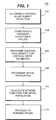
- Figure 1 is a flow chart illustrating a sequence of process steps executed in the initialization phase for identifying optimum control blade positions in accordance with one embodiment of the present invention.
- Figure 2 is a flow chart illustrating a sequence of process steps executed in the running phase for identifying optimum control blade positions in accordance with one embodiment of the present invention.
- the present invention is a method for identifying optimum control blade positioning.
- the method can be generally understood as having two (2) phases.
- the first phase is an initialization phase and the second phase is the running, or search, phase.
- initial control blade positions are identified, and in the running phase, the control blade positions are optimized within the design constraints.
- the present invention is a system including a computer programmed to execute the method described in detail below.
- the method can be practiced, for example, on most any type of computer including even a personal computer.
- the type of computer selected depends primarily on the speed at which the operator desires to have the optimum control blade positions identified and the amount of memory required for any particular operation. Such speed and memory requirements may, of course, vary depending upon the number of reactors being analyzed and the number of control blades in the reactor cores.
- the method is not limited to practice on any one particular type of computer.
- a sequence of process steps 100 executed in the initialization phase for identifying initial control blade positions is illustrated.
- a set of control blades to be positioned within the reactor core is selected 102 for analysis.
- the set of blades identified may, for example, be selected so that the set is symmetric about the core.
- each constraint 104 The design constraints are then identified and acceptable values or ranges are assigned to each constraint 104.
- the reactor peak local thermal power margin design constraint may be 10 percent (10%).
- Reactor peak local power margin depends, at least in part, on the control blade positions and locations. Therefore, the peak local power margin design constraint can be affected based on the control blade position.
- rules also are established for each blade, and such rules specify a direction (e.g., up or down) in which to move a control blade to maximize the cycle energy and/or satisfy a constraint. These rules typically are generic for each reactor and are based primarily upon the experience of the engineer. In defining the rules, each blade is evaluated separately in determining direction.
- the direction rules must be established for each particular loading of each reactor.
- such rules may remain relatively constant over a long period of time, e.g., for many cycles. However, it may be recommended to at least reevaluate such rules for each cycle.
- a criticality weight value 106- is assigned to each blade.
- a control blade that has more of an affect on criticality than another blade is assigned a greater weight than the other blade.
- a control blade located in the core center has more of a direct impact on criticality than a control blade at the core periphery. Therefore, the control blade at the core center is assigned a higher weight than the control blade at the core periphery, in general.
- Each control blade is assigned such a weight based on its impact on criticality.
- An initial population 108 is then determined. Specifically, a random control blade pattern is identified. The random population randomly assigns a position to each control blade. The initial random population can be developed on a purely random basis.
- a fitness function 110 is then determined for each unique control blade positioning member in the random population.
- the fitness function is a representation of how well each member of the random population satisfies all the constraints. For example, a high value fitness function indicates that a member of the population satisfies the constraints whereas a low value fitness function indicates that the member does not satisfy the constraints.
- Figure 2 is a flow chart illustrating a sequence of process steps 200 executed in the running, or search, phase for identifying optimum control blade positions. Process steps 200 are executed subsequent to completion of initialization process steps 100 illustrated in Figure 1. Referring to Figure 2, and for the first iteration, the population (i.e., the control blade positions) is updated 202 to contain the initial population identified in the initialization phase.
- the population i.e., the control blade positions
- the core is then run, i.e., simulated, 204 for each control blade positioning which is a member of the initial population.
- Each constraint is then checked 206 to determine whether the constraints are satisfied by the case just run. If all constraints are satisfied, then the blade positioning is compared to previously determined blade positions to determine whether the blade positioning is unique, or different, from any previously run case 208.
- processing proceeds to determine whether all blade position iterations 210 have been analyzed. If all iterations have not been analyzed, then the second part of the search phase is started. In this second part, the rule base created in the initialization phase is searched to determine the direction to adjust the control blades in order to satisfy the unsatisfied constraints or to be unique. For example, if at the particular blade location, a design constraint is not satisfied, then the position of the blade at the subject core location typically must be changed.
- the rule base may contain a rule that indicates whether the blade should be moved up or down, depending upon the specific conditions created by the particular blade positions.
- control blade position is changed and the population is then updated 202 and processing proceeds through steps 204, 206 and 208 as described above.
- the rule base is searched to determine the direction the blade should be changed in order to maximize cycle energy 212. This means that based on the specific conditions created by the particular blade positions, a rule in the rule base may indicate the direction in which the particular blade should be changed in order to improve cycle energy. Therefore, the rule from the rule base will indicate whether the particular control blade should be moved up or down in order to improve cycle energy.
- control blade is then adjusted, which is sometimes referred to herein as a 1-D (one-dimensional search) adjustment 214.
- a 1-D (one-dimensional search) adjustment 214 is then adjusted.
- the new case is run 216. If every blade position has not been evaluated 218, then another blade is either randomly or sequentially selected for analysis and processing returns to step 214 to perform the above described analysis in connection with steps 214, 216 and 218.
- searching is to identify a most optimum core loading arrangement.
- Such searching can be performing in either a "depth” or "breadth” mode of operation.
- the depth mode once a change has been made that results in an improved core loading arrangement, then the subsequent change is made to such alternative arrangement. That is, processing continues by using the improved position as the "base" position and processing does not return to the initial, less optimum, control blade position. Once all the blade positions have been changed, the blade position arrangement under analysis is then selected as the best arrangement for further processing as described below.
- each alternative control blade position arrangement is analyzed with respect to the initial control blade position arrangement. This means that after evaluation of a new arrangement, and even if the new arrangement is an improvement over the initial arrangement, the next arrangement considered is a variation of the initial arrangement. That is, processing returns to the initial arrangement and selects another control blade position to change. Once all the control blade positions have been changed, then the best alternative arrangement is selected for further processing as described below.
- local random initial positioning arrangements 220 are generated and processing returns to step 214.
- the local random positions selected are close to the base positionings unlike random positions which may be selected in connection with step 202 in which random positioning can be very different from any positioning previously considered, i.e., a "global" search.
- the most optimum control blade positioning arrangement identified up to this point in processing is selected for comparison to the random initial arrangements.
- Such "random jumps" are made to potentially identify previously unconsidered arrangements that may be more optimum than the most optimum arrangement identified up to that point in processing. For example, a particular randomly selected blade position may have its position changed.
- step 216 determines whether the randomly selected arrangement is more optimum than the best known arrangement.
- the number of random jumps executed may be selected by the operator based on the amount of time available for identifying the most optimum arrangement.
- the number of random jumps may vary, for example, from as few as five (5) to as many as twenty (20). If the number of random jumps selected have been executed, then processing returns to step 202.
- the population is updated to the most recently identified case, i.e., the then best known case, which is then run 204. If the constraints are satisfied 206 and if the case is not unique 208, and all iterations are exhausted 210, then the best case is identified to be the present case 222.
- the initial population is continually replaced with a better population with a better population where the least fit members have been removed and replaced with more fit members such that the overall fitness of the population improves.
- the above described method for identifying the optimum control blade positioning arrangement reduces the amount of engineer time required to identify a control blade positioning arrangement which optimize cycle energy and satisfies all design constraints. Importantly, such method is believed to be applicable to a wide range of reactors for consistently and reliably identifying optimum control blade positioning arrangements.
Abstract
Description
Claims (7)
- A system for identifying a control blade positioning arrangement for a reactor core, the control blade positioning arrangement being required to satisfy predetermined design constraints, said system comprising a computer having a memory storage, said memory storage having stored therein a weight assigned to each blade based on the affect such blade has on criticality, values assigned to each predetermined design constraint, and rules for control blade positions which specify a direction in which to move a control blade to maximize the cycle energy or satisfy a predetermined constraint, or both, said computer programmed to:determine an initial population of control blade position members (108);optimize the initial population to improve energy efficiency of the population and to satisfy the design constraints, said population optimizing performed by:(i) creating a new population including at least one new member;(ii) determining a fitness function (110) for the new population;(iii) repeating steps (i) and (ii) until a population is identified that has a predetermined fitness level;(iv) creating new populations by performing a 1-D search (214) adjustment starting with the identified population having the predetermined fitness level.
- A system in accordance with Claim 1 wherein to determine an initial population of control blade position members, said computer is further programmed to:select a control blade subset (102);assign weights to each selected control blade (106);assign values to each predetermined constraint (104);create rules for each selected control blade to specify a direction in which to move each blade to maximize the cycle energy or satisfy a predetermined constraint, or both (104);initially simulate reactor operation wherein each control blade is located at a random location (204); anddetermine initial values for cycle energy and design constraints for the initial control blade location arrangement (206).
- A system in accordance with Claim 1 or 2, wherein to create a new population including at least one new member, said computer is further programmed to:determine whether the current control blade positioning arrangement satisfies the design constraints (206); andif at least one design constraint is not satisfied (206), then search the rules to determine a direction in which to move a selected control blade in order to satisfy the constraint.
- A system in accordance with Claim 1 or 2, wherein to create a new population including at least one new member, said computer is further programmed to:
search the rules to determine a direction in which to move a selected control blade if all the design constraints are satisfied and if the control blade positioning arrangement is not unique (208). - A system in accordance with Claim 1 or 2, wherein to create a new population including at least one new member, said computer is further programmed to:
search the rules to determine a direction in which to move a selected control blade to improve cycle energy if all the design constraints have been satisfied (206) and if the control blade positioning is unique (208). - A system in accordance with Claim 1 or 2, wherein to create a new populations by performing a 1-D search adjustment (214), said computer is programmed to operate in a depth mode, the depth mode providing that once a change has been made that results in an improved core loading arrangement, then any subsequent change is made to such alternative arrangement in performing steps (ii) - (vi).
- A system in accordance with Claim 1 or 2, wherein to create a new populations by performing a 1-D search adjustment (214), said computer is programmed to operate in a breadth mode, the breadth mode providing that -each alternative core loading arrangement is analyzed with respect to the initial control blade positioning arrangement in performing steps (ii) - (iv).
Applications Claiming Priority (2)
| Application Number | Priority Date | Filing Date | Title |
|---|---|---|---|
| US08/695,007 US5790616A (en) | 1996-08-09 | 1996-08-09 | Method and system for determining nuclear reactor core control blade positioning |
| US695007 | 1996-08-09 |
Publications (2)
| Publication Number | Publication Date |
|---|---|
| EP0823712A1 true EP0823712A1 (en) | 1998-02-11 |
| EP0823712B1 EP0823712B1 (en) | 2001-11-28 |
Family
ID=24791183
Family Applications (1)
| Application Number | Title | Priority Date | Filing Date |
|---|---|---|---|
| EP97306079A Expired - Lifetime EP0823712B1 (en) | 1996-08-09 | 1997-08-08 | Method and system for determining nuclear reactor core control blade positioning |
Country Status (5)
| Country | Link |
|---|---|
| US (1) | US5790616A (en) |
| EP (1) | EP0823712B1 (en) |
| JP (1) | JPH10123284A (en) |
| DE (1) | DE69708554T2 (en) |
| TW (1) | TW360877B (en) |
Cited By (8)
| Publication number | Priority date | Publication date | Assignee | Title |
|---|---|---|---|---|
| EP1113457A1 (en) * | 1999-12-30 | 2001-07-04 | General Electric Company | System and method for optimization of multiple operational control-variables for a nuclear reactor |
| US6931090B2 (en) * | 2003-02-25 | 2005-08-16 | Westinghouse Electric Company Llc | Method of establishing a nuclear reactor core fuel assembly loading pattern |
| EP1677314A2 (en) * | 2004-12-30 | 2006-07-05 | Global Nuclear Fuel-Americas, LLC | Method of determining nuclear reactor core design with reduced control blade density. |
| EP1443523A3 (en) * | 2003-01-31 | 2007-07-25 | Global Nuclear Fuel-Americas, LLC | A method of improving nuclear reactor performance |
| EP1435626A3 (en) * | 2002-12-18 | 2008-02-20 | Global Nuclear Fuel-Americas, LLC | Method and arrangement for developing rod patterns in nuclear reactors |
| US7487133B2 (en) | 2002-09-19 | 2009-02-03 | Global Nuclear Fuel - Americas, Llc | Method and apparatus for adaptively determining weight factors within the context of an objective function |
| US7555092B2 (en) | 2001-11-07 | 2009-06-30 | General Electric Company | System and method for continuous optimization of control-variables during operation of a nuclear reactor |
| US8041548B2 (en) | 2004-12-30 | 2011-10-18 | Global Nuclear Fuels-Americas, LLC | Method and apparatus for evaluating a proposed solution to a constraint problem for a nuclear reactor involving channel deformation |
Families Citing this family (10)
| Publication number | Priority date | Publication date | Assignee | Title |
|---|---|---|---|---|
| US6404437B1 (en) | 1999-09-10 | 2002-06-11 | General Electric Company | Nuclear reactor core performance data visualization system |
| US6611572B2 (en) | 2000-12-29 | 2003-08-26 | Global Nuclear Fuel - Americas, L.L.C. | Determination of operating limit minimum critical power ratio |
| US8873698B2 (en) * | 2002-12-18 | 2014-10-28 | Global Nuclear Fuel—Americas, LLC | Computer-implemented method and system for designing a nuclear reactor core which satisfies licensing criteria |
| US9047995B2 (en) * | 2002-12-18 | 2015-06-02 | Global Nuclear Fuel—Americas, LLC | Method and system for designing a nuclear reactor core for uprated power operations |
| US7280946B2 (en) * | 2003-04-30 | 2007-10-09 | Global Nuclear Fuel-Americas, Llc | Method and arrangement for determining pin enrichments in fuel bundle of nuclear reactor |
| US7672815B2 (en) * | 2004-12-30 | 2010-03-02 | Global Nuclear Fuel - Americas, Llc | Method and apparatus for evaluating a proposed solution to a constraint problem |
| US7620139B2 (en) * | 2005-06-30 | 2009-11-17 | Global Nuclear Fuel - Americas, Llc | Method of improving nuclear reactor performance during reactor core operation |
| US8185836B2 (en) * | 2006-02-16 | 2012-05-22 | Global Nuclear Fuel - Americas Llc | Display, visualization, and processing tool for channel distortion and cell friction mitigation |
| US7472045B2 (en) * | 2006-12-13 | 2008-12-30 | Global Nuclear Fuel—Americas, LLC | Method for perturbating a nuclear reactor core fuel bundle design to generate a group of designs |
| US8433029B2 (en) | 2007-12-14 | 2013-04-30 | Global Nuclear Fuel—Americas, LLC | Determination of safety limit minimum critical power ratio |
Citations (4)
| Publication number | Priority date | Publication date | Assignee | Title |
|---|---|---|---|---|
| FR2244235A1 (en) * | 1973-09-17 | 1975-04-11 | Siemens Ag | |
| EP0150096A2 (en) * | 1984-01-20 | 1985-07-31 | Westinghouse Electric Corporation | Method and apparatus for continuous on-line monitoring of power distribution in a nuclear reactor core |
| JPH01185483A (en) * | 1988-01-21 | 1989-07-25 | Hitachi Ltd | Control rod operation monitor |
| EP0369865A1 (en) * | 1988-11-14 | 1990-05-23 | Framatome | Control method for a pressurised-water nuclear reactor |
Family Cites Families (3)
| Publication number | Priority date | Publication date | Assignee | Title |
|---|---|---|---|---|
| US4717528A (en) * | 1985-02-19 | 1988-01-05 | Westinghouse Electric Corp. | Control rod control system |
| JP2579996B2 (en) * | 1988-04-12 | 1997-02-12 | 株式会社東芝 | Core state prediction device |
| US5586157A (en) * | 1993-12-28 | 1996-12-17 | The University Of Chicago | Method and apparatus for manufacturing gas tags |
-
1996
- 1996-08-09 US US08/695,007 patent/US5790616A/en not_active Expired - Lifetime
-
1997
- 1997-05-19 TW TW086106652A patent/TW360877B/en not_active IP Right Cessation
- 1997-08-08 EP EP97306079A patent/EP0823712B1/en not_active Expired - Lifetime
- 1997-08-08 DE DE69708554T patent/DE69708554T2/en not_active Expired - Fee Related
- 1997-08-08 JP JP9214269A patent/JPH10123284A/en active Pending
Patent Citations (4)
| Publication number | Priority date | Publication date | Assignee | Title |
|---|---|---|---|---|
| FR2244235A1 (en) * | 1973-09-17 | 1975-04-11 | Siemens Ag | |
| EP0150096A2 (en) * | 1984-01-20 | 1985-07-31 | Westinghouse Electric Corporation | Method and apparatus for continuous on-line monitoring of power distribution in a nuclear reactor core |
| JPH01185483A (en) * | 1988-01-21 | 1989-07-25 | Hitachi Ltd | Control rod operation monitor |
| EP0369865A1 (en) * | 1988-11-14 | 1990-05-23 | Framatome | Control method for a pressurised-water nuclear reactor |
Non-Patent Citations (1)
| Title |
|---|
| PATENT ABSTRACTS OF JAPAN vol. 013, no. 471 (P - 949) 25 October 1989 (1989-10-25) * |
Cited By (11)
| Publication number | Priority date | Publication date | Assignee | Title |
|---|---|---|---|---|
| EP1113457A1 (en) * | 1999-12-30 | 2001-07-04 | General Electric Company | System and method for optimization of multiple operational control-variables for a nuclear reactor |
| US6748348B1 (en) | 1999-12-30 | 2004-06-08 | General Electric Company | Design method for nuclear reactor fuel management |
| US7555092B2 (en) | 2001-11-07 | 2009-06-30 | General Electric Company | System and method for continuous optimization of control-variables during operation of a nuclear reactor |
| US7487133B2 (en) | 2002-09-19 | 2009-02-03 | Global Nuclear Fuel - Americas, Llc | Method and apparatus for adaptively determining weight factors within the context of an objective function |
| EP1435626A3 (en) * | 2002-12-18 | 2008-02-20 | Global Nuclear Fuel-Americas, LLC | Method and arrangement for developing rod patterns in nuclear reactors |
| EP1443523A3 (en) * | 2003-01-31 | 2007-07-25 | Global Nuclear Fuel-Americas, LLC | A method of improving nuclear reactor performance |
| US7693249B2 (en) | 2003-01-31 | 2010-04-06 | Global Nuclear Fuel - Americas, Llc | Method of improving nuclear reactor performance |
| US6931090B2 (en) * | 2003-02-25 | 2005-08-16 | Westinghouse Electric Company Llc | Method of establishing a nuclear reactor core fuel assembly loading pattern |
| EP1677314A2 (en) * | 2004-12-30 | 2006-07-05 | Global Nuclear Fuel-Americas, LLC | Method of determining nuclear reactor core design with reduced control blade density. |
| EP1677314A3 (en) * | 2004-12-30 | 2007-10-31 | Global Nuclear Fuel-Americas, LLC | Method of determining nuclear reactor core design with reduced control blade density. |
| US8041548B2 (en) | 2004-12-30 | 2011-10-18 | Global Nuclear Fuels-Americas, LLC | Method and apparatus for evaluating a proposed solution to a constraint problem for a nuclear reactor involving channel deformation |
Also Published As
| Publication number | Publication date |
|---|---|
| DE69708554D1 (en) | 2002-01-10 |
| EP0823712B1 (en) | 2001-11-28 |
| TW360877B (en) | 1999-06-11 |
| DE69708554T2 (en) | 2002-08-22 |
| US5790616A (en) | 1998-08-04 |
| JPH10123284A (en) | 1998-05-15 |
Similar Documents
| Publication | Publication Date | Title |
|---|---|---|
| EP0823712B1 (en) | Method and system for determining nuclear reactor core control blade positioning | |
| EP0786782B1 (en) | Method for determining nuclear core loading arrangement | |
| US6748348B1 (en) | Design method for nuclear reactor fuel management | |
| Parks | An intelligent stochastic optimization routine for nuclear fuel cycle design | |
| US7685079B2 (en) | Methods for evaluating robustness of solutions to constraint problems | |
| Yamamoto | A quantitative comparison of loading pattern optimization methods for in-core fuel management of PWR | |
| EP1524674A1 (en) | A method for reactor simulation | |
| Kim et al. | Optimization of core reload design for low-leakage fuel management in pressurized water reactors | |
| Motoda et al. | Optimization of refueling schedule for light-water reactors | |
| Terney et al. | The design of reload cores using optimal control theory | |
| Snipes et al. | H mode power threshold database for ITER | |
| MXPA04000973A (en) | Method of improving nuclear reactor performance. | |
| Kobayashi et al. | Optimization of boiling water reactor loading pattern using two-stage genetic algorithm | |
| Jagawa et al. | Boiling water reactor loading pattern optimization using simple linear perturbation and modified tabu search methods | |
| Guler et al. | Development of the VVER core loading optimization system | |
| Stout | Optimization of in-core nuclear fuel management in a pressurized water reactor | |
| Colletti et al. | Iterative solution to the optimal poison management problem in pressurized water reactors | |
| Comes et al. | Out-of-core fuel cycle optimization for nonequilibrium cycles | |
| Naughton et al. | TRIGA core management model | |
| Yilmaz | Multi level optimization of burnable poison utilization for advanced PWR fuel management | |
| Do et al. | An evolutionary optimization of the refueling simulation for a CANDU reactor | |
| Lin et al. | Pressurized water reactor reload design by an expert system | |
| Thomsen | Self-management, an approach to optimum care management of thermal reactors by means of ideal burn-up distributions | |
| Downar et al. | Explicit burnable absorber modeling for pressurized water reactor core reload design applications | |
| Haddock et al. | AGR fuel management using PANTHER |
Legal Events
| Date | Code | Title | Description |
|---|---|---|---|
| PUAI | Public reference made under article 153(3) epc to a published international application that has entered the european phase |
Free format text: ORIGINAL CODE: 0009012 |
|
| AK | Designated contracting states |
Kind code of ref document: A1 Designated state(s): DE FI SE |
|
| 17P | Request for examination filed |
Effective date: 19980811 |
|
| AKX | Designation fees paid |
Free format text: DE FI SE |
|
| RBV | Designated contracting states (corrected) |
Designated state(s): DE FI SE |
|
| GRAG | Despatch of communication of intention to grant |
Free format text: ORIGINAL CODE: EPIDOS AGRA |
|
| 17Q | First examination report despatched |
Effective date: 20000824 |
|
| GRAG | Despatch of communication of intention to grant |
Free format text: ORIGINAL CODE: EPIDOS AGRA |
|
| GRAH | Despatch of communication of intention to grant a patent |
Free format text: ORIGINAL CODE: EPIDOS IGRA |
|
| GRAH | Despatch of communication of intention to grant a patent |
Free format text: ORIGINAL CODE: EPIDOS IGRA |
|
| GRAA | (expected) grant |
Free format text: ORIGINAL CODE: 0009210 |
|
| AK | Designated contracting states |
Kind code of ref document: B1 Designated state(s): DE FI SE |
|
| REF | Corresponds to: |
Ref document number: 69708554 Country of ref document: DE Date of ref document: 20020110 |
|
| PLBE | No opposition filed within time limit |
Free format text: ORIGINAL CODE: 0009261 |
|
| STAA | Information on the status of an ep patent application or granted ep patent |
Free format text: STATUS: NO OPPOSITION FILED WITHIN TIME LIMIT |
|
| 26N | No opposition filed | ||
| PGFP | Annual fee paid to national office [announced via postgrant information from national office to epo] |
Ref country code: FI Payment date: 20070830 Year of fee payment: 11 |
|
| PGFP | Annual fee paid to national office [announced via postgrant information from national office to epo] |
Ref country code: SE Payment date: 20070829 Year of fee payment: 11 Ref country code: DE Payment date: 20071001 Year of fee payment: 11 |
|
| EUG | Se: european patent has lapsed | ||
| PG25 | Lapsed in a contracting state [announced via postgrant information from national office to epo] |
Ref country code: FI Free format text: LAPSE BECAUSE OF NON-PAYMENT OF DUE FEES Effective date: 20080808 |
|
| PG25 | Lapsed in a contracting state [announced via postgrant information from national office to epo] |
Ref country code: DE Free format text: LAPSE BECAUSE OF NON-PAYMENT OF DUE FEES Effective date: 20090303 |
|
| PG25 | Lapsed in a contracting state [announced via postgrant information from national office to epo] |
Ref country code: SE Free format text: LAPSE BECAUSE OF NON-PAYMENT OF DUE FEES Effective date: 20080809 |