EP0802487A2 - Hot plug computer system protection circuit - Google Patents
Hot plug computer system protection circuit Download PDFInfo
- Publication number
- EP0802487A2 EP0802487A2 EP97302535A EP97302535A EP0802487A2 EP 0802487 A2 EP0802487 A2 EP 0802487A2 EP 97302535 A EP97302535 A EP 97302535A EP 97302535 A EP97302535 A EP 97302535A EP 0802487 A2 EP0802487 A2 EP 0802487A2
- Authority
- EP
- European Patent Office
- Prior art keywords
- power
- interface card
- protection circuit
- current
- voltage
- Prior art date
- Legal status (The legal status is an assumption and is not a legal conclusion. Google has not performed a legal analysis and makes no representation as to the accuracy of the status listed.)
- Withdrawn
Links
Images


Classifications
-
- G—PHYSICS
- G06—COMPUTING; CALCULATING OR COUNTING
- G06F—ELECTRIC DIGITAL DATA PROCESSING
- G06F13/00—Interconnection of, or transfer of information or other signals between, memories, input/output devices or central processing units
- G06F13/38—Information transfer, e.g. on bus
- G06F13/40—Bus structure
- G06F13/4063—Device-to-bus coupling
- G06F13/4068—Electrical coupling
- G06F13/4081—Live connection to bus, e.g. hot-plugging
-
- H—ELECTRICITY
- H02—GENERATION; CONVERSION OR DISTRIBUTION OF ELECTRIC POWER
- H02H—EMERGENCY PROTECTIVE CIRCUIT ARRANGEMENTS
- H02H9/00—Emergency protective circuit arrangements for limiting excess current or voltage without disconnection
- H02H9/001—Emergency protective circuit arrangements for limiting excess current or voltage without disconnection limiting speed of change of electric quantities, e.g. soft switching on or off
- H02H9/004—Emergency protective circuit arrangements for limiting excess current or voltage without disconnection limiting speed of change of electric quantities, e.g. soft switching on or off in connection with live-insertion of plug-in units
Definitions
- the present invention relates to protection circuits for computer systems having peripheral expansion slots. More specifically, the present invention relates to a protection circuit for a computer system having an interface card-receiving socket such as a peripheral component interconnect slot that receives peripheral component interconnect cards.
- PCI peripheral component interconnect
- expansion cards can be plugged into the computer system while the computer system is powered and running.
- the ability to hot plug PCI cards is especially desirable in network computer systems. This allows maintenance to be performed on a server in a network computer system without having to power down the server. For example the addition of a PCI expansion card or the removal and replacement an existing defective PCI expansion card can be performed while the server of the network computer system is running thereby allowing users to continue to use the system during the maintenance period.
- a protection circuit for a computer having a power supply and an interface card-receiving socket for receiving an interface card
- the protection circuit comprising a current monitor for monitoring the levels of current drawn by an interface card when the interface card is received at the interface card-receiving socket; and a disconnector coupled to receive indications of the current levels monitored by the current monitor, and to disconnect the power supply from the interface card when the indications of the current levels monitored by said current monitor are beyond a selected level.
- the present invention overcomes the above identified problems as well as other shortcomings and deficiencies or existing technologies by providing a PCI hot plug protection circuit that is able to monitor the current drawn at each of the power rails of the PCI expansion slot and that can shut off power to the expansion slot when the current drawn at any of the power rails go beyond a selected range.
- the present invention further provides a computer system having: PCI expansion cards; PCI expansion slots with four power rails to supply power to the PCI expansion cards; a current monitor that monitors the current levels drawn by the PCI expansion card at each power rail; an inrush current controller for controlling the initial current applied to each of the power rails when power is initially applied to an expansion card; a voltage monitor that monitors the voltage levels applied to selected power rails; and a disconnector for disconnecting the power to the PCI expansion slot when either the current level drawn by the PCI expansion card at any of the power rails goes beyond a selected range or when the voltage levels at any of the selected monitored power rails do not reach or fall below a selected operating potential.
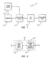
- FIG. 1 there is shown a block diagram illustrating a computer system 110 which includes a power supply 112, a computer 114, a protection circuit 116, a peripheral component interconnect (hereinafter PCI) slot 118 and a peripheral card 120.
- PCI peripheral component interconnect
- Computer 114 is interconnected between protection circuit 116 and power supply 112.
- Power supply 112 provides at least a portion of the power to the operate computer system 110.
- PCI slot 118 is connected to protection circuit 116 and is configured to receive a PCI expansion card such as peripheral card 120.
- PCI slot 118 is a standard PCI slot and includes +5V, +3.3V, +12V and -12V power rails for supplying power to peripheral card when connected.
- the present invention is not limited to a single protection circuit, PCI slot, and peripheral card, but rather could be practiced by one skilled in the art to include multiple protection circuits, multiple PCI slots, and multiple peripheral cards all within the computer system.
- protection circuit 116 includes a power rail switch 210 connected with an overcurrent detector 212.
- protection circuit 116 allows a peripheral card to be connected to PCI slot 118 while the computer system is powered and running and prevents the computer system from failing if the added peripheral card is defective such as by having an effective short therein.
- the overcurrent detector 212 of protection circuit 116 monitors currents and voltages being supplied to the peripheral card 120 when it is connected to PCI slot 118. When any of the monitored currents are beyond a selected value or if any of the monitored voltages are below a selected value, monitor 212 generates a fault signal which is used to interrupt the CPU of the computer system 110, and also generates and sends disconnect signal to power rail switch 210 whereby power rail switch 210 disconnects the power to PCI slot 118.
- Power rail switch 210 also controls the in-rush current, i.e. the initial current that is supplied to the peripheral card 120 when it is initially connected to PCI slot 118.
- the in-rush current is limited during power up so that overcurrent detector 212 does not trip.
- power rail switch 210 includes input terminals 312, 314, 316, 318 and 320, with terminals 312, 314, 318 and 320 receiving power signals from power supply 112.
- Power rail switch 210 further includes output terminals 322, 324, 326 and 328, controllers 330, 332 and 334 for controlling the outputs to the output terminals, and a level shifter 336.
- input terminal 312 receives a -12V signal
- input terminal 314 receives a +12V signal
- input terminal 318 receives a +5V signal
- input terminal 320 receives a +3.3V signal
- input terminal 316 receives a power on signal
- Output terminal 322 is a -12V output terminal
- output terminal 324 is a +5V output terminal
- output terminal 326 is a +3.3V output terminal
- output terminal 328 is a +12V output terminal.
- Controller 330 controls the output signals to output terminals 322 and 328, while control 332 controls the output signal to output terminal 324 and control 334 controls the output to output terminal 326.
- Power rail switch 210 further includes FET 338, and positive temperature coefficient (PTC) resistors 340 and 342.
- PTC resistors 340 and 342 are used as secondary overcurrent protectors by abruptly increasing in resistance when a select overcurrent condition is detected. This is preferred to be higher than required to trip overcurrent detector 212. This is because, if a PTC resistor is tripped, it takes several hours for its resistance to return to its initial value.
- Controller 330 includes resistors 344, 346 and 348, capacitors 350 and 352, and FETs 354 and 356.
- Controller 332 includes FETs 358 and 360, capacitor 361, and resistor 362.
- Controller 334 includes FETs 364 and 366, capacitor 367 and resistor 368.
- Level shifter 336 includes FET 370 and resistor 372.
- capacitor 352 and resistor 348 slowly ramp the gate voltage of FET 356, thereby slowing turning on FET 356. This control the amount of in-rush-current associated with the power rail supplying the -12V to input terminal 312. After FET 356 has been turned on, the voltage signal sent from controller 330 to output terminal 322 will reach a -12V signal.
- Controllers 332 and 334 also operate in a similar manner.
- a high power-enable signal is received at input terminal 316, the signal is passed high through noninverting buffer 374 to each of controllers 332 and 334.
- capacitor 361 and resistor 362 slowly ramp the gate voltages of FETs 358 and 360, thereby slowing turning on FETs 358 and 360. This controls the amount of in-rush current associated with the one power rail supplying the +5V to input terminal 318.
- the voltage signal from controller 332 to output terminal 324 will reach a +5V signal.
- capacitor 367 and resistor 368 slowly ramp the gate voltages of FETS 364 and 366, thereby slowing turning on FETs 364 and 366. This control the amount of in-rush current associated with the power rail supplying the +3.3V to input terminal 320. After FETs 364 and 366 have been turned on, the voltage signal from controller 344 to output terminal 326 will reach a +3.3V signal.
- controllers 330, 332 and 334 are disconnected quickly because of the diodes associated therewith.
- detector 212 includes input terminals 412, 414, 416, 418, 420, 422 and 424, with input terminals 414, 416, 420 and 424 being connected to output terminals 326, 324, 328 and 322 of power rail switch 210, respectively.
- Input terminal 412 is connected to power supply to receive +12V signal
- input terminal 418 is coupled to receive a bus enable signal, the bus enable signal being high when the slot has reached a stable operating state
- input terminal 422 is coupled to receive a power enable signal, the power enable signal being high when power is to be supplied to the slot.
- Overcurrent detector 212 further includes output terminals 426, 428, 430, 432, 434 and 436, with output terminals 426, 428, 430 and 436 being connected to peripheral card 120 and supplying thereto +3.3V, +5V, -12V and +12V signals respectively.
- Overcurrent detector 212 further includes voltage level detectors 440, 442, 444 and 446, an under voltage detector 438, and a flip-flop 448.
- Voltage level detectors 440 442, 444 and 446 are coupled to monitor the input signals received at input terminals 414, 416, 420 and 424 respectively and to monitor output signals at output terminals 426, 428, 436 and 430 respectively.
- the under voltage detector 438 is coupled to operate with voltage level detectors 440 and 442.
- the voltage level detectors 440, 442, 444 and 446 monitor the current drawn by each of the power rails and when an overcurrent is detected at any of the voltage level detectors, i.e. when the current passing through any of the voltage level detectors goes beyond a selected level, flip-flop 448 will be enabled and generate a low power-on signal at output terminal 432 (which is connected to input terminal 316 of power rail switch 210). Power rail switch 210 will then disconnect power from slot 118 by turning off controllers 330, 332 and 334 (see FIG. 3).
- Voltage level detector 440 includes a voltage divider 448 and a comparator 450.
- An overcurrent condition is detected by using comparator 450 to monitor the voltage drop across resistor 452 of voltage divider 448. When the voltage drop across resistor 452 is sufficient to bring the negative input of comparator 450 above the positive input of comparator 450 by a user defined amount of voltage an overcurrent condition exists. When this occurs the output of comparator 450 is pulled low, FET 454 is turned off, triggering flip-flop 448 to latch and to send a low power-on signal out of output terminal 432, wherein power rail switch 210 will disconnect power from slot 118 by turning off controllers 330, 332 and 334.
- a fault indicator is also sent to the CPU from output terminal 434.
- Voltage level detectors 442, 444 and 446 generally operate in a similar manner as voltage level detector 440.
- the under voltage detector 438 detects power failure on the +5V and the +3.3V power rails.
- input terminal 418 receives a bus enable signal, a high signal to enable the under voltage detector 438 and a low signal to disable the under voltage detector 438.
- under voltage detector 438 is disabled during initial power-up so that under voltage detector 438 does not trip overcurrent detector.
- the bus enable signal goes high, enabling under voltage detector 438.
- the corresponding diode (diode 454 or 456) will pull the signal at the negative input of the comparator in the corresponding voltage level detectors (440 or 442) high enough to pull the output of the comparators low.
- FET 454 is then turned off, triggering flip-flop 448 to latch and to send a low power-on signal out of output terminal 432.
- a fault indicator is also sent in to the CPU in the computer from output terminal 434, wherein power rail switch 210 will disconnect power from slot 118 by turning off controllers 330, 332 and 334.
- a fault indicator is also sent to the CPU from output terminal 434.
- Voltage level detectors 442, 444 and 446 generally operate in a similar manner as voltage level detector 440.
- bias circuitry 458 prevents false overcurrent indications when power-on is initially set high.
Abstract
Description
- The present invention relates to protection circuits for computer systems having peripheral expansion slots. More specifically, the present invention relates to a protection circuit for a computer system having an interface card-receiving socket such as a peripheral component interconnect slot that receives peripheral component interconnect cards.
- Many existing computer systems utilize peripheral component interconnect (PCI) expansion slots and cards. The PCI utilizes power rails to transfer power from the computer system through the expansion slot to the card. Generally +5V, +3.3V, +12V and -12V power rails are used.
- In computer systems utilizing a PCI environment, expansion cards can be plugged into the computer system while the computer system is powered and running. As can be appreciated, the ability to hot plug PCI cards is especially desirable in network computer systems. This allows maintenance to be performed on a server in a network computer system without having to power down the server. For example the addition of a PCI expansion card or the removal and replacement an existing defective PCI expansion card can be performed while the server of the network computer system is running thereby allowing users to continue to use the system during the maintenance period.
- However, if the added PCI expansion card is defective or if a problem arises with the PCI expansion card such as if an effective short is caused by the card's bypass capacitors between its power rails and ground, then when the card is hot plugged into the network computer system, a system failure could result. Further if an installed PCI expansion card becomes defective during use, a system failure could also result.
- Therefore it is proposed, according to the present invention, to monitor the current drawn by the PCI expansion card at each of the power rails and, if at any time the current drawn at any of these power rails is beyond a selected range, to quickly turn off the power to the PCI expansion slot or to the PCI expansion card so that the entire computer system does not fail.
- According to the present invention therefore there is provided a protection circuit for a computer having a power supply and an interface card-receiving socket for receiving an interface card, the protection circuit comprising a current monitor for monitoring the levels of current drawn by an interface card when the interface card is received at the interface card-receiving socket; and a disconnector coupled to receive indications of the current levels monitored by the current monitor, and to disconnect the power supply from the interface card when the indications of the current levels monitored by said current monitor are beyond a selected level.
- The present invention overcomes the above identified problems as well as other shortcomings and deficiencies or existing technologies by providing a PCI hot plug protection circuit that is able to monitor the current drawn at each of the power rails of the PCI expansion slot and that can shut off power to the expansion slot when the current drawn at any of the power rails go beyond a selected range.
- The present invention further provides a computer system having: PCI expansion cards; PCI expansion slots with four power rails to supply power to the PCI expansion cards; a current monitor that monitors the current levels drawn by the PCI expansion card at each power rail; an inrush current controller for controlling the initial current applied to each of the power rails when power is initially applied to an expansion card; a voltage monitor that monitors the voltage levels applied to selected power rails; and a disconnector for disconnecting the power to the PCI expansion slot when either the current level drawn by the PCI expansion card at any of the power rails goes beyond a selected range or when the voltage levels at any of the selected monitored power rails do not reach or fall below a selected operating potential.
- A more complete understanding of the method and apparatus of the present invention may be had by reference to the following detailed description in conjunction with the accompanying drawings in which:
- Figure 1 is a block diagram illustrating a computer system utilizing the present invention;
- Figure 2 is a more detailed block diagram illustrating the protection circuit shown in FIG. 1;
- Figure 3 is schematic diagram illustrating the in-rush current controller shown in FIG. 2; and
- Figure 4 is a schematic diagram illustrating the current and voltage monitor shown in FIG. 2.
- Referring now to FIG. 1, there is shown a block diagram illustrating a
computer system 110 which includes apower supply 112, acomputer 114, aprotection circuit 116, a peripheral component interconnect (hereinafter PCI)slot 118 and aperipheral card 120. -
Computer 114 is interconnected betweenprotection circuit 116 andpower supply 112.Power supply 112 provides at least a portion of the power to the operatecomputer system 110.PCI slot 118 is connected toprotection circuit 116 and is configured to receive a PCI expansion card such asperipheral card 120. -
PCI slot 118 is a standard PCI slot and includes +5V, +3.3V, +12V and -12V power rails for supplying power to peripheral card when connected. - The present invention is not limited to a single protection circuit, PCI slot, and peripheral card, but rather could be practiced by one skilled in the art to include multiple protection circuits, multiple PCI slots, and multiple peripheral cards all within the computer system.
- Referring now to FIG. 2, there is shown a block diagram illustrating in more
detail protection circuit 116 as shown in FIG. 1. As depictedprotection circuit 116 includes apower rail switch 210 connected with anovercurrent detector 212. - In general operation,
protection circuit 116 allows a peripheral card to be connected toPCI slot 118 while the computer system is powered and running and prevents the computer system from failing if the added peripheral card is defective such as by having an effective short therein. Theovercurrent detector 212 ofprotection circuit 116 monitors currents and voltages being supplied to theperipheral card 120 when it is connected toPCI slot 118. When any of the monitored currents are beyond a selected value or if any of the monitored voltages are below a selected value,monitor 212 generates a fault signal which is used to interrupt the CPU of thecomputer system 110, and also generates and sends disconnect signal topower rail switch 210 wherebypower rail switch 210 disconnects the power toPCI slot 118. -
Power rail switch 210 also controls the in-rush current, i.e. the initial current that is supplied to theperipheral card 120 when it is initially connected toPCI slot 118. The in-rush current is limited during power up so thatovercurrent detector 212 does not trip. A more detailed description ofpower rail switch 210 andovercurrent detector 212 and their operations are given below with reference to FIGS. 3 and 4 respectively. - Referring now to FIG. 3, there is illustrated a schematic diagram of
power rail switch 210 shown in FIG. 2. As depictedpower rail switch 210 includesinput terminals terminals power supply 112.Power rail switch 210 further includesoutput terminals controllers level shifter 336. - In this particular embodiment,
input terminal 312 receives a -12V signal,input terminal 314 receives a +12V signal,input terminal 318 receives a +5V signal, andinput terminal 320 receives a +3.3V signal, whileinput terminal 316 receives a power on signal. -
Output terminal 322 is a -12V output terminal,output terminal 324 is a +5V output terminal,output terminal 326 is a +3.3V output terminal, andoutput terminal 328 is a +12V output terminal. -
Controller 330 controls the output signals tooutput terminals control 332 controls the output signal tooutput terminal 324 andcontrol 334 controls the output tooutput terminal 326. -
Power rail switch 210 further includesFET 338, and positive temperature coefficient (PTC)resistors PTC resistors overcurrent detector 212. This is because, if a PTC resistor is tripped, it takes several hours for its resistance to return to its initial value. -
Controller 330 includesresistors capacitors Controller 332 includesFETs 358 and 360,capacitor 361, andresistor 362.Controller 334 includesFETs 364 and 366,capacitor 367 andresistor 368.Level shifter 336 includes FET 370 and resistor 372. - In operation, when power is first applied to power rail switch, the power on signal received at
input terminal 316 is high. This enhances the channel of FET 338 bringing the signal low with respect to ground. The low signal pulls down on the gate of p-channel FET 354, wherebycapacitor 350 andresistors input terminal 314 thereby slowly ramping the gate voltage ofFET 354, thereby slowing turning onFET 354. This controls the amount of in-rush current associated with the power rail supplying the +12V toinput terminal 314. After FET 354 has been turned on, the voltage signal sent fromcontroller 330 tooutput terminal 328 will reach a +12V signal. - Similarly and simultaneously within
controller 330,capacitor 352 andresistor 348 slowly ramp the gate voltage ofFET 356, thereby slowing turning onFET 356. This control the amount of in-rush-current associated with the power rail supplying the -12V toinput terminal 312. After FET 356 has been turned on, the voltage signal sent fromcontroller 330 tooutput terminal 322 will reach a -12V signal. -
Controllers input terminal 316, the signal is passed high throughnoninverting buffer 374 to each ofcontrollers controller 332,capacitor 361 andresistor 362 slowly ramp the gate voltages ofFETs 358 and 360, thereby slowing turning onFETs 358 and 360. This controls the amount of in-rush current associated with the one power rail supplying the +5V toinput terminal 318. AfterFETs 358 and 360 have been turned on, the voltage signal fromcontroller 332 tooutput terminal 324 will reach a +5V signal. - Within
controller 334,capacitor 367 andresistor 368 slowly ramp the gate voltages ofFETS 364 and 366, thereby slowing turning onFETs 364 and 366. This control the amount of in-rush current associated with the power rail supplying the +3.3V toinput terminal 320. AfterFETs 364 and 366 have been turned on, the voltage signal fromcontroller 344 tooutput terminal 326 will reach a +3.3V signal. - When the power is to be disconnected, the power on signal received at 316 is low turning off
FET 338, which then turns offcontrollers output terminals controllers - Referring now to FIG. 4, there is illustrated a schematic diagram of
overcurrent detector 212 shown in FIG. 2. As depicteddetector 212 includesinput terminals input terminals output terminals power rail switch 210, respectively.Input terminal 412 is connected to power supply to receive +12V signal,input terminal 418 is coupled to receive a bus enable signal, the bus enable signal being high when the slot has reached a stable operating state, andinput terminal 422 is coupled to receive a power enable signal, the power enable signal being high when power is to be supplied to the slot. -
Overcurrent detector 212 further includesoutput terminals output terminals peripheral card 120 and supplying thereto +3.3V, +5V, -12V and +12V signals respectively. -
Overcurrent detector 212 further includesvoltage level detectors voltage detector 438, and a flip-flop 448.Voltage level detectors 440 442, 444 and 446 are coupled to monitor the input signals received atinput terminals output terminals voltage detector 438 is coupled to operate withvoltage level detectors - The
voltage level detectors flop 448 will be enabled and generate a low power-on signal at output terminal 432 (which is connected to input terminal 316 of power rail switch 210).Power rail switch 210 will then disconnect power fromslot 118 by turning offcontrollers -
Voltage level detector 440 includes avoltage divider 448 and acomparator 450. An overcurrent condition is detected by usingcomparator 450 to monitor the voltage drop acrossresistor 452 ofvoltage divider 448. When the voltage drop acrossresistor 452 is sufficient to bring the negative input ofcomparator 450 above the positive input ofcomparator 450 by a user defined amount of voltage an overcurrent condition exists. When this occurs the output ofcomparator 450 is pulled low,FET 454 is turned off, triggering flip-flop 448 to latch and to send a low power-on signal out ofoutput terminal 432, whereinpower rail switch 210 will disconnect power fromslot 118 by turning offcontrollers - A fault indicator is also sent to the CPU from
output terminal 434.Voltage level detectors voltage level detector 440. - Although good results have been achieved with the above described voltage level detector, it is contemplated that other voltage level detectors could be utilized in the present invention by one skilled in the art.
- Good results have also been achieved in the exemplary embodiment by setting the overcurrent trip point to greater than 9A for the both the +5V and the +3.3V power rails, greater then 1.5A for the +12V power rail, and greater than 300 mA for the -12V power rail. However it is contemplated that other trips could be utilized in the present invention.
- The under
voltage detector 438 detects power failure on the +5V and the +3.3V power rails. In operation,input terminal 418 receives a bus enable signal, a high signal to enable theunder voltage detector 438 and a low signal to disable the undervoltage detector 438. In this exemplary embodiment, undervoltage detector 438 is disabled during initial power-up so that undervoltage detector 438 does not trip overcurrent detector. When the power to the slot has been stabilized, the bus enable signal goes high, enabling undervoltage detector 438. - If the voltage at either of the +3.3V or the +5V power rails drop below a user selected level, the corresponding diode (
diode 454 or 456) will pull the signal at the negative input of the comparator in the corresponding voltage level detectors (440 or 442) high enough to pull the output of the comparators low.FET 454 is then turned off, triggering flip-flop 448 to latch and to send a low power-on signal out ofoutput terminal 432. A fault indicator is also sent in to the CPU in the computer fromoutput terminal 434, whereinpower rail switch 210 will disconnect power fromslot 118 by turning offcontrollers - A fault indicator is also sent to the CPU from
output terminal 434.Voltage level detectors voltage level detector 440. - It is noted that
bias circuitry 458 prevents false overcurrent indications when power-on is initially set high.
Claims (12)
- A protection circuit (116) for a computer (114) having a power supply (112) and an interface card-receiving socket (118) for receiving an interface card (120), the protection circuit comprising:a current monitor (212) for monitoring the levels of current drawn by an interface card (120) when the interface card is received at the interface card-receiving socket (118); anda disconnector (210) coupled to receive indications of the current levels monitored by the current monitor, and to disconnect the power supply from the interface card when the indications of the current levels monitored by said current monitor are beyond a selected level.
- The protection circuit of claim 1, further comprising:
a current controller (330/332/334) for controlling the level of current supplied to the interface card (120) for a predetermined amount of time subsequent to the interface card-receiving socket (118) receiving the interface card. - The protection circuit of claim 2, wherein:
the current monitor includes at least one voltage divider (448) and at least one comparator (450). - The protection circuit of any of claims 1 to 3, further comprising:
a power interface for transferring power from the power supply ((112) to the interface card (120) when the interface card is received at the interface card receiving socket (118), the power interface including a plurality of power rails (312,322;314,328;318,324;320,326) at which voltages are supplied by the power supply. - The protection circuit of claim 4, further comprising:
a voltage monitor (438) for monitoring the levels of voltage supplied to at least one of the power rails of the power interface. - The protection circuit of claim 5, wherein:
the disconnector (210) is further coupled to receive indications of the voltage potential levels monitored by the voltage monitor (438), the disconnector further disconnecting the power supply from the interface card (120) when the indications of the voltage levels monitored by the voltage monitor are below a selected level. - The protection circuit of any of claims 1 to 6, further comprising:
an interface card-receiving socket (118) for removably receiving an interface card (120) thereat. - The protection circuit or claim 7 when dependent on claim 4, wherein:
the power interface is integrated in the interface card-receiving socket (118). - The protection circuit of any of claims 1 to 8, wherein the interface card-receiving socket (118) is a peripheral component interconnect (PCI) slot.
- A computer system (110) having a protection circuit (116) according to any of claims 1 to 9.
- The computer system of claim 10, further comprising:
a power supply (112), the power supply being selectively connectable to the interface card (118) via the protection circuit (116) for supplying voltage and current to an interface card (120). - The computer system of claim 11 when dependent on claim 4, wherein:
the power supply (112) supplies voltage potentials of approximately +12, -12, +5, and +3.3 volts to a first, a second, a third and a fourth power rail respectively.
Applications Claiming Priority (2)
| Application Number | Priority Date | Filing Date | Title |
|---|---|---|---|
| US08/631,963 US5712754A (en) | 1996-04-15 | 1996-04-15 | Hot plug protection system |
| US631963 | 1996-04-15 |
Publications (2)
| Publication Number | Publication Date |
|---|---|
| EP0802487A2 true EP0802487A2 (en) | 1997-10-22 |
| EP0802487A3 EP0802487A3 (en) | 1998-05-20 |
Family
ID=24533506
Family Applications (1)
| Application Number | Title | Priority Date | Filing Date |
|---|---|---|---|
| EP97302535A Withdrawn EP0802487A3 (en) | 1996-04-15 | 1997-04-14 | Hot plug computer system protection circuit |
Country Status (3)
| Country | Link |
|---|---|
| US (1) | US5712754A (en) |
| EP (1) | EP0802487A3 (en) |
| JP (1) | JPH1083235A (en) |
Cited By (5)
| Publication number | Priority date | Publication date | Assignee | Title |
|---|---|---|---|---|
| GB2332530A (en) * | 1997-12-16 | 1999-06-23 | 3Com Technologies Ltd | Circuit cards with a voltage detection arrangement |
| US6185104B1 (en) | 1998-12-24 | 2001-02-06 | Hewlett-Packard Company | On-line replacement apparatus for printed circuit cards |
| US7412629B2 (en) | 2005-06-09 | 2008-08-12 | International Business Machines Corporation | Method to override daughterboard slots marked with power fault |
| CN104615061A (en) * | 2014-12-19 | 2015-05-13 | 环旭电子股份有限公司 | Power protecting mechanism for electronic device and operation method of mechanism |
| CN111741489A (en) * | 2020-06-09 | 2020-10-02 | 福耀玻璃工业集团股份有限公司 | OBU fault detection method, OBU device and OBU fault detection system |
Families Citing this family (72)
| Publication number | Priority date | Publication date | Assignee | Title |
|---|---|---|---|---|
| JP3493096B2 (en) * | 1996-06-07 | 2004-02-03 | 株式会社東芝 | Semiconductor integrated circuit, IC card, and IC card system |
| US5898844A (en) * | 1996-09-13 | 1999-04-27 | International Business Machines Corporation | Data processing system including a hot-plug circuit for receiving high-power adaptor cards |
| US6163849A (en) | 1997-05-13 | 2000-12-19 | Micron Electronics, Inc. | Method of powering up or powering down a server to a maintenance state |
| US6243838B1 (en) | 1997-05-13 | 2001-06-05 | Micron Electronics, Inc. | Method for automatically reporting a system failure in a server |
| US6269417B1 (en) | 1997-05-13 | 2001-07-31 | Micron Technology, Inc. | Method for determining and displaying the physical slot number of an expansion bus device |
| US6179486B1 (en) | 1997-05-13 | 2001-01-30 | Micron Electronics, Inc. | Method for hot add of a mass storage adapter on a system including a dynamically loaded adapter driver |
| US6324608B1 (en) * | 1997-05-13 | 2001-11-27 | Micron Electronics | Method for hot swapping of network components |
| US6122758A (en) | 1997-05-13 | 2000-09-19 | Micron Electronics, Inc. | System for mapping environmental resources to memory for program access |
| US6182180B1 (en) | 1997-05-13 | 2001-01-30 | Micron Electronics, Inc. | Apparatus for interfacing buses |
| US6363497B1 (en) | 1997-05-13 | 2002-03-26 | Micron Technology, Inc. | System for clustering software applications |
| US6338150B1 (en) | 1997-05-13 | 2002-01-08 | Micron Technology, Inc. | Diagnostic and managing distributed processor system |
| US6134668A (en) | 1997-05-13 | 2000-10-17 | Micron Electronics, Inc. | Method of selective independent powering of portion of computer system through remote interface from remote interface power supply |
| US6170067B1 (en) | 1997-05-13 | 2001-01-02 | Micron Technology, Inc. | System for automatically reporting a system failure in a server |
| US6292905B1 (en) | 1997-05-13 | 2001-09-18 | Micron Technology, Inc. | Method for providing a fault tolerant network using distributed server processes to remap clustered network resources to other servers during server failure |
| US6249885B1 (en) | 1997-05-13 | 2001-06-19 | Karl S. Johnson | Method for managing environmental conditions of a distributed processor system |
| US6282673B1 (en) | 1997-05-13 | 2001-08-28 | Micron Technology, Inc. | Method of recording information system events |
| US6247079B1 (en) | 1997-05-13 | 2001-06-12 | Micron Electronics, Inc | Apparatus for computer implemented hot-swap and hot-add |
| US6145098A (en) | 1997-05-13 | 2000-11-07 | Micron Electronics, Inc. | System for displaying system status |
| US6173346B1 (en) | 1997-05-13 | 2001-01-09 | Micron Electronics, Inc. | Method for hot swapping a programmable storage adapter using a programmable processor for selectively enabling or disabling power to adapter slot in response to respective request signals |
| US6304929B1 (en) | 1997-05-13 | 2001-10-16 | Micron Electronics, Inc. | Method for hot swapping a programmable adapter by using a programmable processor to selectively disabling and enabling power thereto upon receiving respective control signals |
| US6249828B1 (en) | 1997-05-13 | 2001-06-19 | Micron Electronics, Inc. | Method for the hot swap of a mass storage adapter on a system including a statically loaded adapter driver |
| US6202160B1 (en) | 1997-05-13 | 2001-03-13 | Micron Electronics, Inc. | System for independent powering of a computer system |
| US6269412B1 (en) | 1997-05-13 | 2001-07-31 | Micron Technology, Inc. | Apparatus for recording information system events |
| US6202111B1 (en) | 1997-05-13 | 2001-03-13 | Micron Electronics, Inc. | Method for the hot add of a network adapter on a system including a statically loaded adapter driver |
| US6499073B1 (en) * | 1997-05-13 | 2002-12-24 | Micron Electronics, Inc. | System using programmable processor for selectively enabling or disabling power to adapter in response to respective request signals |
| US6163853A (en) | 1997-05-13 | 2000-12-19 | Micron Electronics, Inc. | Method for communicating a software-generated pulse waveform between two servers in a network |
| US6330690B1 (en) | 1997-05-13 | 2001-12-11 | Micron Electronics, Inc. | Method of resetting a server |
| US6195717B1 (en) | 1997-05-13 | 2001-02-27 | Micron Electronics, Inc. | Method of expanding bus loading capacity |
| US6253334B1 (en) | 1997-05-13 | 2001-06-26 | Micron Electronics, Inc. | Three bus server architecture with a legacy PCI bus and mirrored I/O PCI buses |
| US6170028B1 (en) | 1997-05-13 | 2001-01-02 | Micron Electronics, Inc. | Method for hot swapping a programmable network adapter by using a programmable processor to selectively disabling and enabling power thereto upon receiving respective control signals |
| US6249834B1 (en) | 1997-05-13 | 2001-06-19 | Micron Technology, Inc. | System for expanding PCI bus loading capacity |
| US6247080B1 (en) | 1997-05-13 | 2001-06-12 | Micron Electronics, Inc. | Method for the hot add of devices |
| US6192434B1 (en) | 1997-05-13 | 2001-02-20 | Micron Electronics, Inc | System for hot swapping a programmable adapter by using a programmable processor to selectively disabling and enabling power thereto upon receiving respective control signals |
| US6189109B1 (en) | 1997-05-13 | 2001-02-13 | Micron Electronics, Inc. | Method of remote access and control of environmental conditions |
| US5987554A (en) | 1997-05-13 | 1999-11-16 | Micron Electronics, Inc. | Method of controlling the transfer of information across an interface between two buses |
| US6219734B1 (en) | 1997-05-13 | 2001-04-17 | Micron Electronics, Inc. | Method for the hot add of a mass storage adapter on a system including a statically loaded adapter driver |
| US6243773B1 (en) | 1997-05-13 | 2001-06-05 | Micron Electronics, Inc. | Configuration management system for hot adding and hot replacing devices |
| US5875308A (en) * | 1997-06-18 | 1999-02-23 | International Business Machines Corporation | Peripheral component interconnect (PCI) architecture having hot-plugging capability for a data-processing system |
| KR100259841B1 (en) | 1997-07-31 | 2000-06-15 | 윤종용 | A hot plug of pci bus using single chip |
| KR100256944B1 (en) * | 1997-07-31 | 2000-05-15 | 윤종용 | A sound warning circuit for pci hot-plug |
| US6175490B1 (en) | 1997-10-01 | 2001-01-16 | Micron Electronics, Inc. | Fault tolerant computer system |
| US6199173B1 (en) | 1997-10-01 | 2001-03-06 | Micron Electronics, Inc. | Method for mapping environmental resources to memory for program access |
| US6212585B1 (en) | 1997-10-01 | 2001-04-03 | Micron Electronics, Inc. | Method of automatically configuring a server after hot add of a device |
| US6138179A (en) | 1997-10-01 | 2000-10-24 | Micron Electronics, Inc. | System for automatically partitioning and formatting a primary hard disk for installing software in which selection of extended partition size is not related to size of hard disk |
| US6263387B1 (en) | 1997-10-01 | 2001-07-17 | Micron Electronics, Inc. | System for automatically configuring a server after hot add of a device |
| US6154835A (en) | 1997-10-01 | 2000-11-28 | Micron Electronics, Inc. | Method for automatically configuring and formatting a computer system and installing software |
| US6182173B1 (en) * | 1997-11-14 | 2001-01-30 | International Business Machines Corporation | Hot plug adapters using optical switches |
| US6105090A (en) * | 1997-11-17 | 2000-08-15 | International Business Machines Corporation | Method and apparatus for activating a power interlock system and automatically disabling a power supply in a computer having PCI slots |
| US6105091A (en) * | 1998-05-01 | 2000-08-15 | International Business Machines Corporation | Connector with integrated bus and power isolation switches |
| DE69936852T2 (en) | 1998-05-21 | 2008-05-15 | Smiths Aerospace, Inc. | PROTECTION AGAINST DEFECTS FOR THE FUEL MEASURING SYSTEM OF AN AIRCRAFT |
| GB9811062D0 (en) * | 1998-05-23 | 1998-07-22 | Lucas Ind Plc | Electronic assembly |
| KR100305312B1 (en) * | 1998-06-15 | 2001-11-30 | 윤종용 | Interface device |
| US6223234B1 (en) | 1998-07-17 | 2001-04-24 | Micron Electronics, Inc. | Apparatus for the hot swap and add of input/output platforms and devices |
| US6205503B1 (en) | 1998-07-17 | 2001-03-20 | Mallikarjunan Mahalingam | Method for the hot swap and add of input/output platforms and devices |
| US6658507B1 (en) * | 1998-08-31 | 2003-12-02 | Wistron Corporation | System and method for hot insertion of computer-related add-on cards |
| US6256180B1 (en) * | 1999-02-26 | 2001-07-03 | Micron Technology, Inc. | Apparatus for enabling system operation |
| US6275364B1 (en) * | 1999-02-26 | 2001-08-14 | Micron Technology Inc. | Method of enabling system operation |
| US6415346B1 (en) | 1999-03-18 | 2002-07-02 | International Business Machines Corporation | Pre-charging logic cards for hot insertion |
| US6535944B1 (en) * | 1999-03-30 | 2003-03-18 | International Business Machines Corporation | Hot plug control of MP based computer system |
| US6449676B1 (en) | 1999-03-30 | 2002-09-10 | International Business Machines Corporation | Hot-pluggable voltage regulator module |
| US6978395B2 (en) * | 2002-04-10 | 2005-12-20 | Adc Dsl Systems, Inc. | Protection switching of interface cards in communication system |
| KR100960038B1 (en) * | 2002-12-12 | 2010-05-31 | 삼성전자주식회사 | Power supply system and control method thereof |
| US7093048B2 (en) * | 2003-04-10 | 2006-08-15 | Dell Products L.P. | System and method for reducing inrush current in a blade server |
| US7111180B2 (en) * | 2003-08-29 | 2006-09-19 | Dell Products L.P. | Information handling system interrupting current to external module if current exceeds different current limits when handling system receives current from battery and alternating current source |
| US7293710B2 (en) * | 2004-04-03 | 2007-11-13 | Alcor Micro, Corp. | Method of overcurrent protection for multi-slot flash memory card reader |
| US7804672B2 (en) * | 2007-07-30 | 2010-09-28 | Dell Products L.P. | System and method for power good monitor for multiple information handling system power supplies |
| US8326970B2 (en) * | 2007-11-05 | 2012-12-04 | Hewlett-Packard Development Company, L.P. | System and method for modeling a session-based system with a transaction-based analytic model |
| JP2010182229A (en) * | 2009-02-09 | 2010-08-19 | Nec Infrontia Corp | Information processing apparatus and power supply control method |
| CN103123373A (en) * | 2011-11-21 | 2013-05-29 | 鸿富锦精密工业(深圳)有限公司 | Electrical parameter testing device |
| CN103869897A (en) * | 2012-12-11 | 2014-06-18 | 鸿富锦精密工业(深圳)有限公司 | Adapter card and electronic device using same |
| US9766675B2 (en) * | 2015-12-04 | 2017-09-19 | Intel Corporation | Methods and apparatuses to provide power in idle states |
| CN109213713A (en) * | 2018-09-21 | 2019-01-15 | 郑州云海信息技术有限公司 | A kind of system for realizing network interface card hot plug |
Citations (2)
| Publication number | Priority date | Publication date | Assignee | Title |
|---|---|---|---|---|
| WO1991007799A1 (en) * | 1989-11-22 | 1991-05-30 | Tandem Computers Incorporated | System for protecting a dc power distribution bus during hot servicing |
| DE4333156A1 (en) * | 1993-09-29 | 1995-03-30 | Siemens Ag | Circuit arrangement for connecting an electronic assembly to an operating voltage |
Family Cites Families (1)
| Publication number | Priority date | Publication date | Assignee | Title |
|---|---|---|---|---|
| US5572395A (en) * | 1993-12-21 | 1996-11-05 | International Business Machines Corporation | Circuit for controlling current in an adapter card |
-
1996
- 1996-04-15 US US08/631,963 patent/US5712754A/en not_active Expired - Lifetime
-
1997
- 1997-04-14 EP EP97302535A patent/EP0802487A3/en not_active Withdrawn
- 1997-04-15 JP JP9097109A patent/JPH1083235A/en active Pending
Patent Citations (2)
| Publication number | Priority date | Publication date | Assignee | Title |
|---|---|---|---|---|
| WO1991007799A1 (en) * | 1989-11-22 | 1991-05-30 | Tandem Computers Incorporated | System for protecting a dc power distribution bus during hot servicing |
| DE4333156A1 (en) * | 1993-09-29 | 1995-03-30 | Siemens Ag | Circuit arrangement for connecting an electronic assembly to an operating voltage |
Non-Patent Citations (1)
| Title |
|---|
| "Hot-Plug Protection Circuit" IBM TECHNICAL DISCLOSURE BULLETIN., vol. 32, no. 9b, February 1990, NEW YORK US, pages 424-429, XP000082404 * |
Cited By (7)
| Publication number | Priority date | Publication date | Assignee | Title |
|---|---|---|---|---|
| GB2332530A (en) * | 1997-12-16 | 1999-06-23 | 3Com Technologies Ltd | Circuit cards with a voltage detection arrangement |
| GB2332530B (en) * | 1997-12-16 | 2002-01-16 | 3Com Technologies Ltd | Signalling between independently powered electrical circuit cards |
| US6185104B1 (en) | 1998-12-24 | 2001-02-06 | Hewlett-Packard Company | On-line replacement apparatus for printed circuit cards |
| US7412629B2 (en) | 2005-06-09 | 2008-08-12 | International Business Machines Corporation | Method to override daughterboard slots marked with power fault |
| US7647531B2 (en) | 2005-06-09 | 2010-01-12 | International Business Machines Corporation | Overriding daughterboard slots marked with power fault |
| CN104615061A (en) * | 2014-12-19 | 2015-05-13 | 环旭电子股份有限公司 | Power protecting mechanism for electronic device and operation method of mechanism |
| CN111741489A (en) * | 2020-06-09 | 2020-10-02 | 福耀玻璃工业集团股份有限公司 | OBU fault detection method, OBU device and OBU fault detection system |
Also Published As
| Publication number | Publication date |
|---|---|
| JPH1083235A (en) | 1998-03-31 |
| US5712754A (en) | 1998-01-27 |
| EP0802487A3 (en) | 1998-05-20 |
Similar Documents
| Publication | Publication Date | Title |
|---|---|---|
| US5712754A (en) | Hot plug protection system | |
| US5745670A (en) | Fault tolerant power supply system | |
| US6654264B2 (en) | System for providing a regulated voltage with high current capability and low quiescent current | |
| US4659942A (en) | Fault-tolerant power distribution system | |
| US8018095B2 (en) | Power conversion, control, and distribution system | |
| US6301133B1 (en) | Power supply system with ORing element and control circuit | |
| US6170062B1 (en) | Fault detection on dual supply system for a universal serial bus system | |
| US5572395A (en) | Circuit for controlling current in an adapter card | |
| CA1214210A (en) | Ac uninterruptible power system | |
| US6504266B1 (en) | Method and apparatus for powering up an electronic system after AC power has been removed | |
| US7750496B2 (en) | Power supply unit for use with an aircraft electrical system | |
| US6525515B1 (en) | Feedback apparatus and method for adaptively controlling power supplied to a hot-pluggable subsystem | |
| US8312300B2 (en) | Limiting power in redundant power supply systems | |
| EP2278686B1 (en) | Method and apparatus for providing uninterruptible power | |
| US8754546B2 (en) | Bulk power assembly | |
| EP2672599B1 (en) | In-rush current limiter and method for stowable and carry-on devices | |
| EP0690554A2 (en) | Redundant power mixing element with fault detection for DC-to-DC converter | |
| CN102546188A (en) | Power source circuit and control method thereof | |
| US5206538A (en) | Automatic system battery reconnect circuit responsive to insertion of new battery replacement | |
| KR19990066929A (en) | Transmission device and disconnection unit | |
| CA2734039C (en) | Power conversion, control, and distribution system | |
| US20140359337A1 (en) | Circuits for load power threshold | |
| US20020117899A1 (en) | Telecommunications power distribution systems, telecommunications power distribution circuits and methods of supplying power to at least one telecommunications device | |
| CN109921622B (en) | Circuit and system implementing a power supply configured for spark prevention | |
| EP0571373B1 (en) | Apparatus for protecting a dc power distribution bus during hot servicing |
Legal Events
| Date | Code | Title | Description |
|---|---|---|---|
| PUAI | Public reference made under article 153(3) epc to a published international application that has entered the european phase |
Free format text: ORIGINAL CODE: 0009012 |
|
| AK | Designated contracting states |
Kind code of ref document: A2 Designated state(s): DE FR GB IT |
|
| PUAL | Search report despatched |
Free format text: ORIGINAL CODE: 0009013 |
|
| AK | Designated contracting states |
Kind code of ref document: A3 Designated state(s): DE FR GB IT |
|
| RHK1 | Main classification (correction) |
Ipc: H02H 9/00 |
|
| 17P | Request for examination filed |
Effective date: 19981110 |
|
| 17Q | First examination report despatched |
Effective date: 20001009 |
|
| STAA | Information on the status of an ep patent application or granted ep patent |
Free format text: STATUS: THE APPLICATION IS DEEMED TO BE WITHDRAWN |
|
| 18D | Application deemed to be withdrawn |
Effective date: 20020518 |