EP0686908A1 - Server for video on demand system - Google Patents
Server for video on demand system Download PDFInfo
- Publication number
- EP0686908A1 EP0686908A1 EP95303548A EP95303548A EP0686908A1 EP 0686908 A1 EP0686908 A1 EP 0686908A1 EP 95303548 A EP95303548 A EP 95303548A EP 95303548 A EP95303548 A EP 95303548A EP 0686908 A1 EP0686908 A1 EP 0686908A1
- Authority
- EP
- European Patent Office
- Prior art keywords
- data
- block
- major
- minor
- channels
- Prior art date
- Legal status (The legal status is an assumption and is not a legal conclusion. Google has not performed a legal analysis and makes no representation as to the accuracy of the status listed.)
- Granted
Links
Images


Classifications
-
- H—ELECTRICITY
- H04—ELECTRIC COMMUNICATION TECHNIQUE
- H04L—TRANSMISSION OF DIGITAL INFORMATION, e.g. TELEGRAPHIC COMMUNICATION
- H04L12/00—Data switching networks
- H04L12/02—Details
- H04L12/16—Arrangements for providing special services to substations
- H04L12/18—Arrangements for providing special services to substations for broadcast or conference, e.g. multicast
-
- H—ELECTRICITY
- H04—ELECTRIC COMMUNICATION TECHNIQUE
- H04N—PICTORIAL COMMUNICATION, e.g. TELEVISION
- H04N21/00—Selective content distribution, e.g. interactive television or video on demand [VOD]
- H04N21/20—Servers specifically adapted for the distribution of content, e.g. VOD servers; Operations thereof
- H04N21/23—Processing of content or additional data; Elementary server operations; Server middleware
- H04N21/231—Content storage operation, e.g. caching movies for short term storage, replicating data over plural servers, prioritizing data for deletion
- H04N21/2312—Data placement on disk arrays
-
- H—ELECTRICITY
- H04—ELECTRIC COMMUNICATION TECHNIQUE
- H04N—PICTORIAL COMMUNICATION, e.g. TELEVISION
- H04N21/00—Selective content distribution, e.g. interactive television or video on demand [VOD]
- H04N21/20—Servers specifically adapted for the distribution of content, e.g. VOD servers; Operations thereof
- H04N21/21—Server components or server architectures
-
- H—ELECTRICITY
- H04—ELECTRIC COMMUNICATION TECHNIQUE
- H04N—PICTORIAL COMMUNICATION, e.g. TELEVISION
- H04N21/00—Selective content distribution, e.g. interactive television or video on demand [VOD]
- H04N21/20—Servers specifically adapted for the distribution of content, e.g. VOD servers; Operations thereof
- H04N21/23—Processing of content or additional data; Elementary server operations; Server middleware
- H04N21/238—Interfacing the downstream path of the transmission network, e.g. adapting the transmission rate of a video stream to network bandwidth; Processing of multiplex streams
- H04N21/2385—Channel allocation; Bandwidth allocation
-
- H—ELECTRICITY
- H04—ELECTRIC COMMUNICATION TECHNIQUE
- H04N—PICTORIAL COMMUNICATION, e.g. TELEVISION
- H04N21/00—Selective content distribution, e.g. interactive television or video on demand [VOD]
- H04N21/40—Client devices specifically adapted for the reception of or interaction with content, e.g. set-top-box [STB]; Operations thereof
- H04N21/47—End-user applications
- H04N21/472—End-user interface for requesting content, additional data or services; End-user interface for interacting with content, e.g. for content reservation or setting reminders, for requesting event notification, for manipulating displayed content
- H04N21/47202—End-user interface for requesting content, additional data or services; End-user interface for interacting with content, e.g. for content reservation or setting reminders, for requesting event notification, for manipulating displayed content for requesting content on demand, e.g. video on demand
-
- H—ELECTRICITY
- H04—ELECTRIC COMMUNICATION TECHNIQUE
- H04N—PICTORIAL COMMUNICATION, e.g. TELEVISION
- H04N21/00—Selective content distribution, e.g. interactive television or video on demand [VOD]
- H04N21/60—Network structure or processes for video distribution between server and client or between remote clients; Control signalling between clients, server and network components; Transmission of management data between server and client, e.g. sending from server to client commands for recording incoming content stream; Communication details between server and client
- H04N21/65—Transmission of management data between client and server
- H04N21/658—Transmission by the client directed to the server
- H04N21/6581—Reference data, e.g. a movie identifier for ordering a movie or a product identifier in a home shopping application
-
- H—ELECTRICITY
- H04—ELECTRIC COMMUNICATION TECHNIQUE
- H04N—PICTORIAL COMMUNICATION, e.g. TELEVISION
- H04N7/00—Television systems
- H04N7/16—Analogue secrecy systems; Analogue subscription systems
- H04N7/173—Analogue secrecy systems; Analogue subscription systems with two-way working, e.g. subscriber sending a programme selection signal
- H04N7/17309—Transmission or handling of upstream communications
- H04N7/17336—Handling of requests in head-ends
-
- H—ELECTRICITY
- H04—ELECTRIC COMMUNICATION TECHNIQUE
- H04L—TRANSMISSION OF DIGITAL INFORMATION, e.g. TELEGRAPHIC COMMUNICATION
- H04L49/00—Packet switching elements
- H04L49/10—Packet switching elements characterised by the switching fabric construction
- H04L49/101—Packet switching elements characterised by the switching fabric construction using crossbar or matrix
Definitions
- the present invention relates to a data transmission, and provides apparatus which can be applied, though not exclusively, to a video on-demand apparatus for sending data such as image data upon demand by audience.
- image data including movies and other various types of data are transmitted through a plurality of channels.
- One of the methods for implementing the video on-demand apparatus is to provide a magnetic-tape reproducing apparatus for each of a plurality of channels and send data for all the channels simultaneously or data for each channel one after another.
- random access of such apparatuses as a hard disk unit and an optical disk unit, random access is performed on multiple types of data recorded on a single disk to send each type of data over each channel.
- the method in which a magnetic-tape reproducing apparatus is provided on each channel increases the number of magnetic-tape reproducing apparatus, resulting in the costly video on-demand apparatus. Additionally, in this method, a magnetic tape is reproduced repetitively, imposing a hazard of damage thereof. Further, during time in which a magnetic tape is being rewound, the data transmission service is disabled. On the other hand, the method in which a random access disk apparatus is used requires to frequently repeat random access operations to send data for multiple channels. Consequently, if there are too many channels, the access time increases accordingly with the data providing time decreased, requiring to decrease the number of channels.
- a data transmission method comprising the steps of: dividing input data of length T into N number of pieces of data providing a first major block through an N-th major block; dividing each of the first major block through N-th major block into R minor blocks composed of a first minor block through an R-th minor block; rearranging the minor blocks of the major blocks so that the first minor block of the first major block is followed by the first minor block of the second major block and so on until followed by the first minor block of the N-th major block providing a rearranged major block, the rearranged major block being following by another rearranged major block starting with the second minor block of the first major block followed by the second minor block of the second major block and so on until followed by the second minor block of the N-th major block, the another rearranged major block being followed by still another major block with its minor blocks rearranged in the similar order, and so on until followed by the last major block starting with the R-th minor block of the first major block and ending with the R-th minor block of
- Embodiments of the present invention solve one or more of the above-mentioned problems by providing a data transmission apparatus of a relatively low cost and accommodating relatively a large number of channels.
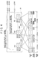
- a functional block diagram of a data transmission apparatus 1 embodying the present invention Upon a demand from an audience terminal 2 for a program, the data transmission apparatus 1 selects, from a plurality of channels sending the requested program, a channel on which a program start time is nearest, and provides the selected channel to the audience terminal 2.
- a program library 3 of the data transmission apparatus 1 serves as a data providing means, stores all program data that can be provided to the audience terminal 2, and outputs k types of programs from k output channels simultaneously.
- a matrix switcher 4 is switching means for capturing the k pieces of data coming from the program library 3 and selects a given number of pieces of data to output the selected pieces of data from m selected channels respectively.
- Formatters 6a through 6m adds an ID corresponding to the audience terminal 2 to the data coming from the channels of the data transmitters 5a through 5m and convert the data to a format of a data exchanger 7.
- the data exchanger 7 transfers data with the audience terminal 2.
- a schedule controller 8 receives an instruction such as a program request of the audience terminal 2 from the data exchanger 7 to control each portion associated with program data transmission.
- a program set controller 9 controls, based on the instruction from the schedule controller 8, the program library 3 and the matrix switcher 4 to send a requested program to the data transmitters 5a through 5m.
- a program transmission controller 10 controls the matrix switcher 4, the data transmitters 5a through 5m, the formatters 6a through 6m, and the data exchanger 7 to send the program data to the plurality of channels.
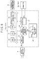
- each of the data transmitters 5a through 5m receives the instruction from the program transmission controller 10 via an external control interface 22 and, based on a program stored in a RAM 23, transfers data with a RAM 24 to make an input interface 25, a mass storage interface and buffer memory 26, and an output interface 27 perform a variety of instructions.
- the input interface 25 receives the program data sent from the matrix switcher 4 to supply the received program data to the mass storage interface and buffer memory 26.
- the program data is stored in the mass storage 28 that provides data storage means such as a disk recording apparatus for example.
- the mass storage 28 stores the program data in a manner as described below so that the program data are transmitted to the plurality of channels 1 through 12 starting with the head of the program data simultaneously or by shifting by a certain amount.
- the program data SA (hereinafter referred as data SA) supplied from the matrix switcher 4 are rearranged in the mass storage 28 according to a certain procedure to provide data SB.
- Fig. 3 shows a case in which the data SA for two hours are recorded in the mass storage 28 with a data read/write rate being 40 megabits/second, a maximum access time (a maximum seek time + a maximum rotational delay time) being 0.25 second, and a program data amount for one second being 3.2 Megabits for example.
- the maximum number of channels is obtained from the equation (1) below. Since n ⁇ 12.49 in the above-mentioned case, the maximum number of channels is 12.
- each of the blocks A through L contains the data for 10 minutes.
- Each of the blocks A through L is divided by 2400 into 0 through 2399.
- the data SA divided into A0 through L2399 (12 ⁇ 2400) are rearranged so that the same numbers in each of the blocks A through L are continuous in the ascending order to provide the data SB as shown in Fig. 3.
- the data are rearranged when the data are stored in the mass storage 28, it will be apparent for those skilled in the art that the data stored in the program library 3 are arranged beforehand in the same arrangement of the data SB of Fig. 3.
- the data SB thus arranged and stored are read from the start sequentially to be sequentially stored in data output means in the mass storage interface and buffer memory 26, in this example, buffer memories 26A, 26A', 26B, 26B', ..., 26L, 26L', as shown in Fig. 4.
- the buffer memories 26A through 26L' are provided on each of channels 1 through 12 in the number of two. It should be noted that the number of buffer memories may be at least equal to the number of channels.
- the first data A0 is stored in the buffer memory 26A and the next data B0 is stored in the buffer memory 26B.
- the data L0 is stored in the buffer memory 26L.
- the 13th data A1 is read to be stored in the second buffer memory 26A' corresponding to the channel 1.
- the read data A0 through L2399 are sequentially stored in 24 butter memories 26A through 26L'.
- the data A0 through L2399 stored in the butter memories 26A through 26L' are read as required to be transmitted from the channels 1 through 12.
- the data SB stored in the mass storage 28 are read at 40 megabits/second. Namely, the whole data SB are read in 9 minutes and 36 seconds, so that each of the data A0, B0, ..., L2399 is read in 0.02 second to be stored in the buffer memories 26A through 26L' respectively. From the buffer memories 26A through 26L', each of the data A0 through L2399 is read at a normal rate (3.2 megabits/second).
- the blocks A (A0 through A2399), B (B0 through B2399), ..., L (L0 through L2399) are transmitted to the channels 1 through 12 respectively, each of the blocks shifted from the other by one block as shown in Fig. 5. Each of the blocks A through L is transmitted in 10 minutes.
- the data SB in the mass storage 28 are read once, the data SB are read again at 40 megabits/second to be stored in the buffer memories 26A through 26L' from which to be transmitted at the normal rate.
- the block B is stored in the first buffer memory 28A of the channel 1, the following blocks being stored in the like manner in the buffer memories 26B through 26L' respectively, shifted by one block.
- the block C is stored in the first buffer memory 26A of the channel 1.
- the block D is stored in the buffer memory 26A.
- the data stored in the mass storage 28 are read by shifting the data blocks by a certain amount in each read operation, so that the data SB in the mass storage 28 may all be transmitted over the channels 1 through 12 simultaneously or by shifting the data by a certain amount over the channels.
- relatively short programs of 10 minutes each for example are recorded in the blocks A through L
- 12 different programs may be transmitted from the channels 1 through 12 simultaneously.
- the program transmission controller 10 controls the formatter 6a through 6m and the data exchanger 7 such that a channel having a program start time nearest an audience request time is selected for transmission.
- each mass storage of each of data transmitters 5'a through 5'm is composed of a multi-head disk unit 29.
- the multi-head disk unit 29 has one recording head and p reproducing heads.
- Use of the multi-head disk unit having p reproducing heads allows to output the same data to the number of channels times p starting from the head of the data simultaneously via an output interface 27 by shifting the data on each channel by a certain amount.
- the same data may be substantially outputted from the output interface 27 on n times p channels starting from the head of the data simultaneously or by shifting the data on each channel by a certain amount.
- the data transmitters 5'a through 5'm may output a program with a time difference of 10/p minutes, while the data transmitters 5a through 5m of Fig. 2 having the mass storage 28 with only one reproducing head may output the program with a time difference of 10 minutes.
- FIG. 7 there is illustrated an operation of the data transmitter 5'a (through 5'm) having p reproducing head, p being equal to 2.
- the head X reads the data SB from its head, while the head Y reads the data SB at a position, with reference to the head X, ahead of one half of an amount of the data recorded on the multi-head disk unit 29. Namely, when the head X is located at the start of A0, the head Y is located at the start of A1200.
- This setup allows the channels 13 through 24 on the head X side to transmit a program five minutes ahead of the channels 1 through 12 respectively.
- the time difference for differential time transmission may be reduced to realize relatively fine services. If a time difference same as that for a single head, there is no need for recording data to the mass storage in a relatively small unit such as 100 sectors, thereby reducing the number of times data are switched during the transmission of a program of the same time as well as the number of seek times returning from the end of the mass storage to the top thereof. Consequently, the present embodiment may be applied to a storage unit having a relatively low read rate.
- an disk array unit 31 of Fig. 9 may be used, the disk array unit being composed of a plurality of mass storage devices 28-1, 28-2, ..., 28-p controlled by a disk array controller 30.
- a data transmitter 5''a to 5''m has the disk array unit 31 consisting of an array of the plurality of mass storage devices 28-1, 28-2, ..., 28-p, the disk array unit being controlled by the disk array controller 30.
- the data SB for one program is smaller than a capacity of one mass storage
- a plurality of programs are stored in the mass storage devices respectively, and remaining portions in the mass storage devices are combined to store yet another program, thereby substantially eliminating a wasted space of the disk array unit 31.
- any one of the mass storage devices is used for parity bits, an error detected in other data may be also recovered.
- the above-mentioned setup enhances the transmission rate and storage capacity of the data transmitters 5'a through 5'm, thereby increasing the number of output channels while reducing the wasted space of the disk array unit 31.
- data may be stored in the mass storage 28 with redundancy and the data is read based on the redundancy for error correction, thereby enhancing system reliability.
- a data transmission apparatus comprising data supply means for storing a plurality of different types of data and sending different types of data to respective different channels simultaneously.
- switching means for outputting data of each channel read from a data library to another selected channel, data storage means for storing data outputted from each selected channel by rearranging the data in a predetermined array, and data output means for outputting the data stored in the data storage means from a plurality of channels simultaneously by shifting the data by a certain amount.
Abstract
Description
- The present invention relates to a data transmission, and provides apparatus which can be applied, though not exclusively, to a video on-demand apparatus for sending data such as image data upon demand by audience.
- In the video on-demand apparatus for providing programs as required by audience, image data including movies and other various types of data are transmitted through a plurality of channels. One of the methods for implementing the video on-demand apparatus is to provide a magnetic-tape reproducing apparatus for each of a plurality of channels and send data for all the channels simultaneously or data for each channel one after another. Alternatively, using random access of such apparatuses as a hard disk unit and an optical disk unit, random access is performed on multiple types of data recorded on a single disk to send each type of data over each channel.
- However, the method in which a magnetic-tape reproducing apparatus is provided on each channel increases the number of magnetic-tape reproducing apparatus, resulting in the costly video on-demand apparatus. Additionally, in this method, a magnetic tape is reproduced repetitively, imposing a hazard of damage thereof. Further, during time in which a magnetic tape is being rewound, the data transmission service is disabled. On the other hand, the method in which a random access disk apparatus is used requires to frequently repeat random access operations to send data for multiple channels. Consequently, if there are too many channels, the access time increases accordingly with the data providing time decreased, requiring to decrease the number of channels.
- According to one aspect of the invention there is provided a data transmission method comprising the steps of: dividing input data of length T into N number of pieces of data providing a first major block through an N-th major block; dividing each of the first major block through N-th major block into R minor blocks composed of a first minor block through an R-th minor block; rearranging the minor blocks of the major blocks so that the first minor block of the first major block is followed by the first minor block of the second major block and so on until followed by the first minor block of the N-th major block providing a rearranged major block, the rearranged major block being following by another rearranged major block starting with the second minor block of the first major block followed by the second minor block of the second major block and so on until followed by the second minor block of the N-th major block, the another rearranged major block being followed by still another major block with its minor blocks rearranged in the similar order, and so on until followed by the last major block starting with the R-th minor block of the first major block and ending with the R-th minor block of the N-th major block; recording the rearranged data on a recording medium; reproducing reproduction data from the recording medium; recording the reproduction data in a plurality of memories a plurality of times continuously so that the minor blocks in one of the major blocks of the reproduction data are stored in one of the memories in one storage operation; and reading the reproduction data in parallel from the plurality of memories a plurality of times continuously.
- Respective further aspects of the invention are set forth in
claims - Embodiments of the present invention solve one or more of the above-mentioned problems by providing a data transmission apparatus of a relatively low cost and accommodating relatively a large number of channels.
- In embodiments of the present invention, there is no need for using a plurality of reproducing units as with the previous constitution of using a magnetic tape, thus resulting in a simpler construction and a reduced cost. Additionally, there is no need for random access as with the previous constitution using a magnetic tape, thus resulting in a longer data read time, which in turn increases the number of channels.
- Embodiments of the invention will now be described, by way of example, with reference to the accompanying drawings in which:
- Fig. 1 is a block diagram illustrating a data transmission apparatus of a first preferred embodiment of the invention;
- Fig. 2 is a block diagram illustrating one of
data transmitters 5a through 5m of the embodiment of Fig. 1; - Fig. 3 is a schematic diagram illustrating data SB stored in a mass storage;
- Fig. 4 is a schematic diagram illustrating a data read operation with the mass storage;
- Fig. 5 is a schematic diagram illustrating output data of one of the
data transmitters 5a through 5m; - Fig. 6 is a detail block diagram illustrating a data transmission apparatus of a second preferred embodiment of the invention;
- Fig. 7 is a schematic diagram illustrating output data of the data transmission apparatus of Fig. 6;
- Fig. 8 is a schematic diagram illustrating another output data of the data transmission apparatus of Fig. 6; and
- Fig. 9 is a block diagram illustrating another data transmission apparatus applicable to the data transmission apparatus of Fig. 1.
- A first embodiment of the invention will be described with reference to Figs. 1 through 5 of the accompanying drawing.
- Referring to Fig. 1, there is shown a functional block diagram of a
data transmission apparatus 1 embodying the present invention. Upon a demand from anaudience terminal 2 for a program, thedata transmission apparatus 1 selects, from a plurality of channels sending the requested program, a channel on which a program start time is nearest, and provides the selected channel to theaudience terminal 2. Aprogram library 3 of thedata transmission apparatus 1 serves as a data providing means, stores all program data that can be provided to theaudience terminal 2, and outputs k types of programs from k output channels simultaneously. Amatrix switcher 4 is switching means for capturing the k pieces of data coming from theprogram library 3 and selects a given number of pieces of data to output the selected pieces of data from m selected channels respectively.Data transmitters 5a through 5m provided for the m channels respectively have n output channels (for example, n = 12) each and output the same data supplied from thematrix switcher 4 to the channels simultaneously starting with the head of the data or by shifting the data by a certain amount.Formatters 6a through 6m adds an ID corresponding to theaudience terminal 2 to the data coming from the channels of thedata transmitters 5a through 5m and convert the data to a format of adata exchanger 7. The data exchanger 7 transfers data with theaudience terminal 2. - A
schedule controller 8 receives an instruction such as a program request of theaudience terminal 2 from thedata exchanger 7 to control each portion associated with program data transmission. A program setcontroller 9 controls, based on the instruction from theschedule controller 8, theprogram library 3 and thematrix switcher 4 to send a requested program to thedata transmitters 5a through 5m. Upon receiving the instruction from theschedule controller 8, aprogram transmission controller 10 controls thematrix switcher 4, thedata transmitters 5a through 5m, theformatters 6a through 6m, and thedata exchanger 7 to send the program data to the plurality of channels. - Referring to Fig. 2, there is shown a configuration of each of the
data transmitters 5a through 5m. A CPU (Central Processing Unit) 21 each of thedata transmitters 5a through 5m receives the instruction from theprogram transmission controller 10 via anexternal control interface 22 and, based on a program stored in aRAM 23, transfers data with aRAM 24 to make aninput interface 25, a mass storage interface andbuffer memory 26, and anoutput interface 27 perform a variety of instructions. Theinput interface 25 receives the program data sent from thematrix switcher 4 to supply the received program data to the mass storage interface andbuffer memory 26. Then, the program data is stored in themass storage 28 that provides data storage means such as a disk recording apparatus for example. Themass storage 28 stores the program data in a manner as described below so that the program data are transmitted to the plurality ofchannels 1 through 12 starting with the head of the program data simultaneously or by shifting by a certain amount. - Namely, as shown in Fig. 3, the program data SA (hereinafter referred as data SA) supplied from the
matrix switcher 4 are rearranged in themass storage 28 according to a certain procedure to provide data SB. Fig. 3 shows a case in which the data SA for two hours are recorded in themass storage 28 with a data read/write rate being 40 megabits/second, a maximum access time (a maximum seek time + a maximum rotational delay time) being 0.25 second, and a program data amount for one second being 3.2 Megabits for example. In the above-mentioned case, the maximum number of channels is obtained from the equation (1) below. Since n ≦ 12.49 in the above-mentioned case, the maximum number of channels is 12.

where n (D/r + ta) = a time (in seconds) for reading the mass storage 28 n times;
D/d = a time (in seconds) for transmitting a program from themass storage 28;
D = a program data amount (in Megabits);
r = the read/write rate (in Megabits/second) of themass storage 28;
ta = the maximum access time (in seconds) of themass storage 28; and
d = the data transmission rate (Megabits/second) of thetransmitter 5. - In the above-mentioned case, a same program is transmitted to the 12
channels 1 through 12 simultaneously by shifting the program data by a certain amount, so that the data SA is first divided into 12 blocks A through L as shown in Fig. 3. Consequently, each of the blocks A through L contains the data for 10 minutes. Each of the blocks A through L is divided by 2400 into 0 through 2399. A data amount of each of the divided data blocks A0, A1, ... L2399 is (3.2 megabits × 60" × 120')/(12 × 2400) = 0.8 megabit. Given a minimum read/write unit of themass storage 28 of one sector (= 1 kilobyte = 8 kilobits), the data amount of each of the divided data blocks A0 through L2399 is 0.8 megabits/8 kilobits = 100 sectors. - Thus, the data SA divided into A0 through L2399 (12 × 2400) are rearranged so that the same numbers in each of the blocks A through L are continuous in the ascending order to provide the data SB as shown in Fig. 3. Although, in the above-mentioned example, the data are rearranged when the data are stored in the
mass storage 28, it will be apparent for those skilled in the art that the data stored in theprogram library 3 are arranged beforehand in the same arrangement of the data SB of Fig. 3. - The data SB thus arranged and stored are read from the start sequentially to be sequentially stored in data output means in the mass storage interface and
buffer memory 26, in this example,buffer memories buffer memories 26A through 26L' are provided on each ofchannels 1 through 12 in the number of two. It should be noted that the number of buffer memories may be at least equal to the number of channels. The first data A0 is stored in thebuffer memory 26A and the next data B0 is stored in thebuffer memory 26B. Likewise, the data L0 is stored in thebuffer memory 26L. Then, the 13th data A1 is read to be stored in thesecond buffer memory 26A' corresponding to thechannel 1. Thus, the read data A0 through L2399 are sequentially stored in 24butter memories 26A through 26L'. The data A0 through L2399 stored in thebutter memories 26A through 26L' are read as required to be transmitted from thechannels 1 through 12. - At this moment, the data SB stored in the
mass storage 28 are read at 40 megabits/second. Namely, the whole data SB are read in 9 minutes and 36 seconds, so that each of the data A0, B0, ..., L2399 is read in 0.02 second to be stored in thebuffer memories 26A through 26L' respectively. From thebuffer memories 26A through 26L', each of the data A0 through L2399 is read at a normal rate (3.2 megabits/second). The blocks A (A0 through A2399), B (B0 through B2399), ..., L (L0 through L2399) are transmitted to thechannels 1 through 12 respectively, each of the blocks shifted from the other by one block as shown in Fig. 5. Each of the blocks A through L is transmitted in 10 minutes. When the data SB in themass storage 28 are read once, the data SB are read again at 40 megabits/second to be stored in thebuffer memories 26A through 26L' from which to be transmitted at the normal rate. This time, however, the block B is stored in the first buffer memory 28A of thechannel 1, the following blocks being stored in the like manner in thebuffer memories 26B through 26L' respectively, shifted by one block. In the third time, the block C is stored in thefirst buffer memory 26A of thechannel 1. In the fourth time, the block D is stored in thebuffer memory 26A. - As descried above, the data stored in the
mass storage 28 are read by shifting the data blocks by a certain amount in each read operation, so that the data SB in themass storage 28 may all be transmitted over thechannels 1 through 12 simultaneously or by shifting the data by a certain amount over the channels. If relatively short programs of 10 minutes each for example are recorded in the blocks A through L, 12 different programs may be transmitted from thechannels 1 through 12 simultaneously. Alternatively, if a movie of 120 minutes is recorded for example, the same movie is transmitted from thechannels 1 through 12 with a delay of 10 minutes, each time from the start of the movie, so that audience may always view the program from the beginning by waiting at least 10 minutes. In this case, theprogram transmission controller 10 controls theformatter 6a through 6m and thedata exchanger 7 such that a channel having a program start time nearest an audience request time is selected for transmission. - In what follows, a second preferred embodiment of the present invention will be described. Referring to Fig. 6, the second preferred embodiment is generally the same as the first preferred embodiment except that each mass storage of each of data transmitters 5'a through 5'm is composed of a
multi-head disk unit 29. Themulti-head disk unit 29 has one recording head and p reproducing heads. Use of the multi-head disk unit having p reproducing heads allows to output the same data to the number of channels times p starting from the head of the data simultaneously via anoutput interface 27 by shifting the data on each channel by a certain amount. As a result, the same data may be substantially outputted from theoutput interface 27 on n times p channels starting from the head of the data simultaneously or by shifting the data on each channel by a certain amount. - Consequently, the data transmitters 5'a through 5'm may output a program with a time difference of 10/p minutes, while the
data transmitters 5a through 5m of Fig. 2 having themass storage 28 with only one reproducing head may output the program with a time difference of 10 minutes. - For example, referring to Fig. 7, there is illustrated an operation of the data transmitter 5'a (through 5'm) having p reproducing head, p being equal to 2. The two heads are represented by a head X and a head Y. Since the number of program transmitting channels n is 12 as mentioned earlier, the substantial number of channels is 12 × 2 = 24. It should be noted that data reproduced through the head X is supplied to the
channels 1 through 12 and data reproduced through the head Y is supplied to thechannels 13 to 24. - In this case, the head X reads the data SB from its head, while the head Y reads the data SB at a position, with reference to the head X, ahead of one half of an amount of the data recorded on the
multi-head disk unit 29. Namely, when the head X is located at the start of A0, the head Y is located at the start of A1200. This setup allows thechannels 13 through 24 on the head X side to transmit a program five minutes ahead of thechannels 1 through 12 respectively. - If short programs of five minutes to data A0 through A1199, A1200 through A2399, B0 through B1199, ..., L1200 through L2399 respectively, 24 different programs may be transmitted simultaneously.
- In the
data transmitters 5a through 5m having themass storage 28 with only one reproducing head of Fig. 2, the number of data switching times for a program of 120 minutes for example through the reproducing head is 2400 × 12 = 28800 and the number of seek operations from end of the mass storage back to its top is 12. If the same time difference as with the single head of Fig. 2 is allowed for the data transmitter having themulti-head disk unit 29 with p reproducing heads, the above-mentioned number of data switching times and number of seek operations are both reduced to 1/p. - For example, as shown in Fig. 8, the data on a 200 sector basis on the multi-head disk unit, namely A0, B0, ..., F0, A1, B1, ..., A2399, B2399, ..., F2399 are reproduced through the head X and the head Y with p = 2, and the reproduced data are supplied to the even-number channels and the odd-number channels respectively for output with a time difference of 10 minutes. In this case, the number of times the reproducing heads are switched for a program of 120 minutes is only 2400 × 6 = 14400, and the number of seek times is only 6.
- As described above, in the
data transmission system 1 having the above-mentioned data transmitters 5'a through 5'm, the time difference for differential time transmission may be reduced to realize relatively fine services. If a time difference same as that for a single head, there is no need for recording data to the mass storage in a relatively small unit such as 100 sectors, thereby reducing the number of times data are switched during the transmission of a program of the same time as well as the number of seek times returning from the end of the mass storage to the top thereof. Consequently, the present embodiment may be applied to a storage unit having a relatively low read rate. - It will be apparent for those skilled in the art that the data transmitter associated with the present invention is not limited to the above-mentioned preferred embodiment. For example, instead of the multi-head disk unit, an
disk array unit 31 of Fig. 9 may be used, the disk array unit being composed of a plurality of mass storage devices 28-1, 28-2, ..., 28-p controlled by adisk array controller 30. - Namely, referring to Fig. 9, a data transmitter 5''a to 5''m has the
disk array unit 31 consisting of an array of the plurality of mass storage devices 28-1, 28-2, ..., 28-p, the disk array unit being controlled by thedisk array controller 30. In this setup, if the data SB for one program is smaller than a capacity of one mass storage, a plurality of programs are stored in the mass storage devices respectively, and remaining portions in the mass storage devices are combined to store yet another program, thereby substantially eliminating a wasted space of thedisk array unit 31. Further, if any one of the mass storage devices is used for parity bits, an error detected in other data may be also recovered. Additionally, the above-mentioned setup enhances the transmission rate and storage capacity of the data transmitters 5'a through 5'm, thereby increasing the number of output channels while reducing the wasted space of thedisk array unit 31. - Further, in the
data transmission apparatus 1, data may be stored in themass storage 28 with redundancy and the data is read based on the redundancy for error correction, thereby enhancing system reliability. - As mentioned above and according embodiments of the invention, there is provided a data transmission apparatus comprising data supply means for storing a plurality of different types of data and sending different types of data to respective different channels simultaneously. switching means for outputting data of each channel read from a data library to another selected channel, data storage means for storing data outputted from each selected channel by rearranging the data in a predetermined array, and data output means for outputting the data stored in the data storage means from a plurality of channels simultaneously by shifting the data by a certain amount.
- Consequently, in embodiments of the present invention, there is no need for using a plurality of reproducing units as with the previous constitution of using a magnetic tape, thus resulting in a simpler construction and a reduced cost. Additionally, there is no need for random access as with the previous constitution using a magnetic tape, thus resulting in a longer data read time, which in turn increases the number of channels.
- While preferred embodiments of the present invention have been described, such description is for illustrative purposes only, and it is to be understood that changes and variations may be made without departing from the scope of the appended claims.
Claims (17)
- A data transmission method comprising the steps of:
dividing input data of length T into N number of pieces of data providing a first major block through an N-th major block;
dividing each of said first major block through N-th major block into R minor blocks composed of a first minor block through an R-th minor block;
rearranging said minor blocks of said major blocks so that the first minor block of said first major block is followed by the first minor block of the second major block and so on until followed by the first minor block of the N-th major block providing a rearranged major block, said rearranged major block being following by another rearranged major block starting with the second minor block of the first major block followed by the second minor block of the second major block and so on until followed by the second minor block of the N-th major block, said another rearranged major block being followed by still another major block with its minor blocks rearranged in the similar order, and so on until followed by the last major block starting with the R-th minor block of the first major block and ending with the R-th minor block of the N-th major block;
recording the rearranged data on a recording medium;
reproducing reproduction data from said recording medium;
recording said reproduction data in a plurality or memories a plurality of times continuously so that said minor blocks in one of said major blocks of said reproduction data are stored in one of said memories in one storage operation; and
reading said reproduction data in parallel from said plurality of memories a plurality of times continuously. - A data transmission method as defined in claim 1, wherein said reproduction data is reproduced from said recording medium and stored in said plurality of memories at a rate higher than N times a rate at which said reproduction data is read from said plurality of memories.
- A data transmission method as defined in claim 1, wherein the number of said plurality of memories is at least N.
- A data transmission method as defined in claim 1, wherein, in the step of storing said reproduction data in said plurality of memories, said reproduction data is stored in said plurality of memories so that the memory in which the reproduction data of n-th (n = 1 to N) major block is stored stores reproduction data of an n + 1th major block in a next storage operation.
- A data transmission apparatus comprising:
recording and reproducing means for recording and reproducing input data on a recording medium, said input data being divided into N major blocks composed of a first major block through an N-th major block, each of said major blocks being further divided into R minor blocks composed of a first minor block through an R-th minor block, the resultant data blocks being stored and reproduced on said recording medium in an order that the first minor block of said first major block is followed by the first minor block of the second major block and so on until followed by the first minor block of the N-th major block providing a rearranged major block, said rearranged major block being following by another rearranged major block starting with the second minor block of the first major block followed by the second minor block of the second major block and so on until followed by the second minor block of the N-th major block, said another rearranged major block being followed by still another major block with its minor blocks rearranged in the similar manner, and so on until followed by the last major block starting with the R-th minor block of the first major block and ending with the R-th minor block of the N-th major block; and
a plurality of memories for storing reproduction data reproduced from said recording medium by said recording and reproducing means a plurality of times continuously so that said minor blocks in one of said major blocks of said reproduction data are stored in one of said plurality of memories in a one storage operation, said reproduction data being read plurality of times in parallel from said memory. - A data transmission apparatus as defined in claim 5, wherein said reproduction data is reproduced from said recording medium and stored in said plurality of memories at a rate higher than N times a rate at which said reproduction data is read from said plurality of memories.
- A data transmission apparatus as defined in claim 5, wherein the number of said plurality of memories is at least N.
- A data transmission apparatus as defined in claim 5, wherein the memory in which reproduction data of an n-th (n = 1 to N) major block is stored stores reproduction data of an n + 1th major block in a next storage operation.
- A data transmission apparatus as defined in claim 5, wherein said recording and reproducing apparatus having a plurality of P reproducing heads, said plurality of P reproducing heads reproduce said reproduction data on said recording medium at respective different locations.
- A data transmission apparatus comprising:
supplying means for storing a plurality of types of data and supplying said plurality of types of data to each of a plurality of channels;
switching means for selectively outputting said plurality types of data supplied from said supplying means to a plurality of channels;
a plurality of data transmitting means each having recording and reproducing means for dividing data entered from said switching means into N major blocks composed of a first major block through an N-th major block, further dividing each of said major blocks into R minor blocks composed of a first minor block through an R-th minor block, and recording and reproducing, on a recording medium, the resultant data blocks in an order that the first minor block of said first major block is followed by the first minor block of the second major block and so on until followed by the first minor block of the N-th major block providing a rearranged major block, said rearranged major block being following by another rearranged major block starting with the second minor block of the first major block followed by the second minor block of the second major block and so on until followed by the second minor block of the N-th major block, said another rearranged major block being followed by still another major block with its minor blocks rearranged in the similar order, and so on until followed by the last major block starting with the R-th minor block of the first major block and ending with the R-th minor block of the N-th major block, said plurality of data transmitting means each also having a plurality of memories for storing, a plurality of times continuously, data reproduced from said recording medium by said recording and reproducing means such that the minor blocks of one major block of the reproduced data are stored in one of said plurality of memories in a single storage operation, the stored data being outputted to a plurality of output channels in parallel a plurality of times continuously; and
control means for performing control, according to a transmission request coming from audience, such that the requested data is transmitted at a time nearest a requested time from the output channels of said data transmitting means to the audience. - A data transmission apparatus for reproducing data from a recording medium recorded periodically with a plurality of time-divided pieces of data of N channels, N being an integer of 2 or higher, the reproduced data of each of said N channels being distributed to said N channels for transmission as the data of said N channels, said data transmission apparatus having P reproducing heads, P being an integer of 2 or higher, said data time-shifted by reproducing positions of said P reproducing heads based on output data from said P reproducing heads being transmitted from said N channels.
- A data transmission apparatus as defined in claim 11, wherein the plurality of pieces of data of said N channels are the same in content but shifted in time.
- A data transmission apparatus as defined in claim 12, wherein the time shift between said N channels T/N, T being a length of all the data.
- A data transmission system comprising:
a data supplying apparatus for simultaneously supplying a plurality of pieces of data to a plurality of channels respectively;
a switching apparatus for outputting the plurality of pieces of data supplied to said plurality of channels to the different channels respectively; and
a data transmission apparatus for receiving said plurality of pieces of data from said switching apparatus. - A data transmission apparatus comprising:
data supplying means for storing a plurality of types of data and simultaneously transmitting said plurality of types of data to a plurality of selected channels respectively;
switching means for outputting said plurality of types of data outputted from said data supplying means to the selected different channels respectively;
data storage means for storing the data outputted from said selected channels after rearranging said data in a predetermined order; and
data outputting means for outputting the data stored in said data storage means from the plurality of channels after shifting said data by a certain amount. - A data transmission apparatus comprising:
data supplying means for storing a plurality of types of data and simultaneously transmitting said plurality of types of data to a plurality of selected channels respectively;
switching means for outputting said plurality of types of data outputted from said data supplying means to the selected different channels respectively;
data storage means for storing the data outputted from said selected channels after rearranging said data in a predetermined order; and
data simultaneous transmitting means for simultaneously outputting the data stored in said data storage means from the plurality of channels. - A data transmission apparatus as defined in claim 15 or 16, wherein said data storage means is provided in plurality.
Priority Applications (1)
| Application Number | Priority Date | Filing Date | Title |
|---|---|---|---|
| EP99200302A EP0935394A2 (en) | 1994-05-26 | 1995-05-25 | Transmission of time-shifted data to a plurality of channels |
Applications Claiming Priority (3)
| Application Number | Priority Date | Filing Date | Title |
|---|---|---|---|
| JP11294094 | 1994-05-26 | ||
| JP112940/94 | 1994-05-26 | ||
| JP11294094 | 1994-05-26 |
Related Child Applications (1)
| Application Number | Title | Priority Date | Filing Date |
|---|---|---|---|
| EP99200302A Division EP0935394A2 (en) | 1994-05-26 | 1995-05-25 | Transmission of time-shifted data to a plurality of channels |
Publications (2)
| Publication Number | Publication Date |
|---|---|
| EP0686908A1 true EP0686908A1 (en) | 1995-12-13 |
| EP0686908B1 EP0686908B1 (en) | 1999-11-24 |
Family
ID=14599315
Family Applications (2)
| Application Number | Title | Priority Date | Filing Date |
|---|---|---|---|
| EP95303548A Expired - Lifetime EP0686908B1 (en) | 1994-05-26 | 1995-05-25 | Server for video on demand system |
| EP99200302A Withdrawn EP0935394A2 (en) | 1994-05-26 | 1995-05-25 | Transmission of time-shifted data to a plurality of channels |
Family Applications After (1)
| Application Number | Title | Priority Date | Filing Date |
|---|---|---|---|
| EP99200302A Withdrawn EP0935394A2 (en) | 1994-05-26 | 1995-05-25 | Transmission of time-shifted data to a plurality of channels |
Country Status (4)
| Country | Link |
|---|---|
| US (2) | US5757415A (en) |
| EP (2) | EP0686908B1 (en) |
| KR (1) | KR950035195A (en) |
| DE (1) | DE69513446T2 (en) |
Cited By (4)
| Publication number | Priority date | Publication date | Assignee | Title |
|---|---|---|---|---|
| EP0731468A2 (en) * | 1995-03-06 | 1996-09-11 | Sony Corporation | Video data recording and reproducing |
| EP0766473A2 (en) * | 1995-09-29 | 1997-04-02 | Hewlett-Packard Company | Digital layout method suitable for near video on demand system |
| WO1997013369A1 (en) * | 1995-09-29 | 1997-04-10 | Philips Electronics N.V. | Method and system for storing and reading data blocks for a number of user groups |
| US6233735B1 (en) | 1995-11-13 | 2001-05-15 | Sony Corporation | Near video-on-demand system and broadcasting method therefor |
Families Citing this family (53)
| Publication number | Priority date | Publication date | Assignee | Title |
|---|---|---|---|---|
| US5757415A (en) * | 1994-05-26 | 1998-05-26 | Sony Corporation | On-demand data transmission by dividing input data into blocks and each block into sub-blocks such that the sub-blocks are re-arranged for storage to data storage means |
| US5801787A (en) | 1996-06-14 | 1998-09-01 | Starsight Telecast, Inc. | Television schedule system and method of operation for multiple program occurrences |
| US6173330B1 (en) * | 1996-09-17 | 2001-01-09 | Motorola, Inc. | Delivery and acquisition of data segments with optimized inter-arrival time |
| JP2000515706A (en) * | 1997-05-26 | 2000-11-21 | コーニンクレッカ フィリップス エレクトロニクス エヌ ヴィ | A system that retrieves data from a stream server |
| US6415373B1 (en) | 1997-12-24 | 2002-07-02 | Avid Technology, Inc. | Computer system and process for transferring multiple high bandwidth streams of data between multiple storage units and multiple applications in a scalable and reliable manner |
| US6374336B1 (en) * | 1997-12-24 | 2002-04-16 | Avid Technology, Inc. | Computer system and process for transferring multiple high bandwidth streams of data between multiple storage units and multiple applications in a scalable and reliable manner |
| US6157949A (en) * | 1998-05-28 | 2000-12-05 | Industrial Technology Research Institute | Data placement on direct access devices for media servers with cyclic re-broadcast capability |
| CN1867068A (en) | 1998-07-14 | 2006-11-22 | 联合视频制品公司 | Client-server based interactive television program guide system with remote server recording |
| US7068729B2 (en) * | 2001-12-21 | 2006-06-27 | Digital Fountain, Inc. | Multi-stage code generator and decoder for communication systems |
| US6307487B1 (en) | 1998-09-23 | 2001-10-23 | Digital Fountain, Inc. | Information additive code generator and decoder for communication systems |
| US6486897B1 (en) * | 1998-09-29 | 2002-11-26 | Apple Computer, Inc. | Multi-repository display system using separate presentation, adaptation and access layers |
| US20020056127A1 (en) * | 2000-09-15 | 2002-05-09 | Israel Amir | Video, audio and data on demand |
| KR101399240B1 (en) | 2000-10-11 | 2014-06-02 | 유나이티드 비디오 프로퍼티즈, 인크. | Systems and methods for delivering media content |
| CA2428829A1 (en) * | 2000-11-10 | 2002-05-16 | Prediwave Corporation | Decreased idle time and constant bandwidth data-on-demand broadcast delivery matrices |
| US7240358B2 (en) * | 2000-12-08 | 2007-07-03 | Digital Fountain, Inc. | Methods and apparatus for scheduling, serving, receiving media-on demand for clients, servers arranged according to constraints on resources |
| US7143179B2 (en) * | 2001-05-24 | 2006-11-28 | Yuri Yaport | Method and system for parallel data transmission on demand to an unlimited number of clients without acknowledgment and on the basis of constant data availability |
| US7110421B2 (en) * | 2001-11-28 | 2006-09-19 | Sony Corporation | System and method for transmitting information over multiple channels |
| US9240810B2 (en) | 2002-06-11 | 2016-01-19 | Digital Fountain, Inc. | Systems and processes for decoding chain reaction codes through inactivation |
| EP2348640B1 (en) | 2002-10-05 | 2020-07-15 | QUALCOMM Incorporated | Systematic encoding of chain reaction codes |
| DE10253918A1 (en) * | 2002-11-19 | 2004-06-17 | Infineon Technologies Ag | Storage system, in particular for network broadcasting applications such as video / audio applications, and method for operating a storage system |
| US7493646B2 (en) | 2003-01-30 | 2009-02-17 | United Video Properties, Inc. | Interactive television systems with digital video recording and adjustable reminders |
| US8832758B2 (en) * | 2003-03-17 | 2014-09-09 | Qwest Communications International Inc. | Methods and systems for providing video on demand |
| US7139960B2 (en) | 2003-10-06 | 2006-11-21 | Digital Fountain, Inc. | Error-correcting multi-stage code generator and decoder for communication systems having single transmitters or multiple transmitters |
| WO2005112250A2 (en) | 2004-05-07 | 2005-11-24 | Digital Fountain, Inc. | File download and streaming system |
| US9136983B2 (en) | 2006-02-13 | 2015-09-15 | Digital Fountain, Inc. | Streaming and buffering using variable FEC overhead and protection periods |
| US9270414B2 (en) * | 2006-02-21 | 2016-02-23 | Digital Fountain, Inc. | Multiple-field based code generator and decoder for communications systems |
| WO2007134196A2 (en) | 2006-05-10 | 2007-11-22 | Digital Fountain, Inc. | Code generator and decoder using hybrid codes |
| US9386064B2 (en) | 2006-06-09 | 2016-07-05 | Qualcomm Incorporated | Enhanced block-request streaming using URL templates and construction rules |
| US9178535B2 (en) * | 2006-06-09 | 2015-11-03 | Digital Fountain, Inc. | Dynamic stream interleaving and sub-stream based delivery |
| US9419749B2 (en) | 2009-08-19 | 2016-08-16 | Qualcomm Incorporated | Methods and apparatus employing FEC codes with permanent inactivation of symbols for encoding and decoding processes |
| US9209934B2 (en) | 2006-06-09 | 2015-12-08 | Qualcomm Incorporated | Enhanced block-request streaming using cooperative parallel HTTP and forward error correction |
| US9432433B2 (en) | 2006-06-09 | 2016-08-30 | Qualcomm Incorporated | Enhanced block-request streaming system using signaling or block creation |
| US9380096B2 (en) | 2006-06-09 | 2016-06-28 | Qualcomm Incorporated | Enhanced block-request streaming system for handling low-latency streaming |
| US20080205229A1 (en) * | 2007-02-26 | 2008-08-28 | Yung-Chih Li | Method of identifying optical disc |
| CN101802797B (en) * | 2007-09-12 | 2013-07-17 | 数字方敦股份有限公司 | Generating and communicating source identification information to enable reliable communications |
| US8510370B2 (en) * | 2008-02-26 | 2013-08-13 | Avid Technology, Inc. | Array-based distributed storage system with parity |
| US10063934B2 (en) | 2008-11-25 | 2018-08-28 | Rovi Technologies Corporation | Reducing unicast session duration with restart TV |
| US9281847B2 (en) * | 2009-02-27 | 2016-03-08 | Qualcomm Incorporated | Mobile reception of digital video broadcasting—terrestrial services |
| US9288010B2 (en) | 2009-08-19 | 2016-03-15 | Qualcomm Incorporated | Universal file delivery methods for providing unequal error protection and bundled file delivery services |
| US9917874B2 (en) | 2009-09-22 | 2018-03-13 | Qualcomm Incorporated | Enhanced block-request streaming using block partitioning or request controls for improved client-side handling |
| US20110096828A1 (en) * | 2009-09-22 | 2011-04-28 | Qualcomm Incorporated | Enhanced block-request streaming using scalable encoding |
| US9225961B2 (en) | 2010-05-13 | 2015-12-29 | Qualcomm Incorporated | Frame packing for asymmetric stereo video |
| US8918533B2 (en) | 2010-07-13 | 2014-12-23 | Qualcomm Incorporated | Video switching for streaming video data |
| US9185439B2 (en) | 2010-07-15 | 2015-11-10 | Qualcomm Incorporated | Signaling data for multiplexing video components |
| US9596447B2 (en) | 2010-07-21 | 2017-03-14 | Qualcomm Incorporated | Providing frame packing type information for video coding |
| US9456015B2 (en) | 2010-08-10 | 2016-09-27 | Qualcomm Incorporated | Representation groups for network streaming of coded multimedia data |
| US9270299B2 (en) | 2011-02-11 | 2016-02-23 | Qualcomm Incorporated | Encoding and decoding using elastic codes with flexible source block mapping |
| US8958375B2 (en) | 2011-02-11 | 2015-02-17 | Qualcomm Incorporated | Framing for an improved radio link protocol including FEC |
| JP5234374B2 (en) * | 2011-03-02 | 2013-07-10 | 日本電気株式会社 | Differential signal transmission circuit, disk array controller, and differential signal transmission cable |
| US9253233B2 (en) | 2011-08-31 | 2016-02-02 | Qualcomm Incorporated | Switch signaling methods providing improved switching between representations for adaptive HTTP streaming |
| US9843844B2 (en) | 2011-10-05 | 2017-12-12 | Qualcomm Incorporated | Network streaming of media data |
| US8805418B2 (en) | 2011-12-23 | 2014-08-12 | United Video Properties, Inc. | Methods and systems for performing actions based on location-based rules |
| US9294226B2 (en) | 2012-03-26 | 2016-03-22 | Qualcomm Incorporated | Universal object delivery and template-based file delivery |
Citations (2)
| Publication number | Priority date | Publication date | Assignee | Title |
|---|---|---|---|---|
| US4949187A (en) * | 1988-12-16 | 1990-08-14 | Cohen Jason M | Video communications system having a remotely controlled central source of video and audio data |
| JPH0541858A (en) * | 1991-05-24 | 1993-02-19 | Matsushita Electric Ind Co Ltd | Wire broadcast system |
Family Cites Families (4)
| Publication number | Priority date | Publication date | Assignee | Title |
|---|---|---|---|---|
| US5442390A (en) * | 1993-07-07 | 1995-08-15 | Digital Equipment Corporation | Video on demand with memory accessing and or like functions |
| US5440336A (en) * | 1993-07-23 | 1995-08-08 | Electronic Data Systems Corporation | System and method for storing and forwarding audio and/or visual information on demand |
| JP3038668B2 (en) * | 1993-09-20 | 2000-05-08 | 富士通株式会社 | Video information distribution system |
| US5757415A (en) * | 1994-05-26 | 1998-05-26 | Sony Corporation | On-demand data transmission by dividing input data into blocks and each block into sub-blocks such that the sub-blocks are re-arranged for storage to data storage means |
-
1995
- 1995-05-23 US US08/448,253 patent/US5757415A/en not_active Expired - Fee Related
- 1995-05-25 DE DE69513446T patent/DE69513446T2/en not_active Expired - Fee Related
- 1995-05-25 EP EP95303548A patent/EP0686908B1/en not_active Expired - Lifetime
- 1995-05-25 EP EP99200302A patent/EP0935394A2/en not_active Withdrawn
- 1995-05-26 KR KR1019950013376A patent/KR950035195A/en not_active Application Discontinuation
-
1997
- 1997-09-22 US US08/934,799 patent/US6286143B1/en not_active Expired - Fee Related
Patent Citations (3)
| Publication number | Priority date | Publication date | Assignee | Title |
|---|---|---|---|---|
| US4949187A (en) * | 1988-12-16 | 1990-08-14 | Cohen Jason M | Video communications system having a remotely controlled central source of video and audio data |
| JPH0541858A (en) * | 1991-05-24 | 1993-02-19 | Matsushita Electric Ind Co Ltd | Wire broadcast system |
| US5339315A (en) * | 1991-05-24 | 1994-08-16 | Matsushita Electric Industrial Co., Ltd. | Cable broadcasting system and the transmission center for on demand program services |
Non-Patent Citations (3)
| Title |
|---|
| A.D. GELMAN ET AL.: "A STORE-AND-FORWARD ARCHITECTURE FOR VIDEO-ON-DEMAND SERVICE", INT. CONF. ON COMMUNICATIONS, 23 June 1991 (1991-06-23), SHERATON-DENVER TECHNOLOGICAL CENTER, USA, pages 842 - 846, XP000269608 * |
| PATENT ABSTRACTS OF JAPAN vol. 17, no. 337 (E - 1388) 25 June 1993 (1993-06-25) * |
| W.D. SINCOSKIE: "System architecture for a large scale video on demand service", COMPUTER NETWORKS AND ISDN SYSTEMS, vol. 22, no. 2, September 1991 (1991-09-01), AMSTERDAM NL, pages 155 - 162, XP000225399 * |
Cited By (7)
| Publication number | Priority date | Publication date | Assignee | Title |
|---|---|---|---|---|
| EP0731468A2 (en) * | 1995-03-06 | 1996-09-11 | Sony Corporation | Video data recording and reproducing |
| EP0731468A3 (en) * | 1995-03-06 | 1997-02-26 | Sony Corp | Video data recording and reproducing |
| US5799127A (en) * | 1995-03-06 | 1998-08-25 | Sony Corporation | Video data recording apparatus and video data reproducing apparatus |
| EP0766473A2 (en) * | 1995-09-29 | 1997-04-02 | Hewlett-Packard Company | Digital layout method suitable for near video on demand system |
| WO1997013369A1 (en) * | 1995-09-29 | 1997-04-10 | Philips Electronics N.V. | Method and system for storing and reading data blocks for a number of user groups |
| EP0766473A3 (en) * | 1995-09-29 | 1997-05-28 | Hewlett Packard Co | Digital layout method suitable for near video on demand system |
| US6233735B1 (en) | 1995-11-13 | 2001-05-15 | Sony Corporation | Near video-on-demand system and broadcasting method therefor |
Also Published As
| Publication number | Publication date |
|---|---|
| US6286143B1 (en) | 2001-09-04 |
| DE69513446D1 (en) | 1999-12-30 |
| EP0935394A2 (en) | 1999-08-11 |
| KR950035195A (en) | 1995-12-30 |
| US5757415A (en) | 1998-05-26 |
| DE69513446T2 (en) | 2000-06-21 |
| EP0686908B1 (en) | 1999-11-24 |
Similar Documents
| Publication | Publication Date | Title |
|---|---|---|
| US5757415A (en) | On-demand data transmission by dividing input data into blocks and each block into sub-blocks such that the sub-blocks are re-arranged for storage to data storage means | |
| US5822528A (en) | Audio-video data transmission apparatus, audio-video data transmission system and audio-video data server | |
| JP3653731B2 (en) | Video signal output device | |
| JP3864422B2 (en) | Data transmission apparatus and data transmission method | |
| US6263504B1 (en) | Data delivery system, data receiving apparatus, and storage medium for video programs | |
| US5671386A (en) | System for storing data and for providing simultaneous plural access to data by connecting each access channel to each and every one of storage arrays | |
| US5546118A (en) | Data recording/reproducing method and data send-out method | |
| JPH07230669A (en) | Information data recording and reproducing device and information data processing system | |
| EP1028587A2 (en) | Data storing apparatus and method thereof, data delivering apparatus and method thereof | |
| EP0661877B1 (en) | Information signal transmission devices | |
| KR20010101610A (en) | Videotape recording and playback device, and videotape player | |
| JPH1051740A (en) | Data transmission system | |
| US5842046A (en) | Disk drive system for storing a plurality of I frames non-interlaced with respect to B frames by storing B frames in a separate cylinder | |
| JPH0846584A (en) | Data transmission device | |
| US6351597B2 (en) | Data recording and reproducing method and data recording and reproducing apparatus | |
| EP0664647B1 (en) | Image data transmission apparatus | |
| JP3141266B2 (en) | Information signal transmission device and information signal transmission / reception device | |
| JPH07326156A (en) | Data transmitter and data transmission system | |
| JP3228283B2 (en) | Data recording / reproducing apparatus and data recording / reproducing method | |
| JP4099548B2 (en) | Video signal recording and playback device | |
| JP2000307978A (en) | Data recording and reproducing device and variable- speed reproducing method | |
| JP3153490B2 (en) | Recording / reproducing apparatus and recording / reproducing method thereof | |
| JPH10326448A (en) | Data transmitting device and data transmitting method | |
| JPH0854990A (en) | Providing device for information on dynamic image | |
| JPH07220453A (en) | Time delay apparatus |
Legal Events
| Date | Code | Title | Description |
|---|---|---|---|
| PUAI | Public reference made under article 153(3) epc to a published international application that has entered the european phase |
Free format text: ORIGINAL CODE: 0009012 |
|
| AK | Designated contracting states |
Kind code of ref document: A1 Designated state(s): DE FR GB |
|
| 17P | Request for examination filed |
Effective date: 19960423 |
|
| 17Q | First examination report despatched |
Effective date: 19980730 |
|
| GRAG | Despatch of communication of intention to grant |
Free format text: ORIGINAL CODE: EPIDOS AGRA |
|
| GRAG | Despatch of communication of intention to grant |
Free format text: ORIGINAL CODE: EPIDOS AGRA |
|
| GRAH | Despatch of communication of intention to grant a patent |
Free format text: ORIGINAL CODE: EPIDOS IGRA |
|
| GRAH | Despatch of communication of intention to grant a patent |
Free format text: ORIGINAL CODE: EPIDOS IGRA |
|
| GRAA | (expected) grant |
Free format text: ORIGINAL CODE: 0009210 |
|
| AK | Designated contracting states |
Kind code of ref document: B1 Designated state(s): DE FR GB |
|
| REF | Corresponds to: |
Ref document number: 69513446 Country of ref document: DE Date of ref document: 19991230 |
|
| ET | Fr: translation filed | ||
| PLBE | No opposition filed within time limit |
Free format text: ORIGINAL CODE: 0009261 |
|
| STAA | Information on the status of an ep patent application or granted ep patent |
Free format text: STATUS: NO OPPOSITION FILED WITHIN TIME LIMIT |
|
| 26N | No opposition filed | ||
| REG | Reference to a national code |
Ref country code: GB Ref legal event code: IF02 |
|
| PGFP | Annual fee paid to national office [announced via postgrant information from national office to epo] |
Ref country code: FR Payment date: 20030508 Year of fee payment: 9 |
|
| PGFP | Annual fee paid to national office [announced via postgrant information from national office to epo] |
Ref country code: GB Payment date: 20030519 Year of fee payment: 9 |
|
| PGFP | Annual fee paid to national office [announced via postgrant information from national office to epo] |
Ref country code: DE Payment date: 20030605 Year of fee payment: 9 |
|
| PG25 | Lapsed in a contracting state [announced via postgrant information from national office to epo] |
Ref country code: GB Free format text: LAPSE BECAUSE OF NON-PAYMENT OF DUE FEES Effective date: 20040525 |
|
| PG25 | Lapsed in a contracting state [announced via postgrant information from national office to epo] |
Ref country code: DE Free format text: LAPSE BECAUSE OF NON-PAYMENT OF DUE FEES Effective date: 20041201 |
|
| GBPC | Gb: european patent ceased through non-payment of renewal fee |
Effective date: 20040525 |
|
| PG25 | Lapsed in a contracting state [announced via postgrant information from national office to epo] |
Ref country code: FR Free format text: LAPSE BECAUSE OF NON-PAYMENT OF DUE FEES Effective date: 20050131 |
|
| REG | Reference to a national code |
Ref country code: FR Ref legal event code: ST |