EP0553973A2 - Computer graphics display method and system with shadow generation - Google Patents
Computer graphics display method and system with shadow generation Download PDFInfo
- Publication number
- EP0553973A2 EP0553973A2 EP93300280A EP93300280A EP0553973A2 EP 0553973 A2 EP0553973 A2 EP 0553973A2 EP 93300280 A EP93300280 A EP 93300280A EP 93300280 A EP93300280 A EP 93300280A EP 0553973 A2 EP0553973 A2 EP 0553973A2
- Authority
- EP
- European Patent Office
- Prior art keywords
- pixel
- buffer
- light source
- depth value
- pixels
- Prior art date
- Legal status (The legal status is an assumption and is not a legal conclusion. Google has not performed a legal analysis and makes no representation as to the accuracy of the status listed.)
- Withdrawn
Links
Images


Classifications
-
- G—PHYSICS
- G06—COMPUTING; CALCULATING OR COUNTING
- G06T—IMAGE DATA PROCESSING OR GENERATION, IN GENERAL
- G06T15/00—3D [Three Dimensional] image rendering
- G06T15/50—Lighting effects
- G06T15/60—Shadow generation
-
- G—PHYSICS
- G06—COMPUTING; CALCULATING OR COUNTING
- G06T—IMAGE DATA PROCESSING OR GENERATION, IN GENERAL
- G06T1/00—General purpose image data processing
Definitions
- the present invention relates generally to computer graphics generation and display, and more particularly, to a method and system for rendering a scene formed of at least one geometric primitive as a pixel image having a shadow(s) cast by another geometric primitive which is blocking the illumination of one or more defined light source(s).
- Typical computer graphics systems are capable of determining the surface color of an object at a given pixel and whether a pixel is visible from a defined viewpoint, and therefore whether the pixel belongs in the associated frame buffer. To accomplish this it is necessary to perform an interpolation of R,G,B and Z in X,Y space (six-axis interpolation). Since any information as to the positional relationship between light sources and objects is discarded by the geometry processing engine of the graphics system after the lighting calculation step, it is impossible for the subsequent raster processing sub-system to determine if an object casts a shadow on another object to appear in the pixel image.
- the Williams algorithm begins by calculating and storing just the Z-buffer values for an image from the perspective of the light source, wherein increasing values represent increasing distance.
- the Z-buffer and the image are calculated from the viewpoint of an observer using a Z-buffer algorithm with the following modification.
- a pixel is determined to be visible, its object-precision coordinates in the observer's view (X0,Y0,Z0) are each computationally transformed into coordinates in the light source's view (X'0,Y'0,Z'0).
- the transformed coordinates X'0 and Y'0 are used to select a value Z L in the light source's Z- buffer to be compared with the transformed value Z'0.
- this invention provides a computer graphics display method and system for rendering a scene formed of at least one geometric primitive as a pixel image with shadow(s) resulting from other object blocking illumination from one or more defined light sources.
- the graphics display system includes a first Z-buffer, a second Z-buffer and a frame buffer, each of which has storage locations corresponding to the pixels which are to form the image.
- the image has a defined viewpoint and at least one light source, such that each primitive is represented by one or more pixels (X,Y) relative to the defined viewpoint and one or more pixels (Xs,Ys) relative to the defined light source.
- the image rendering method includes the steps of: for each pixel (X,Y), generating a first depth value (Z) representative of the depth from the defined viewpoint to that pixel and saving the first depth value in the corresponding pixel location of the first Z-buffer if the first depth value (Z) is visible to the defined viewpoint in comparison with the depth value stored in the corresponding pixel location of the first Z-buffer; for each pixel (Xs,Ys), generating a second depth value (Zs) representative of the depth of the pixel to the defined light source and saving the second depth value (Zs) in the corresponding pixel location of the second Z-buffer if the second depth value (Zs) is visible to the light source in comparison with a depth value stored in the corresponding pixel location of the second Z-buffer; and for each pixel forming the pixel image, generating, using only the defined light source, a representative color value (Rs,Gs,Bs) and adding to a corresponding (X,Y) pixel location of the frame buffer
- the invention provides a computer graphics display system with shadow generation capability for rendering a scene formed of at least one geometric primitive as a pixel image.
- the scene to be rendered includes a defined ambient lighting value, viewpoint and light source such that each primitive has one or more pixel (X,Y) associated therewith in a first, viewpoint coordinate space, and one or more pixel (Xs,Ys) associated therewith in a second, light source coordinate space.
- the graphics display system includes a geometry processing engine for converting the at least one geometric primitive into device X,Y,Z coordinates relative to the viewpoint and device Xs,Ys,Zs coordinates relative to the light source.
- a frame buffer, first Z-buffer and second Z-buffer are also provided, each of which has storage locations corresponding to the pixels forming the image of the rendered scene.
- a raster processing engine is coupled to receive the output of the geometry processing engine, and is also coupled to the frame buffer, first Z-buffer and second Z-buffer for controlling the storage of values thereto.
- the raster processing engine includes: first storage means which directs the storage of pixel depth values in the first Z-buffer whenever a determined pixel depth value (Z) is equal or closer to the viewpoint than a depth value already stored in the corresponding pixel location of the first Z-buffer; second storage means which directs the storage of second pixel depth values (Zs) in the second Z-buffer whenever a determined depth value (Zs) is equal or closer to the light source than a depth value already stored in the corresponding pixel location of the second Z-buffer; generating means for producing a representative color value (Rs,Gs,Bs) for each pixel forming the image using only the defined lighting source; and accumulating means for adding to the corresponding (X,Y) pixel location of the frame buffer the generated representative color value (Rs,Gs,Bs) for the pixel if the corresponding depth value in the first Z-buffer identifies a pixel visible to the viewpoint and the corresponding depth value in the second Z-buffer identifies a
- the present invention comprises a shadow generation approach which advantageously enhances processing times in comparison with known shadow rendering techniques, so that user interactiveness with the graphics system is optimized.
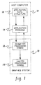
- FIG. 1 a general block diagram representation of the interaction between a graphics system 10 and a host computer 12 is shown.
- Computer 12 includes an application program 14 and an application data structure 16.
- Application program 14 stores into and retrieves data from application data structure 16 and sends graphics commands to graphics system 10.
- Data structure 16 holds descriptions of real or abstract figures or objects which are to appear on a graphics monitor (not shown) associated with system 10.
- An object description stored within data structure 16 comprises geometric coordinate data which defines the shape of components of the object, object attributes, and connectivity relationships and positioning data that define how the components fit together.
- objects are commonly defined by geometric primitives or polygons, such as quadrilaterals or triangles.
- Graphics system 10 includes a geometry processing engine 18 and a raster processing engine 20 coupled thereto.
- Engines 18 & 20 comprise separate sub- systems, each of which typically includes multiple pipelined or parallel connected processors.
- Engine 18 conventionally implements floating point geometry processing to convert information from modeling or world coordinates and colors to screen coordinates and colors through several well known processing steps, including tessellation, lighting calculation, clipping, transformation, mapping, etc. Certain of these processing steps are discussed further below as they relate to the present invention.
- Raster processing engine 20 traditionally implements a scan conversion operation wherein individual pixels are integer processed (e.g., through an edge processor and a span processor coupled thereto) for ultimate screen display.
- a typical shaded solid rendering system (which includes a geometry processing engine 18 and a raster processing engine 20) is initially discussed with reference to the structural/functional blocks of FIG. 2.
- Objects in a three-dimensional scene to be two-dimensionally represented are typically composed of surface polygons or specified in a functional or parametric way such as B-spline surfaces.
- Information such as X,Y,Z vertices in world coordinates and normals to the provided surfaces are commonly included.
- Engine 18 tessellates the provided information and implements well known lighting equations (e.g., Gouraud shading) using retrieved, predefined ambient, diffuse and specular lighting components.
- the color and intensity at each vertex is determined by lighting equations which consider object and ambient/light source color, direction of any light vector, surface and/or vertex normals, and the direction of the reflection vector if specular highlights are desired.
- Output in world coordinates from block 34 are polygon data vertices (X,Y,Z) and lighting intensity levels (R,G,B). This information is then clipped, projected and mapped at process block 36 to the desired viewport in screen coordinates.
- Input to raster processing engine 20 are the polygon vertices specified as integer X,Y,Z coordinates in screen space, and the R,G,B components of intensity. This information is fed to edge processing 38 which decomposes each triangle, for example, into a series of horizontal spans by interpolating the X,Z,R,G and B values with respect to Y between the vertices.
- Each span on a given scan line (Y value) consists of X(l) and X(r) (i.e., the horizontal left (l) and horizontal right (r) limits of the span), R,G,B and Z at the left edge and the partial derivatives of R,G,B and Z with respect to X (dR/dX, dG/dX, dB/dX, dZ/dX) as determined from the plane equation.
- the Y address (Y-ADDR) is made directly available to a frame buffer 42 and a Z-buffer 44 via line 39.
- a span processing operation 40 decomposes each horizontal span into individual pixels (and considers storing of intensity values to frame buffer 42) according to the following process:
- the derived X address (X-ADDR) is made available to both frame buffer 42 and Z-buffer 44, while the derived intensity values (R,G,B) are available only to buffer 42 and the computed Z depth value (Z VALUE) only to Z- buffer 44.
- Frame buffer 42 and Z-buffer 44 which can be accessed in parallel, each have a single entry for each (X,Y) pixel address.
- the comparison (Z(X,Y) > Z-BUFFER (X,Y)) ensures that only the pixels in a triangle that are closest to a viewer are written to frame buffer 42 after the entire scene has been processed.
- one pass through the data structure is sufficient to render a scene with light source shading of objects and hidden surface removal. Also, the order of processing is generally irrelevant, so no sorting of data is required.
- the calculation of R,G,B and Z as a function of X and Y is referred to in the art as 6-axis interpolation, since each vertex represents a point in 6-space.
- Buffer 42 is used to refresh a display monitor (not shown) via line 45.
- the present inventive shadowing technique is implemented within the raster processing sub-system of the graphics unit.
- the approach is functionally similar in several ways to that described above with respect to FIG. 2, however, a second Z-buffer is added to track pixel depth of geometric primitives relative to one or more discrete light sources applied to the scene to be represented. Multiple passes are made through the data structure for each light source capable of producing shadows in the scene.
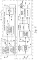
- FIG. 3 depicts a modified structural/functional graphics system pursuant to the present invention.
- System 100 also includes a raster processing engine 120 coupled to engine 118.
- Operationally engine 118 begins processing by tessellating and applying lighting equations 134 to the retrieved data.
- function block 134 In addition to forwarding, for example, polygon data vertices X,Y,Z in world coordinates and color intensities R,G,B to the clip, project and map function 136 of engine 118, function block 134 also generates polygon data vertices Xs,Ys,Zs in world coordinates.
- a second Z-buffer 144 is provided pursuant to the present invention for accommodating Zs values representative of the pixel depth from the point of view of a predefined light source rather than from a viewer.
- the pixel addresses to the second Z-buffer are designated Xs,Ys and are not the same X,Y pixel addresses which access a frame-buffer 142 and a first Z-buffer 143 (i.e., viewpoint Z-buffer).
- the shadow generation algorithm set forth herein operates by taking multiple passes over the data, depending upon the number of light sources in the scene.
- a first pass the scene is rendered to the frame-buffer in the usual way, updating the first Z-buffer with the viewpoint Z-value, but using only the ambient component of the light specification to determine the corresponding color values R,G,B to be stored.
- first pass processing is essentially as described above with reference to FIG. 2.
- Input to raster processing engine 120 are the polygon vertices specified as integer X,Y,Z coordinates and Xs,Ys,Zs coordinates in screen space, and the R,G,B components of intensity due to the defined lighting.
- This information is fed to polygon edge processing 138 which decomposes each triangle, for example, into a series of horizontal spans by interpolating the X,Z,Xs,Ys,Zs,R,G & B values with respect to Y between the vertices.
- Each span on a given scan line (Y value) consists of X(l) and X(r) (i.e., the horizontal left (l) and horizontal right (r) limits of the span), R,G,B,X,Z,Xs,Ys & Zs at the left edge and the partial derivatives of Z,R,G,B,Xs,Ys & Zs with respect to X as determined from the plane equation.
- the Y address (Y- ADDR) is made directly available to frame buffer 142 and first Z-buffer 143 via line 139.
- a span processing operation 140 subsequently decomposes each horizontal span into individual pixels as described further below.
- Buffer 142 is used to refresh a display monitor (not shown) via line 145.
- the frame-buffer contains the scene as it would appear if no specific light sources, besides ambient lighting, were identified.
- the resultant screen image appears dim.
- the first Z-buffer (viewpoint Z-buffer) contains the Z values for the pixels which represent the closest points to the viewer in viewpoint coordinate space.
- a transformation matrix is set up in such a way that the viewpoint is moved to the position of a light source.
- the scene is then rendered in the usual way except that the frame-buffer is not updated, and the second, light source view Z-buffer is used instead of the first, viewpoint view Z-buffer.
- the shaded image and shadows are generated in parallel.
- the transform/clip/map process 136 generates vertex data relative to both the light source and the viewpoint, and the lighting calculations generate the intensity based on the diffuse and the specular components of the subject light source with no ambient lighting considered.
- Input to edge processing then consists of triangles with 9-valued vertices, and interpolation proceeds in 9-space.
- each vertex consists of:
- Span processing proceeds by interpolating R,G,B,Z,Xs,Ys,Zs between X(l) and X(r), using both the first and second Z-buffers 143 & 144, respectively, to decide whether to update the frame buffer 142. Since processing only involves the diffuse and specular components for one light source, a compare in the second Z-buffer (light source view Z-buffer) that indicates a no write condition corresponds to a shadow, with only the ambient background remaining in the frame buffer. When the frame buffer is updated, it is accomplished in a cumulative manner with each computed intensity value being added to the value already there. In this way, multiple light sources are accumulated on the image.
- Stored information typically includes a list of 3D geometric primitives (polygons, surfaces, etc.) and their attributes (color, surface properties, etc.) which compose the scene to be rendered, specified in or transformable to world coordinates.
- viewing information including position of the viewer in world coordinates, size and orientation of viewing window in world coordinates, screen viewport in device coordinates, clipping planes defined in world coordinates and the type of projection (i.e., orthogonal or perspective) are defined.
- an ambient light component is also predefined.
- the ambient light component simulates background light illuminating a surface totally in shadow, and is constant for every surface in the scene.
- matrix Mi is used to transform the vertices of the scene primitives in world coordinates to device coordinates viewed from each light source position (i) through a suitable selection of a window and viewport mapping so as to place the total scene within the confines of the light source Z-buffer device coordinate range.
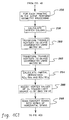
- the first processing pass (PASS 1) through the data structure begins with routine geometry processing and includes transformation of triangle vertices to device coordinates using matrix Mv, 210 "For Each Primitive In The Scene Perform Geometry Processing & Transform Triangle Vertices To Device Coordinates Using Matrix Mv.”
- Typical geometric processing includes fetching the primitives from data memory, transforming vertices and control points to world coordinates (if necessary), tessellating primitives into planar polygons such as triangles (if necessary), performing a clipping test and (if necessary) clipping to a defined view volume. Each of these manipulations is well understood by those skilled in the art.
- perspective division may be performed, again if required.
- edges are scan converted into a series of horizontal or vertical spans, 212 "Scan Convert Edges Into Series Of Horizontal Spans.” This typically involves computation of Bresenham parameters or DDA slopes for scan converting of triangle edges and then scan converting the edges into end points of a series of horizontal (or alternatively vertical) spans.
- Each X position in each horizontal span is next considered for computation and storage of Z values. This is accomplished by first selecting a horizontal span for processing, 214 "Select A (Next) Horizontal Span For Processing,” after which a pixel X position in the selected span is selected, 216 "Select A (Next) Pixel X Position In Selected Span.” A depth value for the selected pixel is computed and compared to the corresponding contents of the first Z-buffer, 218 "Compute Z Value Of Selected Pixel And Compare To Corresponding Contents of First Z-Buffer.” Logical inquiry is then conducted into whether the selected pixel is visible to the viewpoint, 220 “Is Selected Pixel Visible?" If “yes” (meaning that the calculated Z value is closer to the eyepoint than the corresponding value in the first Z-buffer), then the Z-buffer value is replaced with the just calculated pixel Z value and the frame buffer pixel value is replaced with the corresponding ambient color value, 222 "Update First Z-Buffer With Pixel Z Value & Update Frame Buffer With Ambient
- processing passes through junction 224 to inquire whether all pixels in the subject span have been processed, 226 "All Pixels in Span Selected?" (Alternatively, if the selected pixel is not visible to the viewpoint, processing proceeds directly from inquiry 220 through junction 224 to inquiry 226.) While the answer to inquiry 226 remains “no,” processing continues to loop back to instruction 216 for selection of a next pixel X position in the selected span. Once all pixels in a selected span have been processed, inquiry is made into whether all spans have been selected for processing, 228 "All Spans Selected?" If “no,” processing returns to instruction 214 for selection of a next horizontal span. If "yes,” then first pass processing (PASS 1) through the data structure is complete and processing proceeds to FIG. 4B.
- PASS 1 first pass processing
- the second pass includes performing geometry processing and transforming triangle vertices to device coordinates (i.e., light source view coordinates) using the corresponding matrix Mi, 234 "For Each Primitive In The Scene, Perform Geometry Processing And Transform Triangle Vertices to Device Coordinates Using Matrix Mi.”
- geometry processing might include fetching a primitive from data memory, transforming vertices and control points to world coordinates (if necessary), tessellating primitives into planar polygons (if necessary), performing clip testing and clipping to a view volume (if necessary). Thereafter, edges are scan converted into a series of horizontal spans, 236 "Scan Convert Edges Into Series Of Horizontal Spans.” Instruction 236 includes computing Bresenham parameters or DDA slopes for scan converting of the triangle edges and actual scan conversion of the triangle edges into end points of a series of horizontal (or alternatively vertical) spans.
- Depth buffer processing similar to that conducted in FIG. 4A next occurs. Namely, a horizontal span for processing is initially selected, 238 "Select A (Next) Horizontal Span For Processing," and a pixel Xs position therein is identified, 240 "Select A (Next) Pixel Xs Position In Selected Span.” The depth value of the selected Xs pixel is interpolated and compared to the stored value in the corresponding location of the second Z-buffer, 242 "Compute Z Value of Selected Pixel and Compare to Corresponding Contents of Second Z-Buffer.” Inquiry is then made into whether the selected pixel is visible to the subject light source, 244 "Is Selected Pixel Visible To Light Source (i)?" If "yes,” then the corresponding location in the second Z-buffer is updated with the just calculated pixel depth value Zs, 246 "Update Second Z-Buffer With Pixel Zs Value.” Once updated, or if the subject pixel is not visible to the light source (e.g., its in shadow), processing passes through
- initial geometry processing is performed, 256 "For Each Primitive In The Scene Perform Geometry Processing.” Processing includes fetching a primitive from data memory, transforming vertices and control points to world coordinates (if necessary), tessellating primitives into planar polygons (if necessary) and clipping to a view volume (if necessary).
- vertex normals are to be transformed to world coordinates, i.e., if not already therein.
- vertex colors are calculated, 258 "Calculate Vertex Colors.” The colors are calculated from the specular and diffuse lighting equations only, using the primitive, surface and color attributes, the vertex normals, the viewing parameters and light source attributes.
- triangle vertices are transformed to device coordinates using matrix Mv 260 "Transform Triangle Vertices to Device Coordinates Using Matrix Mv,” and triangle vertices are also transformed to device coordinates using the subject light source matrix Mi, 262 "Transform Triangle Vertices to Device Coordinates Using Matrix Mi.”
- the partial derivatives for the light source device coordinates are then calculated, 264 "Calculate Partial Derivatives dZs/dXs and dZs/dYs.”
- a processing step is inserted at this point whereby vertex values of Zs are adjusted toward the subject light source (i) by a bias value equal to the sum of the calculated derivatives.
- a bias value equal to the sum of the calculated derivatives.
- pixel E has a Zs value of 8, but maps to Z-buffer 2 with a value of 14 (calculated when the Zs values are interpolated against Xs,Ys instead of X,Y). This pixel would be determined to be in shadow without some compensation.
- the problem is not unique to the present invention, e.g., see the above-referenced Williams article.
- the solution presented therein was to add a bias to the calculated Zs values to prevent the effect when each point is transformed to the light source view. Since the present invention interpolates within the polygon rather than transforming each point, the bias is added to the Zs values of, for example, the triangle vertices. Furthermore, greater accuracy is obtained by calculating the biases as a function of the actual surface gradient of the polygon with respect to the light source viewpoint Xs,Ys plane. This yields a more accurate result then the constant bias proposed in the Williams article.
- the edge processing function when it is calculating the derivatives for span generation, it also calculates the values of dZs/dXs and dZs/dYs, and adjusts the vertex Zs value by the sum of the derivatives. This has the effect of moving the triangle closer to the light source by its surface gradient in Xs and Ys and causes proper registration of the Xs,Ys plane.
- scan conversion of edges into a series of horizontal spans next occurs, 268 "Scan Convert Edges Into Series of Horizontal Spans.” This involves computation of the Bresenham parameters or DDA slopes for scan converting the triangle edges to produce X,Y,Z,R,G,B,Xs,Ys & Zs, and then scan converting of the triangle edges into the end points of a series of horizontal (or alternatively vertical) spans.
- a pixel X position is identified by first selecting a horizontal span for processing, 270 "Select A (Next) Horizontal Span For Processing," and then selecting a pixel position within that span, 272 "Select A (Next) Pixel X Position In Selected Span.”
- the Z value of the selected pixel is then computed and compared to the contents of the viewpoint depth buffer, 274 "Compute Z Value of Selected Pixel and Compare To Corresponding Contents of First Z-Buffer.”
- the Xs,Ys,Zs values of the selected pixel are computed/interpolated and the calculated Zs value is compared to the contents of the second Z-buffer at location Xs,Ys, 276 "Compute Xs,Ys,Zs Values of Selected Pixel and Compare Zs to Contents of Second Z- Buffer At Location Xs,Ys.”
- Inquiry is then made into whether the selected pixel is visible from both the viewpoint and the subject light source (i), 278 "Is Selected Pixel Visible
- the frame buffer contains the sum of color intensities due to any ambient light and each of the defined light sources (i), including any shadows defined thereby, and processing is terminated, 290 "End.”
- Shadow processing pursuant to the invention attains a performance comparable to non- shadowed, shaded polygons with hidden surfaces removed.
- the approach is implemented primarily in hardware and maintains a mapping between a viewpoint and a light source by interpolating the respective Z-buffer addresses into dual Z-buffers during span generation.
- Novel characteristics include the use of 9-axis interpolation instead of the traditional 6-axis, accommodation of multiple light sources through a simple technique of multiple passes over the scene, and correction of depth buffer registration errors by Z displacement in the direction of a light source view gradient in Xs,Ys space (light source view coordinates).
Abstract
A computer graphics display system and method are described for rendering a scene formed of at least one geometric primitive as a pixel image having shadows produced by at least one defined light source. Multiple passes are made through the primitive data structure for each light source capable of producing shadows in the scene to be rendered. In a first pass, the scene is rendered to a frame buffer in the usual way, but using only the ambient component of the light specification, and a first Z-buffer is updated with the viewpoint Z value. For each defined light source (i), two additional passes (PASS 2i and 2i+1) through the data structure are required. In the first of these, a transformation matrix is set up in such a way that the viewpoint is moved to the position of the light source. The scene is then rendered in the usual way except that the frame buffer is not updated, and a second Z-buffer (light source view Z-buffer) is used instead of the first Z-buffer. In the next pass, the shaded image and shadows are generated in parallel using the content of the first and second Z-buffers. When the frame buffer is updated, it is accomplished in a cumulative manner with each computed intensity value due to a specific light source being added to any value already stored there. In this way, intensities resultant from each of multiple light sources are accumulated on the image.
Description
- The present invention relates generally to computer graphics generation and display, and more particularly, to a method and system for rendering a scene formed of at least one geometric primitive as a pixel image having a shadow(s) cast by another geometric primitive which is blocking the illumination of one or more defined light source(s).
- The quality of computer graphics display system images and the time required to process these images have been steadily improving with each new generation of graphics display equipment. Continued improvement is clearly beneficial since images which approach photographic quality and project a real-world paradigm are much easier to interpret, while high speed processing allows more productive user interaction with displayed images. For example, currently available graphics display systems are able to provide highly interactive images with shading of displayed objects. Screen shading accurately models the surface effects of different types of lighting sources on displayed objects and the shading effects provide visible cues as to the shape and contours of the objects. Much of the processing required to produce shading effects is done in hardware which interpolates colors between polygon vertices, e.g., using a well known technique such as Gouraud Shading.
- Other visual cues such as surface textures, motion blur, object reflections and shadows can also be added to an image to further improve its quality. However, these enhancements traditionally require extensive software processing cycles, which make the graphics system less user interactive. The present invention specifically addresses improving the processing time for one of these enhancements, namely, generating shadows cast when objects block the illumination of one or more defined light sources in a scene to be rendered.
- Typical computer graphics systems are capable of determining the surface color of an object at a given pixel and whether a pixel is visible from a defined viewpoint, and therefore whether the pixel belongs in the associated frame buffer. To accomplish this it is necessary to perform an interpolation of R,G,B and Z in X,Y space (six-axis interpolation). Since any information as to the positional relationship between light sources and objects is discarded by the geometry processing engine of the graphics system after the lighting calculation step, it is impossible for the subsequent raster processing sub-system to determine if an object casts a shadow on another object to appear in the pixel image.
- As described by P. Bergeron in an IEEE September, 1986 publication entitled "A General Version of Crow's Shadow Volumes" (pp. 17-28), there are presently five known classes of shadow generation algorithms. Namely:
- (1) Shadow computation during display (A. Appel, "Some Techniques for Shading Machine Renderings of Solids," Proc. Spring Joint Computer Conference, Thompson Books, Washington, DC, pp. 37-45, 1968);
- (2) Polygon shadow generation based on clipping transformation (Atherton and Weiler, "Polygon Shadow Generation," Computer Graphics, (Proc. SIGGRAPH 78) Vol. 12, No. 3, pp. 275-281, July 1978;
- (3) Shadow volumes (F. Crow, "Shadow Algorithms for Computer Graphics," Computer Graphics, (Proc. SIGGRAPH 77) Vol. 11, No. 3, pp. 242-248, July 1977;
- (4) Z-buffer shadow computation (L. Williams, "Casting Curved Shadows on Curved Surfaces," Computer Graphics, (Proc. SIGGRAPH 78), Vol. 12, No. 3, pp. 270-274, July 1978; and
- (5) Ray tracing (see Whitted, " An Improved Illumination Model for Shaded Display," Comm. ACM, Vol. 23, No. 6, pp. 343-349, June 1980).
- The Williams algorithm begins by calculating and storing just the Z-buffer values for an image from the perspective of the light source, wherein increasing values represent increasing distance. Next, the Z-buffer and the image are calculated from the viewpoint of an observer using a Z-buffer algorithm with the following modification. Whenever a pixel is determined to be visible, its object-precision coordinates in the observer's view (X₀,Y₀,Z₀) are each computationally transformed into coordinates in the light source's view (X'₀,Y'₀,Z'₀). The transformed coordinates X'₀ and Y'₀ are used to select a value ZL in the light source's Z- buffer to be compared with the transformed value Z'₀. If ZL is closer to the light source than is Z'₀, then there is something blocking the light from that point, and the pixel is shaded as being in shadow; otherwise, the point is visible from the light and it is shaded as being lighted. This computationally intensive approach requires extensive transformation calculations between the light source and viewpoint view coordinates for each pixel. Because of these computations, user interactiveness with the computer graphics system is less than optimal, and degrades significantly with the addition of a second or more light source.
- Thus, a need continues to exist in the computer graphics processing art for a new shadow generation technique which solves the shadow generation problem in image space and improves upon the performance of previous shadowing approaches.
- Briefly described, this invention provides a computer graphics display method and system for rendering a scene formed of at least one geometric primitive as a pixel image with shadow(s) resulting from other object blocking illumination from one or more defined light sources. The graphics display system includes a first Z-buffer, a second Z-buffer and a frame buffer, each of which has storage locations corresponding to the pixels which are to form the image. The image has a defined viewpoint and at least one light source, such that each primitive is represented by one or more pixels (X,Y) relative to the defined viewpoint and one or more pixels (Xs,Ys) relative to the defined light source. In one embodiment, the image rendering method includes the steps of: for each pixel (X,Y), generating a first depth value (Z) representative of the depth from the defined viewpoint to that pixel and saving the first depth value in the corresponding pixel location of the first Z-buffer if the first depth value (Z) is visible to the defined viewpoint in comparison with the depth value stored in the corresponding pixel location of the first Z-buffer; for each pixel (Xs,Ys), generating a second depth value (Zs) representative of the depth of the pixel to the defined light source and saving the second depth value (Zs) in the corresponding pixel location of the second Z-buffer if the second depth value (Zs) is visible to the light source in comparison with a depth value stored in the corresponding pixel location of the second Z-buffer; and for each pixel forming the pixel image, generating, using only the defined light source, a representative color value (Rs,Gs,Bs) and adding to a corresponding (X,Y) pixel location of the frame buffer the representative color value (Rs,Gs,Bs) for the pixel if the corresponding depth value in the first Z-buffer identifies a pixel visible to the viewpoint and if the corresponding depth value in the second Z-buffer identifies a pixel visible to the light source. Further specific method details and enhancements are also described and claimed.
- In another aspect, the invention provides a computer graphics display system with shadow generation capability for rendering a scene formed of at least one geometric primitive as a pixel image. The scene to be rendered includes a defined ambient lighting value, viewpoint and light source such that each primitive has one or more pixel (X,Y) associated therewith in a first, viewpoint coordinate space, and one or more pixel (Xs,Ys) associated therewith in a second, light source coordinate space. The graphics display system includes a geometry processing engine for converting the at least one geometric primitive into device X,Y,Z coordinates relative to the viewpoint and device Xs,Ys,Zs coordinates relative to the light source. A frame buffer, first Z-buffer and second Z-buffer are also provided, each of which has storage locations corresponding to the pixels forming the image of the rendered scene. A raster processing engine is coupled to receive the output of the geometry processing engine, and is also coupled to the frame buffer, first Z-buffer and second Z-buffer for controlling the storage of values thereto. The raster processing engine includes: first storage means which directs the storage of pixel depth values in the first Z-buffer whenever a determined pixel depth value (Z) is equal or closer to the viewpoint than a depth value already stored in the corresponding pixel location of the first Z-buffer; second storage means which directs the storage of second pixel depth values (Zs) in the second Z-buffer whenever a determined depth value (Zs) is equal or closer to the light source than a depth value already stored in the corresponding pixel location of the second Z-buffer; generating means for producing a representative color value (Rs,Gs,Bs) for each pixel forming the image using only the defined lighting source; and accumulating means for adding to the corresponding (X,Y) pixel location of the frame buffer the generated representative color value (Rs,Gs,Bs) for the pixel if the corresponding depth value in the first Z-buffer identifies a pixel visible to the viewpoint and the corresponding depth value in the second Z-buffer identifies a pixel visible to the light source.
- To summarize, the present invention comprises a shadow generation approach which advantageously enhances processing times in comparison with known shadow rendering techniques, so that user interactiveness with the graphics system is optimized.
- These and other objects, advantages and features of the present invention will be more readily understood from the following detailed description of certain preferred embodiments of the present invention, when considered in conjunction with the accompanying drawings in which:
- FIG. 1 is a general block diagram representation of an interactive computer graphics display system of the present invention;
- FIG. 2 is a block diagram representation of a conventional computer graphics display system;
- FIG. 3 is a block diagram representation of a computer graphics display system pursuant to the present invention;
- FIG.S 4A, 4B, 4C1 & 4C2 comprise a flowchart representation of one embodiment of pixel image processing pursuant to the computer graphics display system of FIG. 3; and
- FIG. 5 graphically illustrates a potential problem arising with use of the computer graphics display system of FIG. 3, which is addressed by the pixel image processing method of FIG.S 4A-4C2.
- Reference is now made to the drawings in which the same reference numbers are used throughout the different figures to designate the same or similar components.
- In FIG. 1, a general block diagram representation of the interaction between a
graphics system 10 and ahost computer 12 is shown.Computer 12 includes anapplication program 14 and anapplication data structure 16.Application program 14 stores into and retrieves data fromapplication data structure 16 and sends graphics commands tographics system 10.Data structure 16 holds descriptions of real or abstract figures or objects which are to appear on a graphics monitor (not shown) associated withsystem 10. An object description stored withindata structure 16 comprises geometric coordinate data which defines the shape of components of the object, object attributes, and connectivity relationships and positioning data that define how the components fit together. For example, objects are commonly defined by geometric primitives or polygons, such as quadrilaterals or triangles. -
Graphics system 10 includes ageometry processing engine 18 and araster processing engine 20 coupled thereto.Engines 18 & 20 comprise separate sub- systems, each of which typically includes multiple pipelined or parallel connected processors.Engine 18 conventionally implements floating point geometry processing to convert information from modeling or world coordinates and colors to screen coordinates and colors through several well known processing steps, including tessellation, lighting calculation, clipping, transformation, mapping, etc. Certain of these processing steps are discussed further below as they relate to the present invention.Raster processing engine 20 traditionally implements a scan conversion operation wherein individual pixels are integer processed (e.g., through an edge processor and a span processor coupled thereto) for ultimate screen display. - To facilitate a description of the unique structure/function of a shadow generation unit in accordance with the present invention, the operation of a typical shaded solid rendering system (which includes a
geometry processing engine 18 and a raster processing engine 20) is initially discussed with reference to the structural/functional blocks of FIG. 2. - Information in an associated
application data structure 16, including a3D object database 30 and alight source database 32, is retrieved bygeometry processing engine 18 ofgraphics system 10. Objects in a three-dimensional scene to be two-dimensionally represented are typically composed of surface polygons or specified in a functional or parametric way such as B-spline surfaces. Information such as X,Y,Z vertices in world coordinates and normals to the provided surfaces are commonly included.Engine 18 tessellates the provided information and implements well known lighting equations (e.g., Gouraud shading) using retrieved, predefined ambient, diffuse and specular lighting components. - During the
lighting calculation process 34, the color and intensity at each vertex is determined by lighting equations which consider object and ambient/light source color, direction of any light vector, surface and/or vertex normals, and the direction of the reflection vector if specular highlights are desired. Output in world coordinates fromblock 34 are polygon data vertices (X,Y,Z) and lighting intensity levels (R,G,B). This information is then clipped, projected and mapped atprocess block 36 to the desired viewport in screen coordinates. - Input to
raster processing engine 20 are the polygon vertices specified as integer X,Y,Z coordinates in screen space, and the R,G,B components of intensity. This information is fed to edge processing 38 which decomposes each triangle, for example, into a series of horizontal spans by interpolating the X,Z,R,G and B values with respect to Y between the vertices. Each span on a given scan line (Y value) consists of X(l) and X(r) (i.e., the horizontal left (l) and horizontal right (r) limits of the span), R,G,B and Z at the left edge and the partial derivatives of R,G,B and Z with respect to X (dR/dX, dG/dX, dB/dX, dZ/dX) as determined from the plane equation. The Y address (Y-ADDR) is made directly available to aframe buffer 42 and a Z-buffer 44 vialine 39. Aspan processing operation 40 decomposes each horizontal span into individual pixels (and considers storing of intensity values to frame buffer 42) according to the following process:
The derived X address (X-ADDR) is made available to bothframe buffer 42 and Z-buffer 44, while the derived intensity values (R,G,B) are available only to buffer 42 and the computed Z depth value (Z VALUE) only to Z-buffer 44. -
Frame buffer 42 and Z-buffer 44, which can be accessed in parallel, each have a single entry for each (X,Y) pixel address. The comparison (Z(X,Y) > Z-BUFFER (X,Y)) ensures that only the pixels in a triangle that are closest to a viewer are written to framebuffer 42 after the entire scene has been processed. Typically, one pass through the data structure is sufficient to render a scene with light source shading of objects and hidden surface removal. Also, the order of processing is generally irrelevant, so no sorting of data is required. The calculation of R,G,B and Z as a function of X and Y, is referred to in the art as 6-axis interpolation, since each vertex represents a point in 6-space.Buffer 42 is used to refresh a display monitor (not shown) vialine 45. - Of the known classes of shadow generation algorithms (see Background section), most if not all, are implemented in the geometry processing phase of the graphics system. For example, see the Z-buffer shadow computation approach described by L. Williams in the above-referenced article, entitled "Casting Curved Shadows on Curved Surfaces." Such an approach, however, is similar to having dual pipelines and managing them simultaneously. Obviously, with the addition of multiple light sources the image-precision calculations of the Williams approach quickly become too complex.
- In contrast to most previous shadowing approaches, the present inventive shadowing technique is implemented within the raster processing sub-system of the graphics unit. The approach is functionally similar in several ways to that described above with respect to FIG. 2, however, a second Z-buffer is added to track pixel depth of geometric primitives relative to one or more discrete light sources applied to the scene to be represented. Multiple passes are made through the data structure for each light source capable of producing shadows in the scene. An overview of this technique is next discussed with reference to FIG. 3, which depicts a modified structural/functional graphics system pursuant to the present invention.
- As shown, information from an associated application data structure 116 (including a
3D object database 130 and a light source database 132) of ahost computer 112 is initially fed to ageometry processing engine 118 ofgraphics system 100.System 100 also includes araster processing engine 120 coupled toengine 118. Operationallyengine 118 begins processing by tessellating and applyinglighting equations 134 to the retrieved data. In addition to forwarding, for example, polygon data vertices X,Y,Z in world coordinates and color intensities R,G,B to the clip, project andmap function 136 ofengine 118,function block 134 also generates polygon data vertices Xs,Ys,Zs in world coordinates. Vertices Xs,Ys,Zs represent the retrieved data vertices defined in relation to the light source(s) applied to the scene to be rendered, i.e., polygon data vertices Xs,Ys,Zs are generated in each of one or more light source view coordinates Xs,Ys,Zs (wherein s=1,...N light sources). - A second Z-
buffer 144 is provided pursuant to the present invention for accommodating Zs values representative of the pixel depth from the point of view of a predefined light source rather than from a viewer. The pixel addresses to the second Z-buffer (i.e., the light source view buffer) are designated Xs,Ys and are not the same X,Y pixel addresses which access a frame-buffer 142 and a first Z-buffer 143 (i.e., viewpoint Z-buffer). - As described further below, the shadow generation algorithm set forth herein operates by taking multiple passes over the data, depending upon the number of light sources in the scene. In a first pass, the scene is rendered to the frame-buffer in the usual way, updating the first Z-buffer with the viewpoint Z-value, but using only the ambient component of the light specification to determine the corresponding color values R,G,B to be stored. Other than using only ambient light in the lighting calculation, first pass processing is essentially as described above with reference to FIG. 2.
- Input to
raster processing engine 120 are the polygon vertices specified as integer X,Y,Z coordinates and Xs,Ys,Zs coordinates in screen space, and the R,G,B components of intensity due to the defined lighting. This information is fed topolygon edge processing 138 which decomposes each triangle, for example, into a series of horizontal spans by interpolating the X,Z,Xs,Ys,Zs,R,G & B values with respect to Y between the vertices. Each span on a given scan line (Y value) consists of X(l) and X(r) (i.e., the horizontal left (l) and horizontal right (r) limits of the span), R,G,B,X,Z,Xs,Ys & Zs at the left edge and the partial derivatives of Z,R,G,B,Xs,Ys & Zs with respect to X as determined from the plane equation. The Y address (Y- ADDR) is made directly available to frame buffer 142 and first Z-buffer 143 vialine 139. Aspan processing operation 140 subsequently decomposes each horizontal span into individual pixels as described further below. Buffer 142 is used to refresh a display monitor (not shown) vialine 145. - After completing the first pass, the frame-buffer contains the scene as it would appear if no specific light sources, besides ambient lighting, were identified. The resultant screen image appears dim. The first Z-buffer (viewpoint Z-buffer) contains the Z values for the pixels which represent the closest points to the viewer in viewpoint coordinate space.
- For each defined light source, two additional processing passes through the data structure are required. In the first of these, a transformation matrix is set up in such a way that the viewpoint is moved to the position of a light source. The scene is then rendered in the usual way except that the frame-buffer is not updated, and the second, light source view Z-buffer is used instead of the first, viewpoint view Z-buffer.

In the next pass, the shaded image and shadows are generated in parallel. The transform/clip/map process 136 generates vertex data relative to both the light source and the viewpoint, and the lighting calculations generate the intensity based on the diffuse and the specular components of the subject light source with no ambient lighting considered. Input to edge processing then consists of triangles with 9-valued vertices, and interpolation proceeds in 9-space. In particular, each vertex consists of: - X
- - screen space X coordinate (from viewpoint)
- Y
- - screen space Y coordinate (from viewpoint)
- Z
- - screen space Z coordinate (from viewpoint)
- R
- - red component of intensity for light
- G
- - green component of intensity for light
- B
- - blue component of intensity for light
- Xs
- - screen space X coordinate (from light source)
- Ys
- - screen space Y coordinate (from light source)
- Zs
- - screen space Z coordinate (from light source)
- Span processing proceeds by interpolating R,G,B,Z,Xs,Ys,Zs between X(l) and X(r), using both the first and second Z-
buffers 143 & 144, respectively, to decide whether to update the frame buffer 142. Since processing only involves the diffuse and specular components for one light source, a compare in the second Z-buffer (light source view Z-buffer) that indicates a no write condition corresponds to a shadow, with only the ambient background remaining in the frame buffer. When the frame buffer is updated, it is accomplished in a cumulative manner with each computed intensity value being added to the value already there. In this way, multiple light sources are accumulated on the image. As displayed on the monitor (not shown), the visual effect after each light source is processed is of turning a light "on". The algorithm for span processing on the third pass is:
A more specific explanation of the processing technique of the present invention is next described with reference to the functional flowcharts of FIG.S 4A, 4B, 4C1 & 4C2. - Referring first to FIG. 4A, upon initiating processing, 200 "Start," input information stored in data memory is retrieved, 202 "Retrieve Given Information Stored In Data Memory." Stored information typically includes a list of 3D geometric primitives (polygons, surfaces, etc.) and their attributes (color, surface properties, etc.) which compose the scene to be rendered, specified in or transformable to world coordinates. In addition, viewing information including position of the viewer in world coordinates, size and orientation of viewing window in world coordinates, screen viewport in device coordinates, clipping planes defined in world coordinates and the type of projection (i.e., orthogonal or perspective) are defined. Also, a list of N light sources and their attributes (color, spread, type, etc.) and position (or light ray direction if infinite) are specified in world coordinates. Typically, an ambient light component is also predefined. The ambient light component simulates background light illuminating a surface totally in shadow, and is constant for every surface in the scene.
- Next, the frame buffer, first Z-buffer and second Z-buffer are cleared, 204 "Clear Frame Buffer, First Z-Buffer, & Second Z-Buffer," and a viewpoint transformation matrix Mv is created 206 "Create Viewpoint Transformation Matrix Mv." Matrix Mv is used to transform the vertices of scene primitives in world coordinates to device coordinates viewed from the viewpoint position using the given window and viewport size and orientation. Thereafter, a light source transformation matrix Mi, wherein i=1...N is created for each of the N defined light sources, 208 "Create Light Source Transformation Matrix Mi, Wherein i=1...N Light Sources." For each light source, matrix Mi is used to transform the vertices of the scene primitives in world coordinates to device coordinates viewed from each light source position (i) through a suitable selection of a window and viewport mapping so as to place the total scene within the confines of the light source Z-buffer device coordinate range. One skilled in the art will understand how to implement such a selection.
- The first processing pass (PASS 1) through the data structure begins with routine geometry processing and includes transformation of triangle vertices to device coordinates using matrix Mv, 210 "For Each Primitive In The Scene Perform Geometry Processing & Transform Triangle Vertices To Device Coordinates Using Matrix Mv." Typical geometric processing includes fetching the primitives from data memory, transforming vertices and control points to world coordinates (if necessary), tessellating primitives into planar polygons such as triangles (if necessary), performing a clipping test and (if necessary) clipping to a defined view volume. Each of these manipulations is well understood by those skilled in the art. Along with transforming triangle vertices to device coordinates using the matrix Mv, perspective division may be performed, again if required. After converting the vertices to device coordinates, edges are scan converted into a series of horizontal or vertical spans, 212 "Scan Convert Edges Into Series Of Horizontal Spans." This typically involves computation of Bresenham parameters or DDA slopes for scan converting of triangle edges and then scan converting the edges into end points of a series of horizontal (or alternatively vertical) spans.
- Each X position in each horizontal span is next considered for computation and storage of Z values. This is accomplished by first selecting a horizontal span for processing, 214 "Select A (Next) Horizontal Span For Processing," after which a pixel X position in the selected span is selected, 216 "Select A (Next) Pixel X Position In Selected Span." A depth value for the selected pixel is computed and compared to the corresponding contents of the first Z-buffer, 218 "Compute Z Value Of Selected Pixel And Compare To Corresponding Contents of First Z-Buffer." Logical inquiry is then conducted into whether the selected pixel is visible to the viewpoint, 220 "Is Selected Pixel Visible?" If "yes" (meaning that the calculated Z value is closer to the eyepoint than the corresponding value in the first Z-buffer), then the Z-buffer value is replaced with the just calculated pixel Z value and the frame buffer pixel value is replaced with the corresponding ambient color value, 222 "Update First Z-Buffer With Pixel Z Value & Update Frame Buffer With Ambient Color Value."
- From
instruction 222 processing passes throughjunction 224 to inquire whether all pixels in the subject span have been processed, 226 "All Pixels in Span Selected?" (Alternatively, if the selected pixel is not visible to the viewpoint, processing proceeds directly frominquiry 220 throughjunction 224 toinquiry 226.) While the answer toinquiry 226 remains "no," processing continues to loop back toinstruction 216 for selection of a next pixel X position in the selected span. Once all pixels in a selected span have been processed, inquiry is made into whether all spans have been selected for processing, 228 "All Spans Selected?" If "no," processing returns toinstruction 214 for selection of a next horizontal span. If "yes," then first pass processing (PASS 1) through the data structure is complete and processing proceeds to FIG. 4B. - FIG.S 4B, 4C1 & 4C2 together represent the two novel passes through the data structure pursuant to the present invention which are to be accomplished in combination for each defined light source (i.e., PASS 2i and PASS 2i+1, wherein i=1...N, and N equals the number of light sources).
- Initially, a defined light source is selected, 230 "Select A (Next) Defined Light Source (i)," and the second Z-buffer is cleared, 232 "Clear Second Z- Buffer." Thereafter, for each primitive in the data structure the second pass (PASS 2i) includes performing geometry processing and transforming triangle vertices to device coordinates (i.e., light source view coordinates) using the corresponding matrix Mi, 234 "For Each Primitive In The Scene, Perform Geometry Processing And Transform Triangle Vertices to Device Coordinates Using Matrix Mi."
- Again, geometry processing might include fetching a primitive from data memory, transforming vertices and control points to world coordinates (if necessary), tessellating primitives into planar polygons (if necessary), performing clip testing and clipping to a view volume (if necessary). Thereafter, edges are scan converted into a series of horizontal spans, 236 "Scan Convert Edges Into Series Of Horizontal Spans."
Instruction 236 includes computing Bresenham parameters or DDA slopes for scan converting of the triangle edges and actual scan conversion of the triangle edges into end points of a series of horizontal (or alternatively vertical) spans. - Depth buffer processing similar to that conducted in FIG. 4A next occurs. Namely, a horizontal span for processing is initially selected, 238 "Select A (Next) Horizontal Span For Processing," and a pixel Xs position therein is identified, 240 "Select A (Next) Pixel Xs Position In Selected Span." The depth value of the selected Xs pixel is interpolated and compared to the stored value in the corresponding location of the second Z-buffer, 242 "Compute Z Value of Selected Pixel and Compare to Corresponding Contents of Second Z-Buffer." Inquiry is then made into whether the selected pixel is visible to the subject light source, 244 "Is Selected Pixel Visible To Light Source (i)?" If "yes," then the corresponding location in the second Z-buffer is updated with the just calculated pixel depth value Zs, 246 "Update Second Z-Buffer With Pixel Zs Value." Once updated, or if the subject pixel is not visible to the light source (e.g., its in shadow), processing passes through
junction 248 toinquiry 250 "All Pixels In Span Selected?" Processing then continues to loop back toinstruction 240 to select a next pixel Xs position in the selected span until all pixels in the span have been processed. Thereafter, inquiry is made whether all spans have been selected, 252 "All Spans Selected?" If "no," processing returns toinstruction 238 where the next span is selected. Once all spans have been selected, the second pass is complete and processing passes to FIG.S 4C1 & 4C2 for a third pass (PASS 2i+1) through the data structure. - Again, initial geometry processing is performed, 256 "For Each Primitive In The Scene Perform Geometry Processing." Processing includes fetching a primitive from data memory, transforming vertices and control points to world coordinates (if necessary), tessellating primitives into planar polygons (if necessary) and clipping to a view volume (if necessary). In addition, vertex normals are to be transformed to world coordinates, i.e., if not already therein. Thereafter, vertex colors are calculated, 258 "Calculate Vertex Colors." The colors are calculated from the specular and diffuse lighting equations only, using the primitive, surface and color attributes, the vertex normals, the viewing parameters and light source attributes. Next, triangle vertices are transformed to device coordinates using
matrix Mv 260 "Transform Triangle Vertices to Device Coordinates Using Matrix Mv," and triangle vertices are also transformed to device coordinates using the subject light source matrix Mi, 262 "Transform Triangle Vertices to Device Coordinates Using Matrix Mi." The partial derivatives for the light source device coordinates are then calculated, 264 "Calculate Partial Derivatives dZs/dXs and dZs/dYs." - Preferably, a processing step is inserted at this point whereby vertex values of Zs are adjusted toward the subject light source (i) by a bias value equal to the sum of the calculated derivatives. This is needed since the contents of the first Z-buffer and second Z- buffer represent two different view coordinates and the effective resolution of X and Y for the polygon edges will be different in certain cases; i.e., a range of pixels in X,Y space will not map to the same address in Xs,Ys space in the second Z-buffer. The problem is illustrated in FIG. 5. As shown therein, Z-
buffer 1 accommodates Z values from the eyepoint view, while Z-buffer 2 contains Z values from a light source view. If the depicted effect is not considered, there will be certain pixels which will be erroneously processed as in shadow, as if shielded by a neighboring pixel(s). In FIG. 5, for example, pixel E has a Zs value of 8, but maps to Z-buffer 2 with a value of 14 (calculated when the Zs values are interpolated against Xs,Ys instead of X,Y). This pixel would be determined to be in shadow without some compensation. - The problem is not unique to the present invention, e.g., see the above-referenced Williams article. The solution presented therein was to add a bias to the calculated Zs values to prevent the effect when each point is transformed to the light source view. Since the present invention interpolates within the polygon rather than transforming each point, the bias is added to the Zs values of, for example, the triangle vertices. Furthermore, greater accuracy is obtained by calculating the biases as a function of the actual surface gradient of the polygon with respect to the light source viewpoint Xs,Ys plane. This yields a more accurate result then the constant bias proposed in the Williams article. In particular, when the edge processing function is calculating the derivatives for span generation, it also calculates the values of dZs/dXs and dZs/dYs, and adjusts the vertex Zs value by the sum of the derivatives. This has the effect of moving the triangle closer to the light source by its surface gradient in Xs and Ys and causes proper registration of the Xs,Ys plane.
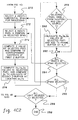
- Continuing with the third pass processing (PASS 2i+1) of FIG. 4C1, scan conversion of edges into a series of horizontal spans next occurs, 268 "Scan Convert Edges Into Series of Horizontal Spans." This involves computation of the Bresenham parameters or DDA slopes for scan converting the triangle edges to produce X,Y,Z,R,G,B,Xs,Ys & Zs, and then scan converting of the triangle edges into the end points of a series of horizontal (or alternatively vertical) spans.
- A pixel X position is identified by first selecting a horizontal span for processing, 270 "Select A (Next) Horizontal Span For Processing," and then selecting a pixel position within that span, 272 "Select A (Next) Pixel X Position In Selected Span." The Z value of the selected pixel is then computed and compared to the contents of the viewpoint depth buffer, 274 "Compute Z Value of Selected Pixel and Compare To Corresponding Contents of First Z-Buffer." Next, the Xs,Ys,Zs values of the selected pixel are computed/interpolated and the calculated Zs value is compared to the contents of the second Z-buffer at location Xs,Ys, 276 "Compute Xs,Ys,Zs Values of Selected Pixel and Compare Zs to Contents of Second Z- Buffer At Location Xs,Ys." Inquiry is then made into whether the selected pixel is visible from both the viewpoint and the subject light source (i), 278 "Is Selected Pixel Visible From Viewpoint and Light Source (i)?" If "yes," then the Rs,Gs,Bs values of the selected pixel are calculated and added to the frame buffer at X,Y, 280 "Calculate Rs,Gs,Bs Values of Selected Pixel and Add to Frame Buffer At X,Y." In other words, if the pixel is visible to both the eyepoint and the selected light source, then intensity values for the pixel are determined and added to the contents of the frame buffer at X,Y.
- If either of the conditions in
inquiry 278 are not met, or if met then after processinginstruction 280, flow is throughjunction 282 toinquiry 284 "All Pixels In Span Selected?" If "no," then processing returns toinstruction 272 where a next pixel X in the selected span is identified for processing. Once all pixels in a span have been processed, then inquiry is made into whether all spans have been processed, 286 "All Spans Selected?" If "no," processing loops back toinstruction 270 where a next horizontal span is selected. Once all pixels and spans have been processed, inquiry is made whether all light sources have been selected, 288 "All Light Sources (i) Selected?" If "no," then processing returns to FIG. 4B atinstruction 230, i.e., select a next defined light source (i) to accomplish PASSES 2i, & 2i+1. Once all light sources have been selected the frame buffer contains the sum of color intensities due to any ambient light and each of the defined light sources (i), including any shadows defined thereby, and processing is terminated, 290 "End." - It will observed form the above discussion that a unique shadow generation approach has been provided capable of efficiently handling multiple light sources. Significantly reduced processing times in comparison with prior shadow rendering techniques are attained, thereby improving user interactiveness with the graphics system. Shadow processing pursuant to the invention attains a performance comparable to non- shadowed, shaded polygons with hidden surfaces removed. The approach is implemented primarily in hardware and maintains a mapping between a viewpoint and a light source by interpolating the respective Z-buffer addresses into dual Z-buffers during span generation. Novel characteristics include the use of 9-axis interpolation instead of the traditional 6-axis, accommodation of multiple light sources through a simple technique of multiple passes over the scene, and correction of depth buffer registration errors by Z displacement in the direction of a light source view gradient in Xs,Ys space (light source view coordinates).
Claims (20)
- A method for rendering a scene formed of at least one geometric primitive as a pixel image with a shadow using a computer graphics display system including a first Z-buffer, a second Z-buffer and a frame buffer, each of said buffers having storage locations corresponding to the pixels forming said image, said image having a defined viewpoint and light source, each primitive being represented by one or more pixels (X,Y) relative to said defined viewpoint and one or more pixels (Xs,Ys) relative to said defined light source, said method comprising the steps of:(a) for each of said pixels (X,Y) representative of said at least one geometric primitive:(i) generating a first depth value (Z) representative of the depth from said defined viewpoint to said pixel, and(ii) saving said first depth value (Z) in the corresponding pixel location of said first Z-buffer if the first depth value (Z) defines a location equal or closer to said viewpoint than a depth value stored in said corresponding pixel location of said first Z-buffer;(b) for each of said pixels (Xs,Ys) representative of said at least one geometric primitive:(i) generating a second depth value (Zs) representative of the depth from said defined light source to said pixel, and(ii) saving said second depth value (Zs) in the corresponding pixel location of said second Z-buffer if the second depth value defines a location (Zs) equal or closer to said light source than a depth value stored in said corresponding pixel location of said second Z-buffer; and(c) for each of said pixels (X,Y) forming said image:(i) generating, using only said defined light source, a representative color value (Rs,Gs,Bs) for said pixel (X,Y), and(ii) adding to a corresponding (X,Y) location of said frame buffer said representative color value (Rs,Gs,Bs) if the corresponding depth value of said first Z-buffer identifies a pixel visible to said viewpoint and the corresponding depth value of said second Z-buffer identifies a pixel visible to said light source.
- The method of claim 1, wherein said image to be rendered has a defined ambient lighting value and wherein said step (a) includes:(iii) generating, using only said ambient lighting value, a representative color value (R,G,B) for said pixel (X,Y) and storing said representative color value (R,G,B) in the corresponding (X,Y) pixel location of said frame buffer.
- The method of claim 2, wherein said at least one geometric primitive is defined by a data structure of one or more polygons and wherein said generating step (a) (iii) includes scan converting said polygons into a series of pixel spans and placing for each span said representative color value (R,G,B) from the end values of said span for each pixel in said span.
- The method of claim 1, wherein a plurality N of light sources are defined and each primitive is represented by one or more pixels (Xs,Ys) (s=1,2...N) relative to each of said N defined light sources, and wherein said method further comprises the steps of repeating said steps (b) and (c) in combination for each of said N defined light sources, said second Z-buffer being cleared prior to each combined repetition of said steps (b) and (c).
- The method of claim 1, wherein each of said at least one geometric primitive is defined in a data structure by one or more polygons and wherein said generating step (a)(i) includes scan converting said polygons into a series of pixel spans and interpolating for each span from the end values of said span said first depth value (Z) for each pixel in said span.
- The method of claim 1, wherein each of said at least one geometric primitive is defined in a data structure by one or more polygons and wherein said generating step (b)(i) includes scan converting said polygons into a series of pixel spans and interpolating for each span from the end values of said span said second depth value (Zs) for each pixel in said span.
- The method of claim 1, wherein said at least one geometric primitive is defined by a data structure of one or more polygons and said generating step (c)(i) includes scan converting said polygons into a series of pixel spans and interpolating for each span said representative color value (Rs,Gs,Bs) from the end values of said span for each pixel in said span.
- The method of claim 1, wherein said at least one geometric primitive is defined by a data structure of one or more polygons, said polygons being defined by their vertices, and wherein said generating step (b)(i) includes adjusting the second depth value (Zs) at each of said polygon vertices relative to said light source to substantially eliminate any misregistration between said one or more pixels (X,Y) relative to said defined viewpoint and said one or more pixels (Xs,Ys) relative to said defined light source.
- The method of claim 1, wherein the order of said steps (a) and (b) is interchanged.
- A method for rendering a scene formed of at least one geometric primitive as a pixel image with a shadow, said at least one geometric primitive being defined by a data structure, said method using a computer graphics display system having a geometry processing engine and a raster processing engine and further including a first Z-buffer, a second Z-buffer and a frame buffer, each of said buffers being coupled to said raster processing engine and each having storage locations corresponding to the pixels forming said image, said image having a defined ambient lighting value, viewpoint and light source such that each primitive has one or more pixels (X,Y) associated therewith in a first, viewpoint coordinate space, and each primitive has one or more pixels (Xs,Ys) associated therewith in a second, light source coordinate space, said method comprising the steps of:(a) processing said data structure through said geometry processing engine and said raster processing engine of said computer graphics display system so as for each of said one or more pixels (X,Y), said engines:(i) generate a first depth value (Z) representative of the distance from said defined viewpoint to said pixel,(ii) save said first depth value (Z) in the corresponding pixel location of said first Z-buffer if the first depth value (Z) is equal or closer to said viewpoint than a depth value stored in said corresponding (X,Y) pixel location of said first Z-buffer, and(iii) determine, using only said ambient lighting, a representative color value (R,G,B) for said pixel and store said determined representative color value (R,G,B) at the corresponding (X,Y) pixel location of said frame buffer;(b) processing said data structure through said geometry processing engine and said raster processing engine of said computer graphics display system so as for each of said one or more pixels (Xs,Ys) said engines:(i) generate a second depth value (Zs) representative of the distance from said defined light source to said pixel, and(ii) save said second depth value (Zs) in the corresponding pixel location of said second Z-buffer if the second depth value (Zs) is equal or closer to said light source than a depth value stored in said corresponding (Xs,Ys) pixel location of said Z-buffer; and(c) processing said data structure through said geometry processing engine and said raster processing engine of said computer graphics display system so as for each pixel (X,Y) of said pixel image, said engines:(i) calculate, using only said defined light source, a representative color value (Rs,Gs,Bs) for said pixel, and(ii) add to the corresponding (X,Y) pixel location of said frame buffer said corresponding representative color value (Rs,Gs,Bs) if the corresponding depth value of said first Z-buffer identifies a visible pixel in said viewpoint coordinate space and the corresponding depth value of said second Z-buffer identifies a visible pixel in said light source coordinate space.
- The method of claim 10, wherein said pixel image has multiple defined light sources associated therewith, each of said light sources defining a separate light source view coordinate space, and wherein said method further includes repeating said steps (b) and (c) in combination for each of said multiple light sources such that for each pixel said frame buffer contains the cumulative color intensities due to said ambient lighting and said multiple defined light sources.
- The method of claim 10, wherein each of said at least one geometric primitive is defined in said data structure by one or more polygons and wherein prior to said first data structure processing step (a) a viewpoint transformation matrix Mv is created, said generate step (a)(i) including for each primitive transforming the associated polygons to device coordinates using said created matrix Mv, scan converting the edges thereof into a series of pixel spans, and interpolating from the end values of said spans said first depth value (Z).
- The method of claim 10, wherein each of said at least one geometric primitive is defined in said data structure by one or more polygons and wherein prior to said second data structure processing step (b) a light source transformation matrix Mi is created, said generate step (b)(i) including for each primitive transforming the associated polygons to device coordinates using said matrix Mi, scan converting the edges thereof into a series of pixel spans, and interpolating from the end values of said spans said first depth values (Z).
- The method of claim 10, wherein each of said at least one geometric primitive is defined in said data structure by one or more polygons and wherein said calculate step (c)(i) includes scan converting said polygons into a series of pixel spans and interpolating for each span said representative color value (Rs,Gs,Bs) from the end values of said span for each pixel in said span.
- The method of claim 10, wherein said at least one geometric primitive is defined in said data structure by one or more polygons, said polygons being defined by their vertices, and wherein said generate step (b)(i) includes adjusting the second depth value (Zs) at each of said polygon vertices relative to said light source to substantially eliminate any misregistration between said one or more pixels (X,Y) in said viewpoint coordinate space and said one or more pixels (Xs,Ys) in said light source coordinate space.
- A computer graphics display system with shadow generation capability for rendering a scene formed of at least one geometric primitive as a pixel image having a defined ambient lighting value, viewpoint and light source such that each primitive has one or more pixels (X,Y) associated therewith in a first, viewpoint coordinate space, and one or more pixels (Xs,Ys) associated therewith in a second, light source coordinate space, said computer graphics display system comprising:
a geometry processing engine for converting said at least one geometric primitive into device X,Y,Z coordinates relative to said viewpoint and into device Xs,Ys,Zs coordinates relative to said light source;
a frame buffer having storage locations corresponding to the pixels forming said image for receiving representative pixel color values;
a first Z-buffer having storage locations corresponding to the pixels forming said image for storing first depth values (Z) representative of the depth of selected pixels (X,Y) in said image relative to said viewpoint;
a second Z-buffer having storage locations corresponding to the pixels forming said image for storing second depth values (Zs) representative of the depth of selected pixels (Xs,Ys) in said image relative to said light source;
a raster processing engine coupled to receive the device coordinates output from said geometry processing engine and coupled to each of said frame buffer, first Z-buffer and second Z-buffer, said raster processing engine including:(i) means for generating for each pixel (X,Y) associated with said at least one geometric primitive a pixel depth value (Z) and for storing said value (Z) in a corresponding (X,Y) location of said first Z-buffer when said pixel depth value (Z) is equal or closer to said viewpoint than a depth value stored in said corresponding location of said first Z-buffer;(ii) means for generating for each pixel (Xs,Ys) associated with said at least one geometric primitive a second pixel depth value (Zs) and for storing said value (Zs) in a corresponding (Xs,Ys) location of said second Z-buffer when said second depth value (Zs) is equal or closer to said light source than a depth value stored in said corresponding location of said second Z-buffer;(iii) means for generating a representative color value (Rs,Gs,Bs) for each pixel forming said image using only said defined light source;(iv) means for adding to a corresponding (X,Y) pixel location of said frame buffer each of said generated representative color values (Rs,Gs,Bs) for said pixels if the corresponding depth value in said first Z-buffer identifies a pixel visible to said viewpoint and the corresponding depth value in said second Z-buffer identifies a pixel visible to said light source. - The computer graphics display system of claim 16, wherein said raster processing engine further includes:
means for generating a representative color value (R,G,B) for each pixel forming said image using only said ambient lighting value; and
means for adding to a corresponding (X,Y) pixel location of said frame buffer each of said generated representative color values (R,G,B) for said pixels at the corresponding (X,Y) pixel location of said frame buffer. - The computer graphics display system of claim 16, wherein said raster processing engine generating means (i) includes:
means for scan converting said at least one geometric primitive into a series of pixel spans; and
means for interpolating said first depth value (Z) for each pixel in said span from the end values of said span. - The computer graphics display system of claim 16, wherein said raster processing engine generating means (ii) includes:
means for scan converting said at least one geometric primitive into a series of pixel spans; and
means for interpolating said second depth value (Zs) for each pixel in said span from the end values of said span. - The computer graphics display system of claim 16, wherein said raster processing engine generating means (iii) includes:
means for scan converting said at least one geometric primitive into a series of pixel spans; and
means for interpolating said representative color value (Rs,Gs,Bs) for each pixel in said span from the end values of said span.
Applications Claiming Priority (2)
| Application Number | Priority Date | Filing Date | Title |
|---|---|---|---|
| US827232 | 1992-01-29 | ||
| US07/827,232 US5377313A (en) | 1992-01-29 | 1992-01-29 | Computer graphics display method and system with shadow generation |
Publications (2)
| Publication Number | Publication Date |
|---|---|
| EP0553973A2 true EP0553973A2 (en) | 1993-08-04 |
| EP0553973A3 EP0553973A3 (en) | 1994-05-18 |
Family
ID=25248652
Family Applications (1)
| Application Number | Title | Priority Date | Filing Date |
|---|---|---|---|
| EP19930300280 Withdrawn EP0553973A3 (en) | 1992-01-29 | 1993-01-18 | Computer graphics display method and system with shadow generation |
Country Status (5)
| Country | Link |
|---|---|
| US (1) | US5377313A (en) |
| EP (1) | EP0553973A3 (en) |
| JP (1) | JPH0683979A (en) |
| KR (1) | KR970003325B1 (en) |
| CA (1) | CA2087501A1 (en) |
Cited By (10)
| Publication number | Priority date | Publication date | Assignee | Title |
|---|---|---|---|---|
| EP0731424A1 (en) * | 1995-03-09 | 1996-09-11 | Sharp Kabushiki Kaisha | Z buffer hidden surface removal device |
| GB2312141A (en) * | 1996-04-11 | 1997-10-15 | Discreet Logic Inc | Generating areas of shadow in 2d image of 3d world |
| EP0840257A2 (en) * | 1996-10-29 | 1998-05-06 | Lockheed Martin Corporation | Illumination and shadow simulation in a computer graphics/imaging system |
| GB2350993A (en) * | 1998-12-15 | 2000-12-13 | Ibm | Generation of mixed semitransparent and opaque objects on a computer display screen. |
| US6204856B1 (en) | 1997-08-01 | 2001-03-20 | U.S. Philips Corporation | Attribute interpolation in 3D graphics |
| EP1229499A2 (en) * | 2001-02-06 | 2002-08-07 | Sony Computer Entertainment America Inc. | System and method for creating real-time shadows of transparent objects |
| US6501481B1 (en) | 1998-07-28 | 2002-12-31 | Koninklijke Philips Electronics N.V. | Attribute interpolation in 3D graphics |
| CN102737401A (en) * | 2011-05-06 | 2012-10-17 | 新奥特(北京)视频技术有限公司 | Triangular plate filling method in rasterization phase in graphic rendering |
| US9342817B2 (en) | 2011-07-07 | 2016-05-17 | Sony Interactive Entertainment LLC | Auto-creating groups for sharing photos |
| US10786736B2 (en) | 2010-05-11 | 2020-09-29 | Sony Interactive Entertainment LLC | Placement of user information in a game space |
Families Citing this family (83)
| Publication number | Priority date | Publication date | Assignee | Title |
|---|---|---|---|---|
| WO1993000650A1 (en) | 1991-06-28 | 1993-01-07 | Hong Lip Lim | Improvements in visibility calculations for 3d computer graphics |
| IL109462A0 (en) * | 1993-04-30 | 1994-07-31 | Scitex Corp Ltd | Method for generating artificial shadow |
| AU6783594A (en) * | 1993-05-10 | 1994-12-12 | Apple Computer, Inc. | Computer graphics system having high performance multiple layer z-buffer |
| US5729672A (en) * | 1993-07-30 | 1998-03-17 | Videologic Limited | Ray tracing method and apparatus for projecting rays through an object represented by a set of infinite surfaces |
| GB9315852D0 (en) * | 1993-07-30 | 1993-09-15 | Video Logic Ltd | Shading three-dimensional images |
| US5821941A (en) * | 1994-08-12 | 1998-10-13 | Dassault Systemes Of America, Corp. | Geometric constraints between related elements in different 2-dimensional views |
| EP0697679A3 (en) * | 1994-08-12 | 1998-07-01 | Dassault Systemes of America | Computerized drawing method |
| US5615321A (en) * | 1994-08-12 | 1997-03-25 | Dassault Systemes Of America Corp. | Automatic identification of geometric relationships between elements of a computer-generated drawing |
| JP3252623B2 (en) * | 1994-11-09 | 2002-02-04 | 松下電器産業株式会社 | Shape model generator |
| JP3570576B2 (en) * | 1995-06-19 | 2004-09-29 | 株式会社日立製作所 | 3D image synthesis and display device compatible with multi-modality |
| US5864342A (en) * | 1995-08-04 | 1999-01-26 | Microsoft Corporation | Method and system for rendering graphical objects to image chunks |
| US5870097A (en) | 1995-08-04 | 1999-02-09 | Microsoft Corporation | Method and system for improving shadowing in a graphics rendering system |
| US5761400A (en) * | 1995-08-28 | 1998-06-02 | Apple Computer, Inc. | Method and system for increasing the speed of a Z-buffer process |
| US5748863A (en) * | 1995-10-06 | 1998-05-05 | International Business Machines Corporation | Method and system for fast interpolation of depth buffer values in a computer graphics display system |
| JP3099940B2 (en) * | 1995-12-25 | 2000-10-16 | 日本電気株式会社 | 3D graphics controller |
| US5739819A (en) * | 1996-02-05 | 1998-04-14 | Scitex Corporation Ltd. | Method and apparatus for generating an artificial shadow in a two dimensional color image |
| US5844566A (en) * | 1996-02-12 | 1998-12-01 | Dassault Systemes | Method and apparatus for controlling shadow geometry on computer displays |
| US5774111A (en) * | 1996-02-12 | 1998-06-30 | Dassault Systemes | Method and apparatus for providing a dynamically oriented compass cursor on computer displays |
| GB9611939D0 (en) * | 1996-06-07 | 1996-08-07 | Philips Electronics Nv | Stereoscopic image display driver apparatus |
| US6104842A (en) * | 1996-06-10 | 2000-08-15 | Integrated Device Technology, Inc. | Geometry processing of digital video models and images |
| US6046746A (en) * | 1996-07-01 | 2000-04-04 | Sun Microsystems, Inc. | Method and apparatus implementing high resolution rendition of Z-buffered primitives |
| US5936629A (en) * | 1996-11-20 | 1999-08-10 | International Business Machines Corporation | Accelerated single source 3D lighting mechanism |
| CA2227531C (en) * | 1997-01-20 | 2003-03-18 | Hitachi, Ltd. | Graphics processing unit and graphics processing system |
| US7616198B2 (en) * | 1998-02-20 | 2009-11-10 | Mental Images Gmbh | System and computer-implemented method for modeling the three-dimensional shape of an object by shading of a two-dimensional image of the object |
| DE19714915A1 (en) * | 1997-04-03 | 1998-10-08 | Gmd Gmbh | Image display method and device for carrying out the method |
| US5933156A (en) * | 1997-12-03 | 1999-08-03 | Margolin; Jed | Z-Buffer for row addressable graphics memory with flash fill |
| US6369816B1 (en) * | 1998-11-12 | 2002-04-09 | Terarecon, Inc. | Method for modulating volume samples using gradient magnitudes and complex functions over a range of values |
| US6356265B1 (en) * | 1998-11-12 | 2002-03-12 | Terarecon, Inc. | Method and apparatus for modulating lighting with gradient magnitudes of volume data in a rendering pipeline |
| US6411296B1 (en) * | 1998-11-12 | 2002-06-25 | Trrarecon, Inc. | Method and apparatus for applying modulated lighting to volume data in a rendering pipeline |
| US6426749B1 (en) * | 1998-11-12 | 2002-07-30 | Terarecon, Inc. | Method and apparatus for mapping reflectance while illuminating volume data in a rendering pipeline |
| US20020190984A1 (en) * | 1999-10-01 | 2002-12-19 | Larry D. Seiler | Voxel and sample pruning in a parallel pipelined volume rendering system |
| US6717577B1 (en) | 1999-10-28 | 2004-04-06 | Nintendo Co., Ltd. | Vertex cache for 3D computer graphics |
| US6618048B1 (en) | 1999-10-28 | 2003-09-09 | Nintendo Co., Ltd. | 3D graphics rendering system for performing Z value clamping in near-Z range to maximize scene resolution of visually important Z components |
| US6670958B1 (en) * | 2000-05-26 | 2003-12-30 | Ati International, Srl | Method and apparatus for routing data to multiple graphics devices |
| US7119813B1 (en) | 2000-06-02 | 2006-10-10 | Nintendo Co., Ltd. | Variable bit field encoding |
| CA2315302A1 (en) * | 2000-07-13 | 2002-01-13 | Paul A. Halmshaw | Three dimensional imaging system |
| US6867781B1 (en) | 2000-08-23 | 2005-03-15 | Nintendo Co., Ltd. | Graphics pipeline token synchronization |
| US7002591B1 (en) | 2000-08-23 | 2006-02-21 | Nintendo Co., Ltd. | Method and apparatus for interleaved processing of direct and indirect texture coordinates in a graphics system |
| US6811489B1 (en) | 2000-08-23 | 2004-11-02 | Nintendo Co., Ltd. | Controller interface for a graphics system |
| US6980218B1 (en) | 2000-08-23 | 2005-12-27 | Nintendo Co., Ltd. | Method and apparatus for efficient generation of texture coordinate displacements for implementing emboss-style bump mapping in a graphics rendering system |
| US6707458B1 (en) | 2000-08-23 | 2004-03-16 | Nintendo Co., Ltd. | Method and apparatus for texture tiling in a graphics system |
| US6937245B1 (en) | 2000-08-23 | 2005-08-30 | Nintendo Co., Ltd. | Graphics system with embedded frame buffer having reconfigurable pixel formats |
| US7184059B1 (en) | 2000-08-23 | 2007-02-27 | Nintendo Co., Ltd. | Graphics system with copy out conversions between embedded frame buffer and main memory |
| US6700586B1 (en) | 2000-08-23 | 2004-03-02 | Nintendo Co., Ltd. | Low cost graphics with stitching processing hardware support for skeletal animation |
| US6664962B1 (en) | 2000-08-23 | 2003-12-16 | Nintendo Co., Ltd. | Shadow mapping in a low cost graphics system |
| US6825851B1 (en) | 2000-08-23 | 2004-11-30 | Nintendo Co., Ltd. | Method and apparatus for environment-mapped bump-mapping in a graphics system |
| US6636214B1 (en) | 2000-08-23 | 2003-10-21 | Nintendo Co., Ltd. | Method and apparatus for dynamically reconfiguring the order of hidden surface processing based on rendering mode |
| US7538772B1 (en) | 2000-08-23 | 2009-05-26 | Nintendo Co., Ltd. | Graphics processing system with enhanced memory controller |
| US7034828B1 (en) | 2000-08-23 | 2006-04-25 | Nintendo Co., Ltd. | Recirculating shade tree blender for a graphics system |
| US7576748B2 (en) | 2000-11-28 | 2009-08-18 | Nintendo Co. Ltd. | Graphics system with embedded frame butter having reconfigurable pixel formats |
| US7196710B1 (en) | 2000-08-23 | 2007-03-27 | Nintendo Co., Ltd. | Method and apparatus for buffering graphics data in a graphics system |
| US7061502B1 (en) | 2000-08-23 | 2006-06-13 | Nintendo Co., Ltd. | Method and apparatus for providing logical combination of N alpha operations within a graphics system |
| US7103677B2 (en) * | 2000-12-06 | 2006-09-05 | Microsoft Corporation | Methods and systems for efficiently processing compressed and uncompressed media content |
| US7114161B2 (en) | 2000-12-06 | 2006-09-26 | Microsoft Corporation | System and related methods for reducing memory requirements of a media processing system |
| US6882891B2 (en) * | 2000-12-06 | 2005-04-19 | Microsoft Corporation | Methods and systems for mixing digital audio signals |
| US6983466B2 (en) | 2000-12-06 | 2006-01-03 | Microsoft Corporation | Multimedia project processing systems and multimedia project processing matrix systems |
| US6961943B2 (en) | 2000-12-06 | 2005-11-01 | Microsoft Corporation | Multimedia processing system parsing multimedia content from a single source to minimize instances of source files |
| US6954581B2 (en) * | 2000-12-06 | 2005-10-11 | Microsoft Corporation | Methods and systems for managing multiple inputs and methods and systems for processing media content |
| US6959438B2 (en) | 2000-12-06 | 2005-10-25 | Microsoft Corporation | Interface and related methods for dynamically generating a filter graph in a development system |
| US6834390B2 (en) * | 2000-12-06 | 2004-12-21 | Microsoft Corporation | System and related interfaces supporting the processing of media content |
| US6912717B2 (en) | 2000-12-06 | 2005-06-28 | Microsoft Corporation | Methods and systems for implementing dynamic properties on objects that support only static properties |
| US7114162B2 (en) | 2000-12-06 | 2006-09-26 | Microsoft Corporation | System and methods for generating and managing filter strings in a filter graph |
| US7447754B2 (en) | 2000-12-06 | 2008-11-04 | Microsoft Corporation | Methods and systems for processing multi-media editing projects |
| US6768499B2 (en) | 2000-12-06 | 2004-07-27 | Microsoft Corporation | Methods and systems for processing media content |
| US7287226B2 (en) * | 2000-12-06 | 2007-10-23 | Microsoft Corporation | Methods and systems for effecting video transitions represented by bitmaps |
| US6774919B2 (en) | 2000-12-06 | 2004-08-10 | Microsoft Corporation | Interface and related methods for reducing source accesses in a development system |
| KR100454070B1 (en) * | 2001-01-31 | 2004-10-20 | 학교법인 중앙대학교 | Method for Real-time Toon Rendering with Shadow using computer |
| AUPS028702A0 (en) * | 2002-02-01 | 2002-02-28 | Canon Kabushiki Kaisha | Efficient display update from changing object graphics |
| JP4193979B2 (en) * | 2003-03-17 | 2008-12-10 | 任天堂株式会社 | Shadow volume generation program and game device |
| US6967663B1 (en) * | 2003-09-08 | 2005-11-22 | Nvidia Corporation | Antialiasing using hybrid supersampling-multisampling |
| JP2005100176A (en) * | 2003-09-25 | 2005-04-14 | Sony Corp | Image processor and its method |
| KR100520707B1 (en) * | 2003-10-20 | 2005-10-17 | 엘지전자 주식회사 | Method for displaying multi-level text data in three dimensional map |
| US7567248B1 (en) * | 2004-04-28 | 2009-07-28 | Mark William R | System and method for computing intersections between rays and surfaces |
| US7525543B2 (en) * | 2004-08-09 | 2009-04-28 | Siemens Medical Solutions Usa, Inc. | High performance shading of large volumetric data using screen-space partial derivatives |
| US7626591B2 (en) * | 2006-01-24 | 2009-12-01 | D & S Consultants, Inc. | System and method for asynchronous continuous-level-of-detail texture mapping for large-scale terrain rendering |
| GB0613352D0 (en) * | 2006-07-05 | 2006-08-16 | Ashbey James A | Improvements in stereoscopic imaging systems |
| US8355022B2 (en) * | 2008-11-25 | 2013-01-15 | Sony Computer Entertainment America Llc | Method and apparatus for aggregating light sources per-vertex in computer graphics |
| US20100128038A1 (en) * | 2008-11-25 | 2010-05-27 | Sony Computer Entertainment America Inc. | Method and apparatus for interpolating color and direction as one entity in computer graphics |
| EP2234069A1 (en) * | 2009-03-27 | 2010-09-29 | Thomson Licensing | Method for generating shadows in an image |
| US8643701B2 (en) | 2009-11-18 | 2014-02-04 | University Of Illinois At Urbana-Champaign | System for executing 3D propagation for depth image-based rendering |
| US9300946B2 (en) | 2011-07-08 | 2016-03-29 | Personify, Inc. | System and method for generating a depth map and fusing images from a camera array |
| US9449118B2 (en) * | 2011-09-29 | 2016-09-20 | Siemens Product Lifecycle Management Software Inc. | Hybrid hidden-line processor and method |
| KR20140142863A (en) * | 2013-06-05 | 2014-12-15 | 한국전자통신연구원 | Apparatus and method for providing graphic editors |
Family Cites Families (14)
| Publication number | Priority date | Publication date | Assignee | Title |
|---|---|---|---|---|
| US4625289A (en) * | 1985-01-09 | 1986-11-25 | Evans & Sutherland Computer Corp. | Computer graphics system of general surface rendering by exhaustive sampling |
| US4737921A (en) * | 1985-06-03 | 1988-04-12 | Dynamic Digital Displays, Inc. | Three dimensional medical image display system |
| US4855938A (en) * | 1987-10-30 | 1989-08-08 | International Business Machines Corporation | Hidden line removal method with modified depth buffer |
| JP3005981B2 (en) * | 1988-07-14 | 2000-02-07 | ダイキン工業株式会社 | Shadow processing method and apparatus |
| US5083287A (en) * | 1988-07-14 | 1992-01-21 | Daikin Industries, Inc. | Method and apparatus for applying a shadowing operation to figures to be drawn for displaying on crt-display |
| JPH0727581B2 (en) * | 1988-09-09 | 1995-03-29 | インターナショナル・ビジネス・マシーンズ・コーポレーション | Graphic processing device |
| US5222203A (en) * | 1989-01-20 | 1993-06-22 | Daikin Industries, Ltd. | Method and apparatus for displaying translucent surface |
| US5027292A (en) * | 1989-04-19 | 1991-06-25 | International Business Machines Corporation | Multiple depth buffers for graphics and solid modelling |
| JPH03127287A (en) * | 1989-10-13 | 1991-05-30 | Nec Corp | Three-dimensional picture generating device |
| US5265198A (en) * | 1989-10-23 | 1993-11-23 | International Business Machines Corporation | Method and processor for drawing `polygon with edge`-type primitives in a computer graphics display system |
| US5123085A (en) * | 1990-03-19 | 1992-06-16 | Sun Microsystems, Inc. | Method and apparatus for rendering anti-aliased polygons |
| US5175805A (en) * | 1990-10-30 | 1992-12-29 | Sun Microsystems, Inc. | Method and apparatus for sequencing composite operations of pixels |
| US5268996A (en) * | 1990-12-20 | 1993-12-07 | General Electric Company | Computer image generation method for determination of total pixel illumination due to plural light sources |
| US5265199A (en) * | 1991-05-22 | 1993-11-23 | Silicon Graphics, Inc. | Method and apparatus for accomplishing Z-buffering by prediction |
-
1992
- 1992-01-29 US US07/827,232 patent/US5377313A/en not_active Expired - Fee Related
-
1993
- 1993-01-18 CA CA002087501A patent/CA2087501A1/en not_active Abandoned
- 1993-01-18 EP EP19930300280 patent/EP0553973A3/en not_active Withdrawn
- 1993-01-22 JP JP5009004A patent/JPH0683979A/en active Pending
- 1993-01-27 KR KR1019930000992A patent/KR970003325B1/en active IP Right Grant
Non-Patent Citations (3)
| Title |
|---|
| COMPUTER GRAPHICS vol. 4, no. 1 , January 1984 , NEW-YORK U.S. pages 5 - 12 BROTMAN AND BADLER 'GENERATING SOFT SHADOWS WITH A DEPTH BUFFER ALGORITHM' * |
| COMPUTERS AND GRAPHICS. vol. 9, no. 3 , 1985 , OXFORD GB pages 259 - 265 HOURCADE AND NICOLAS 'ALGORITHMS FOR ANTIALIASED CAST SHADOWS' * |
| IEEE COMPUTER GRAPHICS AND APPLICATIONS. vol. 9, no. 2 , March 1989 , NEW YORK US pages 30 - 38 XP115874 ROBERTSON 'SPATIAL TRANSFORMATIONS FOR RAPID SCAN-LINE SURFACE SHADOWING' * |
Cited By (19)
| Publication number | Priority date | Publication date | Assignee | Title |
|---|---|---|---|---|
| US5896134A (en) * | 1995-03-09 | 1999-04-20 | Sharp Kabushiki Kaisha | Z buffer hidden surface removal device |
| EP0731424A1 (en) * | 1995-03-09 | 1996-09-11 | Sharp Kabushiki Kaisha | Z buffer hidden surface removal device |
| GB2312141A (en) * | 1996-04-11 | 1997-10-15 | Discreet Logic Inc | Generating areas of shadow in 2d image of 3d world |
| GB2312141B (en) * | 1996-04-11 | 1998-04-22 | Discreet Logic Inc | Processing image data |
| EP0840257A3 (en) * | 1996-10-29 | 2000-12-20 | Lockheed Martin Corporation | Illumination and shadow simulation in a computer graphics/imaging system |
| EP0840257A2 (en) * | 1996-10-29 | 1998-05-06 | Lockheed Martin Corporation | Illumination and shadow simulation in a computer graphics/imaging system |
| US6018350A (en) * | 1996-10-29 | 2000-01-25 | Real 3D, Inc. | Illumination and shadow simulation in a computer graphics/imaging system |
| US6204856B1 (en) | 1997-08-01 | 2001-03-20 | U.S. Philips Corporation | Attribute interpolation in 3D graphics |
| US6501481B1 (en) | 1998-07-28 | 2002-12-31 | Koninklijke Philips Electronics N.V. | Attribute interpolation in 3D graphics |
| GB2350993A (en) * | 1998-12-15 | 2000-12-13 | Ibm | Generation of mixed semitransparent and opaque objects on a computer display screen. |
| GB2350993B (en) * | 1998-12-15 | 2002-12-04 | Ibm | Generation of representations of mixed semitransparent and opaque objects on a computer display screen |
| US7453458B1 (en) | 1998-12-15 | 2008-11-18 | International Business Machines Corporation | Drawing method and drawing apparatus for displaying image data about a plurality of objects including semitransparent object and opaque object on computer display screen |
| US7834879B2 (en) | 1998-12-15 | 2010-11-16 | International Business Machines Corporation | Drawing apparatus for displaying image data about a plurality of objects including semitransparent object and opaque object on computer display screen |
| EP1229499A2 (en) * | 2001-02-06 | 2002-08-07 | Sony Computer Entertainment America Inc. | System and method for creating real-time shadows of transparent objects |
| EP1229499A3 (en) * | 2001-02-06 | 2004-05-19 | Sony Computer Entertainment Inc. | System and method for creating real-time shadows of transparent objects |
| US10786736B2 (en) | 2010-05-11 | 2020-09-29 | Sony Interactive Entertainment LLC | Placement of user information in a game space |
| US11478706B2 (en) | 2010-05-11 | 2022-10-25 | Sony Interactive Entertainment LLC | Placement of user information in a game space |
| CN102737401A (en) * | 2011-05-06 | 2012-10-17 | 新奥特(北京)视频技术有限公司 | Triangular plate filling method in rasterization phase in graphic rendering |
| US9342817B2 (en) | 2011-07-07 | 2016-05-17 | Sony Interactive Entertainment LLC | Auto-creating groups for sharing photos |
Also Published As
| Publication number | Publication date |
|---|---|
| JPH0683979A (en) | 1994-03-25 |
| KR970003325B1 (en) | 1997-03-17 |
| US5377313A (en) | 1994-12-27 |
| CA2087501A1 (en) | 1993-07-30 |
| KR930016909A (en) | 1993-08-30 |
| EP0553973A3 (en) | 1994-05-18 |
Similar Documents
| Publication | Publication Date | Title |
|---|---|---|
| US5377313A (en) | Computer graphics display method and system with shadow generation | |
| US5704024A (en) | Method and an apparatus for generating reflection vectors which can be unnormalized and for using these reflection vectors to index locations on an environment map | |
| KR100504421B1 (en) | Method and apparatus for attribute interpolation in 3d graphics | |
| US6567083B1 (en) | Method, system, and computer program product for providing illumination in computer graphics shading and animation | |
| CA2232757C (en) | Real-time image rendering with layered depth images | |
| US6690372B2 (en) | System, method and article of manufacture for shadow mapping | |
| US5742749A (en) | Method and apparatus for shadow generation through depth mapping | |
| US7532213B2 (en) | Bicubic surface real time tesselation unit | |
| US6437782B1 (en) | Method for rendering shadows with blended transparency without producing visual artifacts in real time applications | |
| US7362332B2 (en) | System and method of simulating motion blur efficiently | |
| Bala et al. | Combining edges and points for interactive high-quality rendering | |
| JP5188628B2 (en) | Method and system for rendering a 3D model of a 3D object | |
| Aliaga | Visualization of complex models using dynamic texture-based simplification | |
| US6532013B1 (en) | System, method and article of manufacture for pixel shaders for programmable shading | |
| US6593923B1 (en) | System, method and article of manufacture for shadow mapping | |
| US7106325B2 (en) | System and method for rendering digital images having surface reflectance properties | |
| US6384824B1 (en) | Method, system and computer program product for multi-pass bump-mapping into an environment map | |
| US7889208B1 (en) | Z-texture mapping system, method and computer program product | |
| US7158133B2 (en) | System and method for shadow rendering | |
| US20020030681A1 (en) | Method for efficiently calculating texture coordinate gradient vectors | |
| US20010048444A1 (en) | System and method for fast phong shading | |
| EP0727764A1 (en) | 3D graphics apparatus | |
| JP4209129B2 (en) | How to render a mesh with multiple polygons representing a graphics model | |
| US6690369B1 (en) | Hardware-accelerated photoreal rendering | |
| Hormann et al. | A quadrilateral rendering primitive |
Legal Events
| Date | Code | Title | Description |
|---|---|---|---|
| PUAI | Public reference made under article 153(3) epc to a published international application that has entered the european phase |
Free format text: ORIGINAL CODE: 0009012 |
|
| AK | Designated contracting states |
Kind code of ref document: A2 Designated state(s): AT BE CH DE ES FR GB IT LI NL SE |
|
| 17P | Request for examination filed |
Effective date: 19931119 |
|
| PUAL | Search report despatched |
Free format text: ORIGINAL CODE: 0009013 |
|
| AK | Designated contracting states |
Kind code of ref document: A3 Designated state(s): AT BE CH DE ES FR GB IT LI NL SE |
|
| STAA | Information on the status of an ep patent application or granted ep patent |
Free format text: STATUS: THE APPLICATION IS DEEMED TO BE WITHDRAWN |
|
| 18D | Application deemed to be withdrawn |
Effective date: 19960801 |