EP0411962A2 - Control device and method for twin-roll continuous caster - Google Patents
Control device and method for twin-roll continuous caster Download PDFInfo
- Publication number
- EP0411962A2 EP0411962A2 EP90308578A EP90308578A EP0411962A2 EP 0411962 A2 EP0411962 A2 EP 0411962A2 EP 90308578 A EP90308578 A EP 90308578A EP 90308578 A EP90308578 A EP 90308578A EP 0411962 A2 EP0411962 A2 EP 0411962A2
- Authority
- EP
- European Patent Office
- Prior art keywords
- thickness
- cast
- roll
- control device
- separating force
- Prior art date
- Legal status (The legal status is an assumption and is not a legal conclusion. Google has not performed a legal analysis and makes no representation as to the accuracy of the status listed.)
- Granted
Links
Images


Classifications
-
- B—PERFORMING OPERATIONS; TRANSPORTING
- B22—CASTING; POWDER METALLURGY
- B22D—CASTING OF METALS; CASTING OF OTHER SUBSTANCES BY THE SAME PROCESSES OR DEVICES
- B22D11/00—Continuous casting of metals, i.e. casting in indefinite lengths
- B22D11/04—Continuous casting of metals, i.e. casting in indefinite lengths into open-ended moulds
-
- B—PERFORMING OPERATIONS; TRANSPORTING
- B22—CASTING; POWDER METALLURGY
- B22D—CASTING OF METALS; CASTING OF OTHER SUBSTANCES BY THE SAME PROCESSES OR DEVICES
- B22D11/00—Continuous casting of metals, i.e. casting in indefinite lengths
- B22D11/06—Continuous casting of metals, i.e. casting in indefinite lengths into moulds with travelling walls, e.g. with rolls, plates, belts, caterpillars
- B22D11/0622—Continuous casting of metals, i.e. casting in indefinite lengths into moulds with travelling walls, e.g. with rolls, plates, belts, caterpillars formed by two casting wheels
-
- B—PERFORMING OPERATIONS; TRANSPORTING
- B22—CASTING; POWDER METALLURGY
- B22D—CASTING OF METALS; CASTING OF OTHER SUBSTANCES BY THE SAME PROCESSES OR DEVICES
- B22D11/00—Continuous casting of metals, i.e. casting in indefinite lengths
- B22D11/06—Continuous casting of metals, i.e. casting in indefinite lengths into moulds with travelling walls, e.g. with rolls, plates, belts, caterpillars
Definitions
- the present invention relates to a twin-roll continuous caster by which a cast strip can be directly produced from molten metal. More specifically, it relates to a control device and a control method for the twin-roll continuous caster, which device and method enable the production of a cast strip with high-quality surfaces.
- molten metal is continuously supplied into a molten pool defined between a pair of opposed cooling rolls which rotate in opposite directions; on each cooling roll a solidified shell is formed by contact between the molten metal and the cooling roll, and the solidified shells are bonded at the nearest point of contact of rolls (i.e. the nip or kissing point) to thereby produce a cast strip.
- Japanese Unexamined Patent Publication No. 60-64754 discloses a method to eliminate bulging (which occurs during bonding when the roll separating force is low) and to prevent roll slip (which occurs during bonding when the roll separating force is high). Bulging results in an unbonded condition of the shell, causing separation or break out of the cast strip.
- the rolling load of the solidified shells as the force reacting against the roll separating force, is detected, and then the solidification period of the shells between the cooling rolls (which can be representative of either the rotating speed of the cooling rolls or the height of the molten pool) is controlled in such a manner that the rolling load is neither too high nor too low.
- Japanese Unexamined Patent Publication Nos. 59-56950, 60-92051, 61-232044, 61-232045, 61-289950, 62-97749 disclose methods or devices for eliminating bulging.
- This surface crack phenomenon is due to local stress concentration generated in the solidified shells when rolling solidified shells of unequal thickness in the longitudinal direction of the cooling roll.
- the thicker the target thickness of the cast strip or the higher the roll separating force the greater the incidence of continuous surface cracks due to larger variations of thickness of the solidified shell.
- the object of Japanese Unexamined Patent Publication No. 62-97749 is to prevent the occurrence of surface cracks by detecting and controlling the roll separating force, it does not consider the influence of the cast thickness upon the occurrence of surface cracks.
- the present invention provides a control device and a control method for combatting bulging and the occurrence of continuous surface cracks in a twin-roll continuous caster, by considering the influence of the cast thickness.
- a control device for a twin-roll continuous caster including a pair of opposed cooling rolls which rotate in opposite directions, these cooling rolls defining a molten pool therebetween into which molten metal is supplied, and a solidified shell is formed on each cooling roll by a contact between each cooling roll and the molten metal, whereby the solidified shells are bonded at the nearest point of contact of each of the cooling rolls, to thereby continuously produce a cast strip
- said control device comprising; a pluralily of maps prepared prior to the operation of the twin-roll continuous caster and stored in a memory of the control device, each of the maps corresponding to a height of the molten pool and a casting speed, teaching a relationship between a thickness of the cast strip and a roll separating force under a fixed casting speed and a fixed height of the molten pool, and defining stable casting conditions under which bulging and surface cracks do not occur; these conditions consisting of a combination of a specific range of the thickness of a cast strip and a specific
- a control method for a twin-roll continuous caster including a pair of opposed cooling rolls which rotate in opposite directions, said cooling rolls defining a molten pool therebetween into which molten metal is supplied, and a solidified shell is formed on each cooling roll by a contact between each of the cooling rolls with said molten metal, whereby each solidified shell is bonded at the nearest point of contact of each of the cooling rolls, to thereby continuously produce a cast strip
- this control method comprising; preparing a plurality of maps prior to the operation of the twin-roll continuous caster and storing said plurality of maps in a memory of the control device, each of the maps corresponding to a height of the molten pool and a casting speed, teaching a relationship between a thickness of the cast strip and a roll separating force under a fixed casting speed and a fixed height of the molten pool, and defining stable casting conditions under which bulging and surface cracks do not occur, and which consists of a combination of a specific range of the thickness of a cast
- the plurality of maps are memorized prior to the operation of the twin-roll continuous caster, and during the process of obtaining the actual cast thickness for the target value, the present control device controls the casting conditions ,i.e., the casting speed and the roll separating force, in such a manner that the casting operation is executed under specific casting conditions defined by the map as a stable area within which defects such as bulging and surface cracks will not occur.
- Fig. 3 shows the various curves each show the relationship between the cast thickness Ti and the roll separating force P under a fixed casting speed Vc (rotating speed of cooling rolls), at a certain height of the molten pool, which can be expressed as an angle of 40° of the circumference of the cooling roll, assuming that the height at the kissing point thereof corresponds to an angle 0°. Furthermore, Fig. 3 shows three areas of the quality of the cast strip produced under such casting conditions. Namely, according to data obtained by experiments, surface cracks occurred under the casting conditions shown in area A and bulging occurred under the casting conditions shown in area B. Neither surface cracks nor bulging occurred in area C, and thus a cast strip with a stable quality was obtained in this area.
- a control device in accordance with the invention stores a map corresponding to each height of the molten pool as represented in the above-mentioned figure, and during the control of the thickness of the cast strip to a target value, the device controls the casting conditions so that they are within the area C, as shown in Fig. 3, and thus it is possible to cast a cast strip having the target thickness without the occurrence of bulging or surface cracks.
- a molten metal is supplied from a ladle (not shown) into a tundish 1, and then is poured through a nozzle 2 extending downwards from the tundish 1 into a molten pool 5 defined by a pair of cooling rolls 3 and 3′ and a pair of side dams 4 and 4′ pressed against both end surfaces of the cooling rolls 3 and 3′ .
- a refrigerant such as cooling water is charged into the cooling rolls 3 and 3′, to thereby forcibly cool same to control the temperature at the outer surfaces thereof.
- the cooling rolls 3 and 3′ are rotatably supported by a housing 6 and are respectively rotated by a drive motor 7 through the intermediary of a reduction gear device 8 and synchromesh gears 9 and 9′, which cooperate with the cooling rolls 3 and 3′, respectively. Therefore, during casting, each roll 3 or 3′ rotates in a direction opposite to the other, as shown by arrows "a" and "a′”.
- the cooling roll 3′ is supported by the housing 6 in such a manner that the roll 3′ can be moved towards and away from the cooling roll 3.
- the roll 3′ is provided with an actuator 16 such as a hydraulic cylinder by which the roll separating force for the solidified shells 10 and 10′ can be varied.
- the housing 6 is provided with a sensor 17 for detecting the width of the gap 11, i.e., the cast thickness Ti of the cast strip 12. Note that the cast thickness Ti may be calculated by detecting the position of the cooling roll 3′ in the housing 6.
- the drive motors 7 and 15 are electrically connected to a control circuit 18 through the intermediary of a drive circuits 19, and the actuator 16 is electrically connected to the circuit 18 through a drive circuit 20.
- the control circuit 18, which may be constituted by, for example, a microcomputer, comprises an inputport(I/P) 21, an outputport (O/P) 22, a memory 23 having a Random Access Memory (RAM) and a Read Only Memory (ROM), a Microprocessing Unit (MPU) 24, and a bus 25 interconnecting these units.
- the inputport 21 is constituted by an analog input circuit receiving a signal generated from the cast thickness detecting sensor 17, an interface, and an analog/digital converter.
- the outputport 22 generates a variable drive output signal Vc and outputs same to the drive circuit 19, and generates another variable drive output signal P and outputs same to the drive circuit 20.
- the signal from the cast thickness detecting sensor 17 and a signal from a level sensor 26 for detecting the height of the molten pool 5 are input to the inputport 21. Furthermore, a target thickness Ta, which is determined by a specification of the cast strip to be produced, is input to the inputport 21 by an operator.
- the control circuit 18 selects an appropriate map (for example, Fig. 3) from among a plurality of maps prestored in the ROM and corresponding to different heights of the molten pool 5, determines an appropriate roll separating force P and an appropriate casting speed Vc within an area C at which surface cracks and bulging do not occur, generates output signals corresponding to the roll separating force and the casting speed, and outputs same to the drive circuits 19 and 20, respectively.
- an appropriate map for example, Fig. 3
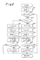
- Figure 2 shows a flow-chart of the operation of the control circuit 18 whereby, by changing the roll separating force P and/or the casting speed Vc, the cast thickness Ti is brought to the target thickness Ta without the occurrence of bulging or surface cracks even if the actual thickness Ti is different from the target thickness Ta.
- the program for executing the above operation is stored in a predetermined area of the ROM of the control circuit 18 and is executed at predetermined intervals during the casting.
- an appropriate map having predetermined values such as ⁇ -max and ⁇ min shown in Fig 3 is selected by the control circuit 18 in accordance with the height of the molten pool 5 detected by the level sensor 26, and the target thickness Ta is stored in the memory 23 prior to the following operation.
- the actual cast thickness Ti of the cast strip 12 is detected by the cast thickness detecting sensor 17, and at step 202, it is determined whether or not the detected thickness Ti is different from the prestored target thickness Ta, i.e., in detail, whether or not the absolute difference between Ti and Ta is greater than the allowable error "e".
- the casting conditions are such that the target thickness Ta is 2.2 mm, the casting speed Vi is 80 m/min. and the roll separating force Pi is 3 ton, if the detected actual thickness Ti is 2.1 mm when the allowable error "e” is 0.05 mm, the result at step 202 will be "Yes", and thus the routine goes to step 203.
- the routine is ended and the following steps are omitted.
- step 203 it is determined whether or not the target thickness Ta is greater than the actual thickness Ti. If the result at step 203 is "Yes", i.e., when the actual thickness Ti is less than the target thickness Ta, as mentioned in the above numerical example, the routine goes to step 204 and the actual roll separating force P is reduced by a predetermined value ⁇ P (e.g., 0.1 ton ) to enable an increase of the actual thickness Ti.
- ⁇ P e.g., 0.1 ton
- the actual thickness as the previous Ti read at step 201 is stored in the memory 23 as the thickness value (before changing the roll separating force), and thereafter, at step 206, the present cast thickness Ti (after change of the roll separating force) is newly detected by the cast thickness detecting sensor 17.
- step 203 when the result at step 203 is NO, i.e., when the detected actual cast thickness Ti is greater than the target thickness Ta, processes similar to the above-mentioned processes from step 204 to step 207 are executed. Namely, at step 210, the actual roll separating force P is increased by a predetermined value ⁇ P (ex. 0.1 ton), to thereby reduce the actual thickness Ti.
- ⁇ P ex. 0.1 ton
- the actual thickness Ti read at step 201 is converted to a value Tib before the change of the roll separating force, and the value Tib is stored in the memory 23 of the control circuit 18.
- the present cast thickness Ti after the change of the roll separating force is newly detected by the cast thickness detecting sensor 17.
- step 208 it is determined whether the calculated "d" at step 207 is more than the minimum value ⁇ min ( ⁇ min ⁇ 0) of the ratio "d" , which is a substantially constant value, independent of the casting speed Vc, obtained by experiments, and which is the slope of the tangent to the cast thickness - roll separating force (Ti-P) curves at crossing points with a boundary line between the area B and the area C in Fig. 3. Namely, at step 208, it is determined whether or not two sheets of solidified shells can be bonded without producing a bulge.
- step 208 If the result at step 208 is "No", since the calculated ratio "d" is less than the minimum value ⁇ min, i.e., if it is determined that the present casting condition is in the area B, then the routine goes to step 209 and the control circuit 18 outputs a signal to the drive circuit 19 so that the casting will be held at a new casting speed (Vc - ⁇ V) which is lower than the present casting speed Vc by a predetermined value ⁇ V (e.g., 5 m/min.).
- ⁇ V e.g., 5 m/min.
- the thickness Ti of the cast strip 12 can be increased while maintaining the same roll separating force P, since the corresponding curve of the cast thickness - roll separating force is shifted upwards due to the reduction of the casting speed. Also, corresponding to this shift, the operation point is moved out of the bulge area B, since the smaller the casting speed the narrower becomes the range at which bulging will occur, as shown in Fig. 3, and this routine is then ended.
- the routine is ended by skipping step 209, and thus at step 202 in the next routine it will be determined whether or not the obtained cast thickness Ti is different from the target thickness Ta.
- the process for reducing the cast thickness is executed at step 210.
- the new casting condition may be in the area A at which surface cracks occur, due to the change of the casting condition, as shown by arrow "n" in Fig. 3.
- step 214 it is determined whether the calculated "d" at step 213 is less than the maximum value ⁇ max ( ⁇ max ⁇ 0) of the ratio "d", which is also substantially a constant value independent of the casting speed Vc obtained from experiments, and which is the slope of the tangent to Ti - P curves at crossing points with a boundary line between the area A and the area B in Fig. 3, similar to the afore-mentioned minimum value ⁇ min. Namely, at step 214, it is determined whether the present casting condition (the casting speed Vc and the roll separating force P) is in the area C at which surface cracks do not occur.
- the present casting condition the casting speed Vc and the roll separating force P
- step 214 If the result at step 214 in "No", i.e., if it is determined that present casting condition is in the area A, then the routine goes to step 215 and the control circuit 18 outputs a signal to the drive circuit 19 to cause the casting to be held at a new casting speed (Vc + ⁇ V), which is higher than the present casting speed Vc by a predetermined value ⁇ V (e.g. 5 m/min.).
- the rotating speeds of the cooling rolls 3 and 3′ and the pinch roll 14 are increased at the same time, and thus the period of solidification of the shells 10 and 10 is reduced. Due to this reduction of the solidification period, the thickness Ti of the cast strip 12 can be reduced while using the same roll separating force P, since the corresponding curve of the cast thickness - roll separating force is shifted downwards in Fig. 3. Further, corresponding to this shift, the operation point is moved out of the bulge area A, since the higher the casting speed Vc the narrower becomes the range in which surface cracks occur, as shown in Fig. 3, and finally, the operation point will be contained in the area C by one or more executions of this routine thereafter.
- the routine is ended by skipping step 215, and thus at step 202 in the next routine it will be determined whether or not the obtained cast thickness Ti is different from the target thickness Ta. If the target thickness Ta cannot be realized, the processes after step 210 are repeatedly executed until the target thickness Ta is finally obtained.
- the maximum value max employed at step 214 is also a constant value independent of the casting speed Vc, obtained from experiments, and each maximum value max is prestored in the memory 23 for each height of the molten pool 5, as well as the aforementioned minimum values ⁇ min.
- control circuit 18 controls the casting conditions, such as the roll separating force and the casting speed, in such a manner that the ratio "d", which can be calculated when controlling the cast thickness, is between the minimum ratio ⁇ min corresponding to a boundary at which bulging occurs and the maximum ratio ⁇ max corresponding a boundary at which surface cracks occur.
- a cast strip with an improved surface quality can be provided since, in the control of thickness of the strip to be cast by the twin-roll continuous caster, the target thickness of the cast strip can be obtained, and the roll separating force and the casting speed controlled to ensure that neither bulging nor surface cracks occur.
Abstract
Description
- The present invention relates to a twin-roll continuous caster by which a cast strip can be directly produced from molten metal. More specifically, it relates to a control device and a control method for the twin-roll continuous caster, which device and method enable the production of a cast strip with high-quality surfaces.
- In the well-known twin-roll casting process, molten metal is continuously supplied into a molten pool defined between a pair of opposed cooling rolls which rotate in opposite directions; on each cooling roll a solidified shell is formed by contact between the molten metal and the cooling roll, and the solidified shells are bonded at the nearest point of contact of rolls (i.e. the nip or kissing point) to thereby produce a cast strip.
- Japanese Unexamined Patent Publication No. 60-64754 discloses a method to eliminate bulging (which occurs during bonding when the roll separating force is low) and to prevent roll slip (which occurs during bonding when the roll separating force is high). Bulging results in an unbonded condition of the shell, causing separation or break out of the cast strip.
- In the above method, the rolling load of the solidified shells, as the force reacting against the roll separating force, is detected, and then the solidification period of the shells between the cooling rolls (which can be representative of either the rotating speed of the cooling rolls or the height of the molten pool) is controlled in such a manner that the rolling load is neither too high nor too low.
- In addition to the above method, Japanese Unexamined Patent Publication Nos. 59-56950, 60-92051, 61-232044, 61-232045, 61-289950, 62-97749 disclose methods or devices for eliminating bulging.
- In general, when solidified shells having a given thickness are bonded at the kissing point, the greater the increase of the roll separating force the stronger the binding strength, but when the roll separating force is higher than a predetermined value, many continuous surface cracks extending in the casting direction are produced in the cast strip.
- This surface crack phenomenon is due to local stress concentration generated in the solidified shells when rolling solidified shells of unequal thickness in the longitudinal direction of the cooling roll. The thicker the target thickness of the cast strip or the higher the roll separating force, the greater the incidence of continuous surface cracks due to larger variations of thickness of the solidified shell. Further, it has been found that surface cracks still occur even when the roll separating force is lower than the roll separating force value at which the afore-mentioned roll slip phenomenon occurs. Therefore, the method of controlling the solidifcation period as disclosed in Japanese Unexamined Patent Publication No. 60-64754 cannot prevent the occurence of continuous surface cracks. Further, although the object of Japanese Unexamined Patent Publication No. 62-97749 is to prevent the occurrence of surface cracks by detecting and controlling the roll separating force, it does not consider the influence of the cast thickness upon the occurrence of surface cracks.
- The present invention provides a control device and a control method for combatting bulging and the occurrence of continuous surface cracks in a twin-roll continuous caster, by considering the influence of the cast thickness.
- According to the present invention, there is provided a control device for a twin-roll continuous caster including a pair of opposed cooling rolls which rotate in opposite directions, these cooling rolls defining a molten pool therebetween into which molten metal is supplied, and a solidified shell is formed on each cooling roll by a contact between each cooling roll and the molten metal, whereby the solidified shells are bonded at the nearest point of contact of each of the cooling rolls, to thereby continuously produce a cast strip said control device comprising;
a pluralily of maps prepared prior to the operation of the twin-roll continuous caster and stored in a memory of the control device, each of the maps corresponding to a height of the molten pool and a casting speed, teaching a relationship between a thickness of the cast strip and a roll separating force under a fixed casting speed and a fixed height of the molten pool, and defining stable casting conditions under which bulging and surface cracks do not occur; these conditions consisting of a combination of a specific range of the thickness of a cast strip and a specific range of the roll separating force; a thickness detecting means for detecting an actual cast thickness of the cast strip being cast; a height detecting means for detecting an actual height of the molten pool; a selecting means for selecting an appropriate map from among the plurality of maps corresponding to the detected actual height of molten pool; and a control means for controlling at least one of the casting speed and the roll separating force in accordance with a difference between the actual cast thickness of the cast strip and an target thickness thereof, in such a manner that the cast strip of the target thickness can be cast under stable casting conditions obtained from the selected appropriate map. - Furthermore, there is provided a control method for a twin-roll continuous caster including a pair of opposed cooling rolls which rotate in opposite directions, said cooling rolls defining a molten pool therebetween into which molten metal is supplied, and a solidified shell is formed on each cooling roll by a contact between each of the cooling rolls with said molten metal, whereby each solidified shell is bonded at the nearest point of contact of each of the cooling rolls, to thereby continuously produce a cast strip, this control method comprising;
preparing a plurality of maps prior to the operation of the twin-roll continuous caster and storing said plurality of maps in a memory of the control device, each of the maps corresponding to a height of the molten pool and a casting speed, teaching a relationship between a thickness of the cast strip and a roll separating force under a fixed casting speed and a fixed height of the molten pool, and defining stable casting conditions under which bulging and surface cracks do not occur, and which consists of a combination of a specific range of the thickness of a cast strip and a specific range of the roll separating force;
detecting an actual cast thickness of the cast strip being cast;
detecting an actual height of the molten pool;
selecting an appropriate map from among plurality of maps corresponding to the detected actual height of molten pool;
controlling at least one of the casting speed and the roll separating force in accordance with a difference between the actual cast thickness of the cast strip and an target thickness thereof; and thereby casting the casting cast strip to the target thickness under the stable casting conditions of the selected appropriate map. - According to the present invention, the plurality of maps are memorized prior to the operation of the twin-roll continuous caster, and during the process of obtaining the actual cast thickness for the target value, the present control device controls the casting conditions ,i.e., the casting speed and the roll separating force, in such a manner that the casting operation is executed under specific casting conditions defined by the map as a stable area within which defects such as bulging and surface cracks will not occur.
- In the accompanying drawings :
- Figure 1 shows the general construction of a twin-roll continuous caster equipped with a control device according to the present invention;
- Fig. 2 is a flow chart executed by the control device to control the casting conditions, according to the present invention; and
- Fig. 3 is a map showing the relationship among the cast thickness, the roll separating force and the quality of the cast strip under various casting speeds and at certain height of the molten pool, which height can be representative of the circumferential angle of 40° from the kissing point.
- An explanation of a map obtained by experiments for use in the present control device is given with reference to Figure 3 .
- In Fig. 3, the various curves each show the relationship between the cast thickness Ti and the roll separating force P under a fixed casting speed Vc (rotating speed of cooling rolls), at a certain height of the molten pool, which can be expressed as an angle of 40° of the circumference of the cooling roll, assuming that the height at the kissing point thereof corresponds to an angle 0°. Furthermore, Fig. 3 shows three areas of the quality of the cast strip produced under such casting conditions. Namely, according to data obtained by experiments, surface cracks occurred under the casting conditions shown in area A and bulging occurred under the casting conditions shown in area B. Neither surface cracks nor bulging occurred in area C, and thus a cast strip with a stable quality was obtained in this area.
- A control device in accordance with the invention stores a map corresponding to each height of the molten pool as represented in the above-mentioned figure, and during the control of the thickness of the cast strip to a target value, the device controls the casting conditions so that they are within the area C, as shown in Fig. 3, and thus it is possible to cast a cast strip having the target thickness without the occurrence of bulging or surface cracks.
- Referring to Fig. 1, a molten metal is supplied from a ladle (not shown) into a tundish 1, and then is poured through a
nozzle 2 extending downwards from the tundish 1 into a molten pool 5 defined by a pair ofcooling rolls side dams cooling rolls - When casting, a refrigerant such as cooling water is charged into the
cooling rolls cooling rolls housing 6 and are respectively rotated by a drive motor 7 through the intermediary of areduction gear device 8 andsynchromesh gears cooling rolls roll - Then , due to the cooling of the
rolls solidified shells rolls shells rolls cast strip 12. Subsequently, thecast strip 12 is drawn downwards bypinch rolls pinch rolls 14 are rotated by adrive motor 15 in synchronization with the rotaing speed of thecooling rolls - The
cooling roll 3′ is supported by thehousing 6 in such a manner that theroll 3′ can be moved towards and away from thecooling roll 3. For this purpose, theroll 3′ is provided with an actuator 16 such as a hydraulic cylinder by which the roll separating force for thesolidified shells - The
housing 6 is provided with asensor 17 for detecting the width of thegap 11, i.e., the cast thickness Ti of thecast strip 12. Note that the cast thickness Ti may be calculated by detecting the position of thecooling roll 3′ in thehousing 6. - The
drive motors 7 and 15 are electrically connected to acontrol circuit 18 through the intermediary of adrive circuits 19, and the actuator 16 is electrically connected to thecircuit 18 through adrive circuit 20. - The
control circuit 18, which may be constituted by, for example, a microcomputer, comprises an inputport(I/P) 21, an outputport (O/P) 22, amemory 23 having a Random Access Memory (RAM) and a Read Only Memory (ROM), a Microprocessing Unit (MPU) 24, and abus 25 interconnecting these units. Theinputport 21 is constituted by an analog input circuit receiving a signal generated from the castthickness detecting sensor 17, an interface, and an analog/digital converter. Theoutputport 22 generates a variable drive output signal Vc and outputs same to thedrive circuit 19, and generates another variable drive output signal P and outputs same to thedrive circuit 20. - The signal from the cast
thickness detecting sensor 17 and a signal from a level sensor 26 for detecting the height of the molten pool 5 are input to theinputport 21. Furthermore, a target thickness Ta, which is determined by a specification of the cast strip to be produced, is input to theinputport 21 by an operator. - In operation, based on the input target thickness Ta and the detected height of the molten pool 5, the control circuit 18 (in particular, the MPU 24) selects an appropriate map (for example, Fig. 3) from among a plurality of maps prestored in the ROM and corresponding to different heights of the molten pool 5, determines an appropriate roll separating force P and an appropriate casting speed Vc within an area C at which surface cracks and bulging do not occur, generates output signals corresponding to the roll separating force and the casting speed, and outputs same to the
drive circuits - Although the casting operation is started under the casting conditions determined as described above, sometimes the actual cast thickness Ti of the
cast strip 12 deviates from the target thickness Ta due to disturbance or variation of the casting conditions per se. Figure 2 shows a flow-chart of the operation of thecontrol circuit 18 whereby, by changing the roll separating force P and/or the casting speed Vc, the cast thickness Ti is brought to the target thickness Ta without the occurrence of bulging or surface cracks even if the actual thickness Ti is different from the target thickness Ta. The program for executing the above operation is stored in a predetermined area of the ROM of thecontrol circuit 18 and is executed at predetermined intervals during the casting. Note that, according to this embodiment, an appropriate map having predetermined values such as α-max and αmin shown in Fig 3 is selected by thecontrol circuit 18 in accordance with the height of the molten pool 5 detected by the level sensor 26, and the target thickness Ta is stored in thememory 23 prior to the following operation. - Referring to Fig. 2, at
step 201,the actual cast thickness Ti of thecast strip 12 is detected by the castthickness detecting sensor 17, and atstep 202, it is determined whether or not the detected thickness Ti is different from the prestored target thickness Ta, i.e., in detail, whether or not the absolute difference between Ti and Ta is greater than the allowable error "e". - Assuming that the casting conditions are such that the target thickness Ta is 2.2 mm, the casting speed Vi is 80 m/min. and the roll separating force Pi is 3 ton, if the detected actual thickness Ti is 2.1 mm when the allowable error "e" is 0.05 mm, the result at
step 202 will be "Yes", and thus the routine goes tostep 203. - On the other hand, if it is determined the actual thickness Ti is substantially the same as the target thickness Ta, i.e., if the difference between Ti and Ta is within the allowable error "e", the routine is ended and the following steps are omitted.
- At
step 203, it is determined whether or not the target thickness Ta is greater than the actual thickness Ti. If the result atstep 203 is "Yes", i.e., when the actual thickness Ti is less than the target thickness Ta, as mentioned in the above numerical example, the routine goes tostep 204 and the actual roll separating force P is reduced by a predetermined value ΔP (e.g., 0.1 ton ) to enable an increase of the actual thickness Ti. - Then, at
step 205, the actual thickness as the previous Ti read atstep 201 is stored in thememory 23 as the thickness value (before changing the roll separating force), and thereafter, atstep 206, the present cast thickness Ti (after change of the roll separating force) is newly detected by the castthickness detecting sensor 17. - Next, at
step 207, the ratio "d" of the variation of the cast thickness relative to variation of the roll separating force atstep 204 is calculated as follows:
d = ( Ti - Tib ) / -ΔP
, where Ti > Tib,
ΔP > 0, and therefore,
d < O - On the other hand, when the result at
step 203 is NO, i.e., when the detected actual cast thickness Ti is greater than the target thickness Ta, processes similar to the above-mentioned processes fromstep 204 to step 207 are executed. Namely, atstep 210, the actual roll separating force P is increased by a predetermined value ΔP (ex. 0.1 ton), to thereby reduce the actual thickness Ti. - Then, at
step 211, the actual thickness Ti read atstep 201 is converted to a value Tib before the change of the roll separating force, and the value Tib is stored in thememory 23 of thecontrol circuit 18. Thereafter, atstep 212, the present cast thickness Ti after the change of the roll separating force is newly detected by the castthickness detecting sensor 17. - Next, at
step 213, the ratio "d" of the variation of the cast thickness relative to variation of the roll separating force found atstep 210 is calculated as follows:
d = ( Ti - Tib )/ ΔP
, where Ti < Tib,
ΔP > 0, and therefore,
d < O - Generally speaking, when the roll separating force P is lowered to increase the cast thickness, as shown by an arrow "m" in Fig. 3, a serious problem arises in that the new casting condition may be included in the bulging area B of Fig. 3, due to the change of the casting condition. Therefore, at
step 208, it is determined whether the calculated "d" atstep 207 is more than the minimum value αmin (αmin < 0) of the ratio "d" , which is a substantially constant value, independent of the casting speed Vc, obtained by experiments, and which is the slope of the tangent to the cast thickness - roll separating force (Ti-P) curves at crossing points with a boundary line between the area B and the area C in Fig. 3. Namely, atstep 208, it is determined whether or not two sheets of solidified shells can be bonded without producing a bulge. - If the result at
step 208 is "No", since the calculated ratio "d" is less than the minimum value αmin, i.e., if it is determined that the present casting condition is in the area B, then the routine goes to step 209 and thecontrol circuit 18 outputs a signal to thedrive circuit 19 so that the casting will be held at a new casting speed (Vc - ΔV) which is lower than the present casting speed Vc by a predetermined value ΔV (e.g., 5 m/min.). - Consequently, the thickness Ti of the
cast strip 12 can be increased while maintaining the same roll separating force P, since the corresponding curve of the cast thickness - roll separating force is shifted upwards due to the reduction of the casting speed. Also, corresponding to this shift, the operation point is moved out of the bulge area B, since the smaller the casting speed the narrower becomes the range at which bulging will occur, as shown in Fig. 3, and this routine is then ended. When the result atstep 208 is "Yes", i.e., when a new casting condition established at this time is in the area C of Fig. 3, the routine is ended by skippingstep 209, and thus atstep 202 in the next routine it will be determined whether or not the obtained cast thickness Ti is different from the target thickness Ta. - Conversely, when the actual cast thickness Ti is larger than the target thickness Ta, the process for reducing the cast thickness is executed at
step 210. Here, however, a new problem may arise in that the new casting condition may be in the area A at which surface cracks occur, due to the change of the casting condition, as shown by arrow "n" in Fig. 3. - Therefore, at
step 214, it is determined whether the calculated "d" atstep 213 is less than the maximum value αmax (αmax < 0) of the ratio "d", which is also substantially a constant value independent of the casting speed Vc obtained from experiments, and which is the slope of the tangent to Ti - P curves at crossing points with a boundary line between the area A and the area B in Fig. 3, similar to the afore-mentioned minimum value αmin. Namely, atstep 214, it is determined whether the present casting condition (the casting speed Vc and the roll separating force P) is in the area C at which surface cracks do not occur. - If the result at
step 214 in "No", i.e., if it is determined that present casting condition is in the area A, then the routine goes to step 215 and thecontrol circuit 18 outputs a signal to thedrive circuit 19 to cause the casting to be held at a new casting speed (Vc + ΔV), which is higher than the present casting speed Vc by a predetermined value ΔV (e.g. 5 m/min.). - Consequently, the rotating speeds of the cooling rolls 3 and 3′ and the
pinch roll 14 are increased at the same time, and thus the period of solidification of theshells cast strip 12 can be reduced while using the same roll separating force P, since the corresponding curve of the cast thickness - roll separating force is shifted downwards in Fig. 3. Further, corresponding to this shift, the operation point is moved out of the bulge area A, since the higher the casting speed Vc the narrower becomes the range in which surface cracks occur, as shown in Fig. 3, and finally, the operation point will be contained in the area C by one or more executions of this routine thereafter. - When the result at
step 214 is "Yes", i.e., when a new casting condition established at this time is in the area C of Fig. 3, the routine is ended by skippingstep 215, and thus atstep 202 in the next routine it will be determined whether or not the obtained cast thickness Ti is different from the target thickness Ta. If the target thickness Ta cannot be realized, the processes afterstep 210 are repeatedly executed until the target thickness Ta is finally obtained. As shown in Fig. 3, the maximum value max employed atstep 214 is also a constant value independent of the casting speed Vc, obtained from experiments, and each maximum value max is prestored in thememory 23 for each height of the molten pool 5, as well as the aforementioned minimum values αmin. - As is obvious from description of the above embodiment, the
control circuit 18 controls the casting conditions, such as the roll separating force and the casting speed, in such a manner that the ratio "d", which can be calculated when controlling the cast thickness, is between the minimum ratio αmin corresponding to a boundary at which bulging occurs and the maximum ratio αmax corresponding a boundary at which surface cracks occur. - Although the above embodiment describes these values αmin and αmax as constant values independent of the casting speeds, it will be understood that, if desired, the values αmin and αmax can be precisely obtained in accordance with each casting speed, by casting experiments, and can then be memorized in the memory, and during operation an appropriate value can be selected in accordance with the detected height of the molten pool and the casting speed.
- As described above, according to the present invention, a cast strip with an improved surface quality can be provided since, in the control of thickness of the strip to be cast by the twin-roll continuous caster, the target thickness of the cast strip can be obtained, and the roll separating force and the casting speed controlled to ensure that neither bulging nor surface cracks occur.
Claims (9)
a plurality of maps prepared prior to the operation of said twin-roll continuous caster and stored in a memory of said control device, each of said maps corresponding to a height of said molten pool and a casting speed, teaching the relationship between the thickness of said cast strip and the roll separating force under a fixed casting speed and a fixed height of said molten pool, and defining stable casting conditions under which bulging and surface cracks do not occur and which consist of a combination of a specific range of said thickness of cast strip and a specific range of said roll separating force;
thickness detecting means for detecting the actual cast thickness of said strip being cast;
height detecting means for detecting the actual height of said molten pool;
selecting means for selecting from among said plurality of maps an appropriate map corresponding to the detected actual heigh of the molten pool, and
control means for controlling at least one of said casting speed and said roll separating force in accordance with the difference between said actual cast thickness of said cast strip and a target thickness thereof, in such a manner that a strip of said target thickness can be cast under said stable casting conditions of said selected appropriate map.
preparing a plurality of maps prior to the operation of the twin-roll continuous caster and storing said plurality of maps in a memory of the control device, each of the maps corresponding to a height of the molten pool and a casting speed, teaching the relationship hetween the thickness of the cast strip and the roll separating force under a fixed casting speed and a fixed height of the molten pool, and defining stable casting conditions under which bulging and surface cracks do not occur and which consist of a combination of a specific range of the thickness of the cast strip and a specific range of the roll separating force;
detecting the actual cast thickness of the strip being cast;
detecting the actual height of the molten pool;
selecting from among tbe plurality of maps an appropriate map corresponding to the detected actual height of the molten pool; and
controlling at least one of the casting speed and the roll separating force in accordance with the difference between the actual cast thickness of the cast strip and a target thickness thereof so that a strip of the target thickness is cast under the stable casting conditions of the selected appropriate map.
Applications Claiming Priority (2)
| Application Number | Priority Date | Filing Date | Title |
|---|---|---|---|
| JP200228/89 | 1989-08-03 | ||
| JP1200228A JP2697908B2 (en) | 1989-08-03 | 1989-08-03 | Control device of twin roll continuous casting machine |
Publications (3)
| Publication Number | Publication Date |
|---|---|
| EP0411962A2 true EP0411962A2 (en) | 1991-02-06 |
| EP0411962A3 EP0411962A3 (en) | 1992-07-22 |
| EP0411962B1 EP0411962B1 (en) | 1995-03-22 |
Family
ID=16420942
Family Applications (1)
| Application Number | Title | Priority Date | Filing Date |
|---|---|---|---|
| EP90308578A Expired - Lifetime EP0411962B1 (en) | 1989-08-03 | 1990-08-03 | Control device and method for twin-roll continuous caster |
Country Status (9)
| Country | Link |
|---|---|
| US (1) | US5052467A (en) |
| EP (1) | EP0411962B1 (en) |
| JP (1) | JP2697908B2 (en) |
| KR (1) | KR920010152B1 (en) |
| AU (1) | AU616123B2 (en) |
| BR (1) | BR9003798A (en) |
| CA (1) | CA2022438C (en) |
| DE (1) | DE69017976T2 (en) |
| ES (1) | ES2069696T3 (en) |
Cited By (7)
| Publication number | Priority date | Publication date | Assignee | Title |
|---|---|---|---|---|
| EP0526169A1 (en) * | 1991-08-01 | 1993-02-03 | Dennis Stephen Sibley | Strip casting machine |
| DE19508476A1 (en) * | 1995-03-09 | 1996-09-12 | Siemens Ag | Control system for a plant in the basic material or processing industry or similar |
| EP0776708A1 (en) * | 1995-11-28 | 1997-06-04 | DANIELI & C. OFFICINE MECCANICHE S.p.A. | Method for the controlled pre-rolling of thin slabs leaving a continuous casting plant |
| WO1999033595A1 (en) * | 1997-12-24 | 1999-07-08 | Pohang Iron & Steel Co., Ltd. | An apparatus and a method for controlling thickness of a strip in a twin roll strip casting device |
| US6085183A (en) * | 1995-03-09 | 2000-07-04 | Siemens Aktiengesellschaft | Intelligent computerized control system |
| WO2003045607A2 (en) * | 2001-11-30 | 2003-06-05 | Voest-Alpine Industrieanlagenbau Gmbh & Co | Method for continuous casting |
| WO2004035247A1 (en) * | 2002-10-15 | 2004-04-29 | Voest-Alpine Industrieanlagenbau Gmbh & Co | Method for continuously producing a thin steel strip |
Families Citing this family (13)
| Publication number | Priority date | Publication date | Assignee | Title |
|---|---|---|---|---|
| JP2925855B2 (en) * | 1992-09-28 | 1999-07-28 | 日立造船株式会社 | Slab thickness control device for twin mold roll type continuous sheet casting equipment |
| US5518064A (en) * | 1993-10-07 | 1996-05-21 | Norandal, Usa | Thin gauge roll casting method |
| US6044895A (en) * | 1993-12-21 | 2000-04-04 | Siemens Aktiengesellschaft | Continuous casting and rolling system including control system |
| FR2728817A1 (en) * | 1994-12-29 | 1996-07-05 | Usinor Sacilor | REGULATION PROCESS FOR THE CONTINUOUS CASTING BETWEEN CYLINDERS |
| JPH0999346A (en) * | 1995-08-01 | 1997-04-15 | Mitsubishi Heavy Ind Ltd | Continuous casting apparatus |
| KR100333070B1 (en) * | 1997-12-20 | 2002-10-18 | 주식회사 포스코 | Method for controlling position of edge dams in twin roll type strip caster |
| AUPP852599A0 (en) * | 1999-02-05 | 1999-03-04 | Bhp Steel (Jla) Pty Limited | Casting steel strip |
| US7938164B2 (en) * | 2002-06-04 | 2011-05-10 | Nucor Corporation | Production of thin steel strip |
| US7404431B2 (en) * | 2002-06-04 | 2008-07-29 | Nucor Corporation | Production of thin steel strip |
| AT411822B (en) † | 2002-09-12 | 2004-06-25 | Voest Alpine Ind Anlagen | METHOD AND DEVICE FOR STARTING A CASTING PROCESS |
| SE527507C2 (en) † | 2004-07-13 | 2006-03-28 | Abb Ab | An apparatus and method for stabilizing a metallic article as well as a use of the apparatus |
| US7464746B2 (en) * | 2006-08-09 | 2008-12-16 | Nucor Corporation | Method of casting thin cast strip |
| KR101482461B1 (en) * | 2013-12-20 | 2015-01-13 | 주식회사 포스코 | Strip casting method for manufacturing austenite stainless steel having good edge porperty |
Citations (4)
| Publication number | Priority date | Publication date | Assignee | Title |
|---|---|---|---|---|
| JPS6064754A (en) * | 1983-09-19 | 1985-04-13 | Hitachi Ltd | Method and device for casting continuously light-gage hoop |
| EP0138059A1 (en) * | 1983-09-19 | 1985-04-24 | Hitachi, Ltd. | Manufacturing method and equipment for the band metal by a twin roll type casting machine |
| JPS6092051A (en) * | 1983-10-27 | 1985-05-23 | Mitsubishi Heavy Ind Ltd | Continuous casting method of thin sheet |
| JPS61232044A (en) * | 1985-04-05 | 1986-10-16 | Mitsubishi Heavy Ind Ltd | Continuous casting method for thin sheet |
Family Cites Families (8)
| Publication number | Priority date | Publication date | Assignee | Title |
|---|---|---|---|---|
| JPS5956950A (en) * | 1982-09-28 | 1984-04-02 | Nippon Kokan Kk <Nkk> | Continuous casting method of metallic plate |
| JPS6083746A (en) * | 1983-10-12 | 1985-05-13 | Ishikawajima Harima Heavy Ind Co Ltd | Rotary casting device |
| JPS61212451A (en) * | 1985-03-15 | 1986-09-20 | Nisshin Steel Co Ltd | Twin drum type continuous casting machine |
| JPS61232045A (en) * | 1985-04-05 | 1986-10-16 | Mitsubishi Heavy Ind Ltd | Continuous casting method for thin sheet |
| JPS61289950A (en) * | 1985-06-18 | 1986-12-19 | Mitsubishi Heavy Ind Ltd | Continuous casting method for thin sheet |
| JPH0659526B2 (en) * | 1985-10-24 | 1994-08-10 | 三菱重工業株式会社 | Thin plate continuous casting method |
| US4678023A (en) * | 1985-12-24 | 1987-07-07 | Aluminum Company Of America | Closed loop delivery gauge control in roll casting |
| JPH07106429B2 (en) * | 1987-12-10 | 1995-11-15 | 石川島播磨重工業株式会社 | Plate thickness control method for twin roll type continuous casting machine |
-
1989
- 1989-08-03 JP JP1200228A patent/JP2697908B2/en not_active Expired - Lifetime
-
1990
- 1990-07-31 US US07/560,361 patent/US5052467A/en not_active Expired - Fee Related
- 1990-07-31 KR KR1019900011773A patent/KR920010152B1/en not_active IP Right Cessation
- 1990-08-01 CA CA002022438A patent/CA2022438C/en not_active Expired - Fee Related
- 1990-08-02 AU AU60104/90A patent/AU616123B2/en not_active Ceased
- 1990-08-02 BR BR909003798A patent/BR9003798A/en not_active IP Right Cessation
- 1990-08-03 ES ES90308578T patent/ES2069696T3/en not_active Expired - Lifetime
- 1990-08-03 EP EP90308578A patent/EP0411962B1/en not_active Expired - Lifetime
- 1990-08-03 DE DE69017976T patent/DE69017976T2/en not_active Expired - Fee Related
Patent Citations (4)
| Publication number | Priority date | Publication date | Assignee | Title |
|---|---|---|---|---|
| JPS6064754A (en) * | 1983-09-19 | 1985-04-13 | Hitachi Ltd | Method and device for casting continuously light-gage hoop |
| EP0138059A1 (en) * | 1983-09-19 | 1985-04-24 | Hitachi, Ltd. | Manufacturing method and equipment for the band metal by a twin roll type casting machine |
| JPS6092051A (en) * | 1983-10-27 | 1985-05-23 | Mitsubishi Heavy Ind Ltd | Continuous casting method of thin sheet |
| JPS61232044A (en) * | 1985-04-05 | 1986-10-16 | Mitsubishi Heavy Ind Ltd | Continuous casting method for thin sheet |
Non-Patent Citations (3)
| Title |
|---|
| PATENT ABSTRACTS OF JAPAN vol. 11, no. 76 (M-569)7 March 1987 & JP-A-61 232 044 ( MITSUBISHI HEAVY IND LTD ) 16 October 1986 * |
| PATENT ABSTRACTS OF JAPAN vol. 9, no. 202 (M-405)20 August 1985 & JP-A-60 064 754 ( HITACHI SEIKSAKUSHO KK ) 13 April 1985 * |
| PATENT ABSTRACTS OF JAPAN vol. 9, no. 235 (M-415)21 September 1985 & JP-A-60 092 051 ( MITSUBISHI JUKOGYO KK ) 23 May 1985 * |
Cited By (13)
| Publication number | Priority date | Publication date | Assignee | Title |
|---|---|---|---|---|
| EP0526169A1 (en) * | 1991-08-01 | 1993-02-03 | Dennis Stephen Sibley | Strip casting machine |
| US6085183A (en) * | 1995-03-09 | 2000-07-04 | Siemens Aktiengesellschaft | Intelligent computerized control system |
| US5727127A (en) * | 1995-03-09 | 1998-03-10 | Siemans Atkiengesellschaft | Method for controlling a primary industry plant of the processing industry |
| DE19508476A1 (en) * | 1995-03-09 | 1996-09-12 | Siemens Ag | Control system for a plant in the basic material or processing industry or similar |
| EP0776708A1 (en) * | 1995-11-28 | 1997-06-04 | DANIELI & C. OFFICINE MECCANICHE S.p.A. | Method for the controlled pre-rolling of thin slabs leaving a continuous casting plant |
| US5941299A (en) * | 1995-11-28 | 1999-08-24 | Danieli & C. Officine Meccaniche Spa | Method for the controlled pre-rolling of thin slabs leaving a continuous casting plant |
| WO1999033595A1 (en) * | 1997-12-24 | 1999-07-08 | Pohang Iron & Steel Co., Ltd. | An apparatus and a method for controlling thickness of a strip in a twin roll strip casting device |
| US6408222B1 (en) | 1997-12-24 | 2002-06-18 | Pohang Iron & Steel Co., Ltd. | Apparatus and a method for controlling thickness of a strip in a twin roll strip casting device |
| WO2003045607A2 (en) * | 2001-11-30 | 2003-06-05 | Voest-Alpine Industrieanlagenbau Gmbh & Co | Method for continuous casting |
| WO2003045607A3 (en) * | 2001-11-30 | 2003-11-27 | Voest Alpine Ind Anlagen | Method for continuous casting |
| WO2004035247A1 (en) * | 2002-10-15 | 2004-04-29 | Voest-Alpine Industrieanlagenbau Gmbh & Co | Method for continuously producing a thin steel strip |
| US7156152B2 (en) | 2002-10-15 | 2007-01-02 | Voest-Alpine Industrieanlagenbau Gmbh & Co. | Process for the continuous production of a think steel strip |
| US7328737B2 (en) | 2002-10-15 | 2008-02-12 | Voest-Alpine Industrieanlagenbau Gmbh & Co. | Installation for continuously producing a thin steel strip |
Also Published As
| Publication number | Publication date |
|---|---|
| AU616123B2 (en) | 1991-10-17 |
| AU6010490A (en) | 1991-04-18 |
| CA2022438C (en) | 1995-10-10 |
| EP0411962B1 (en) | 1995-03-22 |
| EP0411962A3 (en) | 1992-07-22 |
| JP2697908B2 (en) | 1998-01-19 |
| CA2022438A1 (en) | 1991-02-04 |
| ES2069696T3 (en) | 1995-05-16 |
| US5052467A (en) | 1991-10-01 |
| JPH0366457A (en) | 1991-03-22 |
| BR9003798A (en) | 1991-09-03 |
| KR910004270A (en) | 1991-03-28 |
| DE69017976T2 (en) | 1995-07-20 |
| KR920010152B1 (en) | 1992-11-19 |
| DE69017976D1 (en) | 1995-04-27 |
Similar Documents
| Publication | Publication Date | Title |
|---|---|---|
| US5052467A (en) | Control device and a control method for twin-roll continuous caster | |
| KR0159181B1 (en) | Continuous casting method | |
| JPH07108435B2 (en) | Twin roll type continuous casting machine | |
| JP2011147985A (en) | Continuous casting method and apparatus | |
| JP2600318B2 (en) | Correction control method of roll surface shape of twin roll continuous caster | |
| JP2000326060A (en) | Method and apparatus for producing continuously cast steel material | |
| JPH0525581B2 (en) | ||
| JPS6064754A (en) | Method and device for casting continuously light-gage hoop | |
| JPS6234461B2 (en) | ||
| JPH10193067A (en) | Method for continuously casting steel | |
| JPS6083747A (en) | Rotary casting device | |
| JPH07132349A (en) | Twin roll type continuous casting method | |
| JP6816523B2 (en) | Continuous steel casting method | |
| JP2684037B2 (en) | Thin plate continuous casting method | |
| JP2532306B2 (en) | Continuous casting method | |
| JP2000210759A (en) | Casting method using twin-drum type continuous casting machine | |
| JP2598356B2 (en) | Twin roll continuous casting method | |
| JPH0787971B2 (en) | Twin roll continuous casting method and apparatus | |
| JP7273307B2 (en) | Steel continuous casting method | |
| JP3394730B2 (en) | Continuous casting method of steel slab | |
| JPS5940539B2 (en) | Continuous casting method | |
| JPH07251244A (en) | Method for preventing porosity of cast slab in twin roll type continuous casting method | |
| JP2593377B2 (en) | Continuous casting method | |
| JPS61189850A (en) | Continuous casting method of steel slab | |
| JPH0710425B2 (en) | Continuous casting method for steel |
Legal Events
| Date | Code | Title | Description |
|---|---|---|---|
| PUAI | Public reference made under article 153(3) epc to a published international application that has entered the european phase |
Free format text: ORIGINAL CODE: 0009012 |
|
| AK | Designated contracting states |
Kind code of ref document: A2 Designated state(s): DE ES FR GB IT |
|
| PUAL | Search report despatched |
Free format text: ORIGINAL CODE: 0009013 |
|
| AK | Designated contracting states |
Kind code of ref document: A3 Designated state(s): DE ES FR GB IT |
|
| 17P | Request for examination filed |
Effective date: 19921117 |
|
| 17Q | First examination report despatched |
Effective date: 19930929 |
|
| GRAA | (expected) grant |
Free format text: ORIGINAL CODE: 0009210 |
|
| AK | Designated contracting states |
Kind code of ref document: B1 Designated state(s): DE ES FR GB IT |
|
| REF | Corresponds to: |
Ref document number: 69017976 Country of ref document: DE Date of ref document: 19950427 |
|
| ET | Fr: translation filed | ||
| REG | Reference to a national code |
Ref country code: ES Ref legal event code: FG2A Ref document number: 2069696 Country of ref document: ES Kind code of ref document: T3 |
|
| ITF | It: translation for a ep patent filed |
Owner name: ING. C. GREGORJ S.P.A. |
|
| PLBE | No opposition filed within time limit |
Free format text: ORIGINAL CODE: 0009261 |
|
| STAA | Information on the status of an ep patent application or granted ep patent |
Free format text: STATUS: NO OPPOSITION FILED WITHIN TIME LIMIT |
|
| 26N | No opposition filed | ||
| PGFP | Annual fee paid to national office [announced via postgrant information from national office to epo] |
Ref country code: FR Payment date: 19980710 Year of fee payment: 9 |
|
| PGFP | Annual fee paid to national office [announced via postgrant information from national office to epo] |
Ref country code: GB Payment date: 19980727 Year of fee payment: 9 |
|
| PGFP | Annual fee paid to national office [announced via postgrant information from national office to epo] |
Ref country code: ES Payment date: 19980820 Year of fee payment: 9 |
|
| PGFP | Annual fee paid to national office [announced via postgrant information from national office to epo] |
Ref country code: DE Payment date: 19980928 Year of fee payment: 9 |
|
| PG25 | Lapsed in a contracting state [announced via postgrant information from national office to epo] |
Ref country code: GB Free format text: LAPSE BECAUSE OF NON-PAYMENT OF DUE FEES Effective date: 19990803 |
|
| PG25 | Lapsed in a contracting state [announced via postgrant information from national office to epo] |
Ref country code: ES Free format text: LAPSE BECAUSE OF NON-PAYMENT OF DUE FEES Effective date: 19990804 |
|
| GBPC | Gb: european patent ceased through non-payment of renewal fee |
Effective date: 19990803 |
|
| PG25 | Lapsed in a contracting state [announced via postgrant information from national office to epo] |
Ref country code: FR Free format text: LAPSE BECAUSE OF NON-PAYMENT OF DUE FEES Effective date: 20000428 |
|
| PG25 | Lapsed in a contracting state [announced via postgrant information from national office to epo] |
Ref country code: DE Free format text: LAPSE BECAUSE OF NON-PAYMENT OF DUE FEES Effective date: 20000601 |
|
| REG | Reference to a national code |
Ref country code: FR Ref legal event code: ST |
|
| REG | Reference to a national code |
Ref country code: ES Ref legal event code: FD2A Effective date: 20000911 |
|
| PG25 | Lapsed in a contracting state [announced via postgrant information from national office to epo] |
Ref country code: IT Free format text: LAPSE BECAUSE OF NON-PAYMENT OF DUE FEES;WARNING: LAPSES OF ITALIAN PATENTS WITH EFFECTIVE DATE BEFORE 2007 MAY HAVE OCCURRED AT ANY TIME BEFORE 2007. THE CORRECT EFFECTIVE DATE MAY BE DIFFERENT FROM THE ONE RECORDED. Effective date: 20050803 |