EP0382541A2 - Electronic filing apparatus and method of retrieving image information - Google Patents
Electronic filing apparatus and method of retrieving image information Download PDFInfo
- Publication number
- EP0382541A2 EP0382541A2 EP90301357A EP90301357A EP0382541A2 EP 0382541 A2 EP0382541 A2 EP 0382541A2 EP 90301357 A EP90301357 A EP 90301357A EP 90301357 A EP90301357 A EP 90301357A EP 0382541 A2 EP0382541 A2 EP 0382541A2
- Authority
- EP
- European Patent Office
- Prior art keywords
- data
- retrieval
- index
- image
- filing apparatus
- Prior art date
- Legal status (The legal status is an assumption and is not a legal conclusion. Google has not performed a legal analysis and makes no representation as to the accuracy of the status listed.)
- Granted
Links
Images


Classifications
-
- G—PHYSICS
- G06—COMPUTING; CALCULATING OR COUNTING
- G06F—ELECTRIC DIGITAL DATA PROCESSING
- G06F16/00—Information retrieval; Database structures therefor; File system structures therefor
- G06F16/50—Information retrieval; Database structures therefor; File system structures therefor of still image data
- G06F16/53—Querying
- G06F16/532—Query formulation, e.g. graphical querying
-
- Y—GENERAL TAGGING OF NEW TECHNOLOGICAL DEVELOPMENTS; GENERAL TAGGING OF CROSS-SECTIONAL TECHNOLOGIES SPANNING OVER SEVERAL SECTIONS OF THE IPC; TECHNICAL SUBJECTS COVERED BY FORMER USPC CROSS-REFERENCE ART COLLECTIONS [XRACs] AND DIGESTS
- Y10—TECHNICAL SUBJECTS COVERED BY FORMER USPC
- Y10S—TECHNICAL SUBJECTS COVERED BY FORMER USPC CROSS-REFERENCE ART COLLECTIONS [XRACs] AND DIGESTS
- Y10S707/00—Data processing: database and file management or data structures
- Y10S707/99931—Database or file accessing
Definitions
- This invention relates to data retrieval in electronic filing apparatus.
- data retrieval is carried out using retrieval data such as data file name, keyword corresponding to stored data and code number provided according to a predetermined rule.
- the retrieval data is produced according to data designated by a keyboard or the like.
- keyword is used for retrieval, a great deal of man-hour is required for the selection of keyword. In addition, it is difficult to designate an adequate keyword at the time of retrieval because there are many different words representing similar concepts.
- code number is used for retrieval, with increase of memory items it becomes difficult to store code numbers corresponding to contends of retrieval.
- a code number has to be selected by using a conversion table at all time.
- An object of the invention is to provide an electronic filing apparatus, which can overcome the drawbacks discussed above.
- Another object of the invention is to provide an electronic filing apparatus, which permits ready and speedy data retrieval operation.
- a further object of the invention is to provide an electronic filing apparatus, which can display retrieval data and permits ready selection thereof.
- a still further object of the invention is to provide an electronic filing apparatus, which can simplify retrieval operation when the range of date and time of image registration is known.
- Fig. 1 is a block diagram showing the construction of a first embodiment of the invention.
- This data filing apparatus comprises central processor 10, keyboard 15, opto-magnetic disk memory apparatus 21, liquid crystal display 23, image reading apparatus 25 and image printing apparatus 27.
- Central processor 10 includes CPU 11 as microprocessor, ROM 12 in which operation programs of CPU 11 are stored, and RAM 13 providing a word area of CPU 11 and a load area for various data and programs.
- Central processor 10 further includes keyboard interface circuit 14 connecting keyboard 15 and system bus 30, floppy disk device interface circuit 19 connecting floppy disk device 19 and system bus 30, opto-magnetic disk memory apparatus interface circuit 20 connecting opto-magnetic disk apparatus 21 and system bus 30, liquid crystal display interface circuit 22 connecting liquid crystal display 23 and system bus 30, image reading apparatus interface circuit 24 connecting image reading apparatus 25 and system bus 30, and image printing apparatus interface circuit 26 connecting image printing apparatus 27 and system bus 26.
- Clocking means 16 for counting data and time is further connected to system bus 30.
- Fig. 2 is a schematic view showing a memory area configuration in this embodiment of data filing apparatus.
- the retrieval of image data file group 5 is executed with directory 3 with retrieval data stored therein and FAT (file allocation table 4) for managing data recording addresses in recording medium.
- FAT file allocation table 4
- the corresponding date and time are input from clocking means 16, the date and time data being written in an empty area of directory 3, as shown in Fig. 3, and used as image identification data.
- CPU 11 executes checking of the RAM and initializes internal parameters prescribed in ROM 12, executes initialization of the individual interface circuits and clears the liquid crystal display according to a program prescribed in ROM 12 to be ready for operation of the keyboard by the operator.
- the operator instructs CPU 11 to read in image data for registration from the keyboard and sets original image on image reading apparatus 25.
- CPU 11 detects, with a sensor provided in an original setting section of the image reading apparatus and through image reading apparatus interface circuit 24, that the original is set. In consequence, it provides a start signal to image reading apparatus 25 through image reading apparatus interface circuit 24 for reading image data into RAM 13. Further, for giving confirmation of exposing to the operator, CPU 11 displays image data in RAM 13 on liquid crystal display 23 through liquid crystals display interface circuit 23.
- CPU 11 receives image reading date and time data from clocking means 16 and stores as image discrimination code in an empty area of directory 3 in opto-magnetic disk memory apparatus 21 through opto-magnetic disk memory apparatus interface circuit 20. Further, it stores image data in an empty area of data file in opto-magnetic disk memory apparatus 21.
- image identification codes in directory 3 and image data is managed by providing directory 3 with pointers representing FAT numbers corresponding to image data memory areas.
- Fig. 4 is a schematic view showing a system for managing directory 3 when copying data of data storing media.
- directories 103 and 203 are for opto-magnetic disk data storing media 100 and 200 carrying stored data.
- image identification data after copying and synthesis are synthesized and managed on directory 303 for a directory produced for a plurality of data storing media is provided with own image identification codes.
- opto-magnetic disks are used as image storing medium.
- this is by no means limitative, and it is possible to use magnetic disks, optical disks, IC cards, laser cards, etc. as well. This also applies to the following embodiments as well.
- Fig. 5 is a block diagram showing the construction of a second embodiment of the invention.
- identification code setting means 17 is provided in addition to identification codes in the clocking means of the preceding embodiment.
- Identification code setting means 17 consists of dip switches or batter backed-up RAM. Given code data is set as apparatus identification code by the operator by switch operation or keying operation prior to the image reading operation.
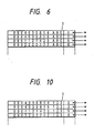
- date and time data at the time of image reading from clocking means 16 is stored together with apparatus identification code of identification code setting means 17 in an empty area of directory 3, as shown in Fig. 6.
- image identification code contains apparatus identification code
- image data can be stored such that they are capable of independent retrieval from each other.
- directory 3 is managed in a manner as shown in Fig. 7.
- directories 113 and 213 are for opto-magnetic disk data storing media 110 and 210 carrying stored data.
- image identification data after copying and synthesis are synthesized and managed on directory 313 for a directory produced for a plurality of data storing media is provided with own image identification codes.
- Fig. 8 is a block diagram showing the construction of a third embodiment of the invention.
- identification code holding medium reading means 28 for reading identification code from identification code holding medium 29 is provided in lieu of identification code setting means 17 in the preceding second embodiment.
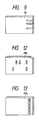
- identification code holding medium 29 may be used a card provided with slits representing identification code, as shown in Fig. 9.
- data and time data at the time of image reading from clocking means 16 is stored together with apparatus identification code of identification code holding medium reading means 28 in an empty area of directory 4, as shown in Fig. 10.
- image identification code contains identification code peculier to identification code holding medium 29, even when image read out at identical time with different image filing apparatus are copied on a common image filing apparatus or image storing medium, both image data can be stored such that they are capable of independent retrieval from each other.
- directory 3 is managed in a manner as shown in Fig. 11.
- directories 123 and 223 are for opto-magnetic disk data storing media 120 and 220 carrying stored data.
- image identification data after copying and synthesis are synthesized and managed on directory 323 for a directory produced for a plurality of data storing media is provided with own image identification codes.
- the identification code holding medium may be of various forms.
- Fig. 12 shows a different example of the medium, which is card 29a provided with a mark representing identification code.
- Fig. 13 shows a further example of the medium, which is a card or IC card with a magnetic zone representing identification code.
- Fig. 14 is a block diagram showing the construction of a fourth embodiment of the invention.
- communication line interface 36 connecting communication line 37 and system bus 30 is provided for storing data received from the outside.
- received image read out by image reading means on transmitter side or retrieval image read out by image reading apparatus 25 of this apparatus is contracted to produce index image data which is stored.
- relative data representing relation between index image data and data for retrieval is also produced and stored.
- index data file 41 storing index image data 1-0 to 1-m and relative data file 42 for producing and storing relative data noted above are provided as a stage preceding directory 3.
- data sequence as shown in Fig. 16 is stored.
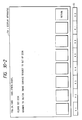
- Fig. 17 illustrates the key array on keyboard 15.
- keys 15-0 to 15-8 are provided around liquid crystal display 23 for displaying index images 23-0 to 23-19 thereon.
- Individual index images 23-0 to 23-19 can be designated one by one by combinations of keys 15-0 to 15-4 arranged horizontally and keys 15-5 to 15-8 arranged vertically.
- the operator designates a retrieval index image registration mode from keyboard 15 and designates the position of display area for index image registration thereon with a combination of keys 15-0 to 15-4 and 15-5 to 15-8. Then an original carrying the index images is set on image reading apparatus 25.
- CPU 11 detects through image reading apparatus interface circuit 24 that the original is set. Consequently, it provides a start signal to image reading apparatus 25 through image reading apparatus interface circuit 24 for reading of index image production image data into an image reading area of RAM 13. When storing received image data, the received image data is stored in the image reading area of RAM 13 before the registration.
- the index image production image data which is read into the image reading area of RAM 13 is ordinary size image data.
- the number of pixels of the read-out image data and those of liquid crystal display 23 do not coincide.
- the original image is contracted for reading by limiting area
- the index image data is made ordinary size image data and contracted when displayed
- ordinary size image data is contracted as index image
- the method in (3) is adopted to produce index image.
- CPU 11 selects bits corresponding to a given contraction factor among the bits corresponding to the pixels of image data on RAM 13 and copies the image in a contracted scale in the index image area of RAM 13. This bit reduction is to produce index image by selecting one pixel for every 5 pixels in case when the contraction factor is 1/5. This is done in both vertical and horizontal directions of the image.
- index image is produced in the index image area of RAM 13.
- CPU 11 displays the index image data in RAM 13 on a designated area of liquid crystal display 23, while also storing this index image data in an index image file area of opto-magnetic disk memory apparatus 21 through opto-magnetic disk memory apparatus interface circuit 20.
- the operator instructs CPU 11 to read in image data to be registered from the keyboard and sets original image on image reading apparatus 25.
- CPU 11 detects, through image reading apparatus interface circuit 24, that the original is set. In consequence, it starts image reading apparatus 25 through image reading apparatus interface circuit 24 for reading image data into RAM 13. In addition, for confirmation of exposing, CPU 11 displays image data in RAM 13 on liquid crystal display 23. Further, CPU 11 stores image data in an empty data file area of opto-magnetic disk memory apparatus 21 through opto-magnetic disk memory apparatus interface circuit 20.
- the operator adds index to image data stored in opto-magnetic disk memory apparatus 21 in the following way.
- Fig. 18 is a flow chart illustrating operation when adding index.
- step S1 When the operator designates addition of index with keyboard 15 (step S1), CPU 11 loads subject image with index to be added thereto in RAM 13 from the data file area of opto-magnetic disk memory apparatus 21 and displays it on liquid crystal display 23 (step S2).
- step S3 the operator selects index image corresponding to the contents displayed on liquid crystal display 23 in terms of a combination of keys 15-0 to 15-4 and 15-5 to 15-8 (step S3).
- CPU 11 sets a designated bit position in bit sequence corresponding to subject image of index addition in relative data area to "1" (step S4).
- step S5 The above sequence of operations is repeated (step S5), whereby relative data consisting of a combination of "0"s and “1"s is produced in the bit sequence corresponding to the called image data among bit sequences 0 to n in the relative data file.
- step S6 When relative data corresponding to image data is produced, the routine goes back to step S2 for index addition to next image data (step S6).
- the above sequence of operations is repeatedly executed for all image data to complete the index addition.
- the relative data is managed by CPU 11 such that data in RAM 13 and data in opto-magnetic disk memory apparatus 21 or floppy disk memory apparatus 19 are of the same contents.
- Fig. 19 is a flow chart illustrating operation of retrieval of data in opto-magnetic disk memory apparatus 21.
- the operator first designates a retrieval mode from keyboard 15 (step S11) and then designates index image related to image for retrieval among a plurality of index images displayed on liquid crystal display 23 in terms of a combination of keys 15-0 to 15-4 and 15-5 to 15-8 (step S12). It is possible to designate a plurality of index images at a time. Further, when the opto-magnetic disk is set, index image is transferred therefrom to RAM 13.
- CPU 11 searches the relative data file for bit pattern of bit position specified by designated index data for each bit sequence (step S13). When a pertaining bit pattern is found, image data corresponding to that bit sequence satisfies a retrieval condition (step S14). Thus, CPU 11 reads out corresponding image data from opto-magnetic disk memory apparatus 21 and loads it in RAM 13 (step S15). If there is no pertaining bit pattern, after searching all the bit sequences, CPU 11 displays a message indicative of absence of pertaining image, thus bringing an end to the process (step S16).
- sequential image display may be executed, or alternatively the number of list of pertaining images may be displayed.
- an original of index image may be produced with a large drawing or character which can be easily drawn by the operator, and index image may be read without paying particular conditions to the reading position, thus permitting operability improvement.
- image data for retrieval is stored prior to the storing of retrieval data, converse storing is also possible.
- stored data is displayed for selecting index image corresponding to the displayed data, it is also possible to let index image to be selected at the time of storing.
- index image may be formed by trimming part of original image.
- this embodiment concerns image data as retrieval data
- switches for designating rows and columns are provided for permitting selection of index image
- a touch panel mounted in liquid crystal display or designation may be effected on the basis of a number input from numeric keys.
- Fig. 20 is a block diagram showing a fifth embodiment of the invention.
- image contraction means 38 is provided between image reading apparatus 25 and image reading apparatus interface circuit 24.
- Image contraction means 38 effects image contraction when index image is read out, and it includes a resister, a counter, and an AND gate and an OR gate.
- relative data file 200A of this embodiment has pointer areas 201, 202, ... corresponding to the respective index images.
- CPU 11 detects that original is set in image reading apparatus 25 by the operator, it renders image contraction means 38 operative and then starts image reading apparatus 25 to supply image data to image contraction means 38.
- Image contraction means 38 contracts input image data with a predetermined contraction factor to produce index image data, which is supplied to image reading apparatus interface circuit 24. The image contraction is effected by removing one pixel for every five pixels in one of every five main scanning lines in case when the contraction factor is 1/5.
- index image is displayed and stored in the manner as described before in connection with the fourth embodiment.
- retrieval data is stored in the manner as in the fourth embodiment.
- CPU 11 sets a pointer of the image to the directory in a pointer area of relative data file 200A corresponding to the designated index image.
- the retrieval is carried out in the manner as in the fourth embodiment.
- any data which absolutely corresponds to the file name of the like of data of selected index image is selected.
- Fig. 22 is a schematic view showing the memory area construction for data retrieval in a sixth embodiment of the invention.
- index data identification data area 6 is provided between index image data file 41 and relative data file 42 shown in Fig. 15.
- this data filing apparatus is the same as that shown in Fig. 1. Meanwhile, this apparatus is provided with the same keyboard as shown in Fig. 17.
- index image is stored in index image file area of opto-magnetic disk memory apparatus 21 in the same procedure as in the fourth embodiment described before in connection with Fig. 15.
- FIG. 23 is a schematic view showing a specific example of index image identification data area 6.
- index data is managed as follows.
- directories 107 and 207 are for opto-magnetic disk data storing media 100a and 200a carrying stored data.
- image identification data after copying and synthesis are synthesized and managed on directory 307 for a directory produced for a plurality of data storing media is provided with own image identification codes.
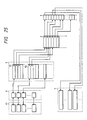
- Fig. 25 is a schematic view showing the memory area construction for data retrieval in a seventh embodiment of the invention.
- relative data file 9 having pointer areas 91, 92, ... corresponding to the respective index data indentification data is provided in lieu of relative data file 41 shown in Fig. 22.
- this data filing apparatus is the same as that shown in Fig. 5.
- this data filing apparatus is provided with the same keyboard as shown in Fig. 17.
- CPU 11 sets a pointer of the image to the directory in a pointer area of relative data file 9 that corresponds to the designated index image.
- Fig. 26 is a schematic view showing a specific example of index image identification data area 6.
- index data is managed as follows.
- directories 117 and 217 are for opto-magnetic disk data storing media 110a and 210a carrying stored data.
- image identification data after copying and synthesis are synthesized and managed on directory 317 for a directory produced for a plurality of data storing media is provided with own image identification codes.
- Fig. 28 is a perspective view showing an embodiment of the invention.
- This embodiment comprises keyboard 52 for providing operation commands to control electronic data filing apparatus 1 and receiving character and numeral data, signal line 52a connecting electronic data filing apparatus 1 and keyboard 52, plate-like display 54 such as an electroluminescence, plasma or fluorescent display tube, key group 5, side plates 56a and 56b provided on original table 7 for transveral displacement relative thereto to restrict original 53 in transversal directions, switch knob 58 for switching between automatic feeding of a plurality of originals 53 and one-by-one manual feeding of originals, tray 59 for supporting originals 53 and discharging tray 50.
- keyboard 52 for providing operation commands to control electronic data filing apparatus 1 and receiving character and numeral data
- signal line 52a connecting electronic data filing apparatus 1 and keyboard 52
- plate-like display 54 such as an electroluminescence, plasma or fluorescent display tube
- key group 5 side plates 56a and 56b provided on original table 7 for transveral displacement relative thereto to restrict original 53 in transversal directions
- switch knob 58 for switching between automatic feeding of a plurality of originals 53 and one-by-one manual feeding
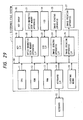
- Fig. 29 is a block diagram showing mainly the inner construction of electronic filing apparatus 1 in this embodiment.
- Electronic filing apparatus 1 includes CPU 11 for controlling entire electronic filing apparatus 1, ROM 12 in which programs for the flow charts shown in Figs. 31 to 34 are stored, RAM 13 used as work memory or the like, keyboard interface 14 for keyboard 52, clocking means 16 for counting date and time, key interface 18 for key group 55, opto-magnetic disk memory apparatus 21 for storing image data or the like on an opto-magnetic disk, opto-magnetic disk memory apparatus interface 20, an LCD as an example of display 54, LCD interface 22, image reading apparatus 25, image reading apparatus interface 24 and printing apparatus interface 26.
- Electronic filing apparatus 1 is connected to keyboard 52 and image printing apparatus 27.
- Figs. 30-1 to 30-5 are views showing examples of display on display 54 in different states of the embodiment.
- a display as shown in Fig. 30-1 takes place.
- a display as shown in Fig. 30-2 takes place.
- initial image display is caused, as shown in Fig. 30-3.
- key K8 in key group 55 is depressed in the state shown in Fig. 30-1, and the date is corrected by operating keyboard 2.
- stamp is meant a retrieval image representing retrieval data, and a plurality of stamps are provided as retrieval data to one image.
- a retrieval mode display as shown in Fig. 30-4 is produced.
- a retrieval list as shown in Fig. 30-5 is displayed on display 54.
- Fig. 31 is a flow chart illustrating an operation of registering original 53 in electronic data filing apparatus 1.
- originals 53 are exposed one by one for taking their pictures by image reading apparatus 25 (step S1), and resultant images obtained are registered on disk (step S2).
- machine number of electronic filing apparatus 1 apparatus identification code
- date and time of exposure and file index including stamps
- image, machine number, data and time and index are registered substantially simultaneously.
- Fig. 32 is a flow chart illustrating the operation of selecting retrieval data in this embodiment.
- retrieval mode key K2 is depressed to provide retrieval mode display as shown in Fig. 30-4 (step S11), for confirming usage of stamp, keyword, key number or date ID as retrieval data.
- Stamp usage selection of retrieval data (S12) is executed in an operation shown by the flow chart of Fig. 33 (step S13).
- step S14 and S16 a given keyword and a given key number are supplied from keyboard 52 to keyword and key number entry positions in a right upper portion of the retrieval mode display shown in Fig. 30-4 for retrieval data selection (steps S15 and S17).
- step S18 the range of date ID is entered in a date ID position in a right portion of the retrieval mode display from keyboard 52 (step S19).
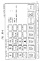
- Fig. 30-4 shows an example of retrieval mode display.
- stamps K(1,2) to K(4, 5) are displayed in a four-row five-column matrix as an example of stamp display.
- left hand figures represent rows, and right hand figures columns.
- Stamp selection keys K1 to K5 are each provided for each of the stamp columns.
- Keys K5, K7 and K8 are respectively a decision key, a retrieval execution key and a return key.
- a tentative selection display i.e., a display indicative of the fact that a stamp is tentatively selected (which is turning-down of stanp by one-third turn) is provided with step-by-step shift of stamp belonging to the depressed stanp selection key. That is, the tentative selection display is shifted by one row after another in the stamp column belonging to the depressed stamp selection key.
- decision key K6 is depressed, the tentatively selected stamp is regularly selected, whereupon the tentative selection display is changed to a regular selection display (i.e., which is complete turning of stamp).
- Fig. 33 is a flow chart showing an operation of retrieval data selection with use of stamp in this embodiment.
- step S13a In a state, in which the retrieval mode display is provided and variables m, n, ... are reset to zero (step S13a), with depression of stamp selection key K1, for instance (step S20) variable m is incremented by one, and only stamp K(m, 1) is turned down by one-third turn for tentative selection display (step S22). If decision key K6 is depressed at this time (step S13b), the stamp of tentative selection display is completely turned for regular selection display (step S13c), and image corresponding to the stamp in regular selection display is registered in retrieval list (step S13d). Then. the next stamp is selected. For cancelling a stamp in tentative selection display, selection key K1 is depressed with stamp K(4, 1) in tentative selection display.
- selection key K1 is depressed several times. When a regularly selected stamp is selected again, it is turned up by two-third turn to make lower one-third white. By depressing decision key K6 in this state, the regular selection of this stamp is cancelled.
- step S30 When stamp selection key K2 is depressed (step S30), variable n is incremented by one (step S31), and only stamp K(n, 2) is turned down by one-third turn for tentative selection display (step S32). If decision key K6 has been depressed at this time (step S13b), the tentatively selected stamp is changed to regular selection display in the manner as described above, and image corresponding to this regularly selected stamp is registered in retrieval list. Then, the next stamp is selected, and if decision key K6 has not been depressed, the routine returns to step S20.
- Variables m and n represent rows in the stamp matrix shown in Fig. 30-4.
- Variables p, q and r represent rows of matrix represented by stamp selection keys K3 to K5.
- stamp selection keys K3 to K5 have been depressed is also executed (steps S33 to S35). If these keys have been depressed, variables p, q and r representing respective rows are each incremented by one, and tentative selection display of stamp belonging to a stamp selection key in question is shifted down by one row. If stamp selection is not completed (step S23), the routine returns to step S13b as noted above. If decision key K6 is depressed, change to regular selection display is effected in the manner as described above.
- stamp selection can be effected by providing stamp selection key only for one row, and this means that the number of stamp selection keys can be reduced, while also facilitating the operation of stamp selection.
- stamp selection key K1 it is possible to set a combination condition for stamp selection with an OR condition for stamp rows of the matrix and with an AND condition for stamp columns of the matrix.
- This arrangement permits selection of practical data combinations.
- stamp selection key K1 setting manufactures for stamps belonging on stamp selection key K2 and setting areas or regions for stamps belonging to stamp selection key K3, it it possible to combine images of areas for each order slit and also each manufacture.
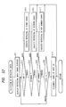
- Fig. 34 is a flow chart illustrating the date ID range designation operation in this embodiment.
- the display on display 54 shown in Fig. 30-4 has a date ID entry position in a right portion.
- a given date ID i.e., date and time
- step S41 If date ID designation is on the left hand column (step S41), date IR designation is on the right hand column (step S42) and decision key K6 is depressed at this time (step S43), image corresponding to the date ID in a range specified by the left and right hand columns of date ID is registered in retrieval list (step S44). If decision key K6 is depressed in the absence of any designation in the right hand column although there is designation in the left hand column (step S45), images corresponding to date IDs subsequent to the date ID specified by the left hand column are registered in the retrieval list (step S46). Further, if decision key is depressed (step S48) in the presence of designation in the right hand column (step S47) although there is no designation in the left hand column, images corresponding to date IDs before the date ID specified by the right hand column (step S49).
- Fig. 30-5 shows an example of retrieval list with date IDs range designated and decided in the above way.
- the date and time are made date ID, but it is possible to make some of the date and time such as date or time to be date ID. Further, it is possible to permit the designation of the range of date ID and designation of retrieval data with use of stamp to be executed in advance and let these designations be used in combination for retrieval. Further, besides the designation of date ID the designation of keyword, key number, etc. may be used in combination with the designation of retrieval data with use of stamp. Further, it is possible to arrange such that other keys than decision key (steps S43, S45 and S48), for instance the return key on keyboard 2, may be depressed to the same end.
- stamp selection keys K1 to K5 are arranged in a row on screen 54, it is also possible to adopt key arrangement in a column.
Abstract
Description
- This invention relates to data retrieval in electronic filing apparatus.
- In prior art memory apparatus having data retrieval function, data retrieval is carried out using retrieval data such as data file name, keyword corresponding to stored data and code number provided according to a predetermined rule. The retrieval data is produced according to data designated by a keyboard or the like.
- When data retrieval in the prior art apparatus is carried out using file name, one file can not be given many characters, and it is impossible to permit various types of retrieval.
- Where keyword is used for retrieval, a great deal of man-hour is required for the selection of keyword. In addition, it is difficult to designate an adequate keyword at the time of retrieval because there are many different words representing similar concepts.
- Where code number is used for retrieval, with increase of memory items it becomes difficult to store code numbers corresponding to contends of retrieval. In practice, a code number has to be selected by using a conversion table at all time.
- In either case noted above, it is necessary to input file name, keyword and code number by keying operation when storing data and also when executing retrieval. This operation requires skill and time, and it is difficult to increase the operational efficiency.
- Further, with the prior art apparatus, if it is desired to retrieve images obtained from October toward December of the last year or images obtained since 10 to 20 days ago, keywords or key numbers corresponding to the time when the images are obtained are searched for, and image retrieval is carried out on the basis of the keywords or key numbers that are found.
- Therefore, when only the date and time of exposing are known, long time is required for the preparations for the image retrieval.
- An object of the invention is to provide an electronic filing apparatus, which can overcome the drawbacks discussed above.
- Another object of the invention is to provide an electronic filing apparatus, which permits ready and speedy data retrieval operation.
- A further object of the invention is to provide an electronic filing apparatus, which can display retrieval data and permits ready selection thereof.
- A still further object of the invention is to provide an electronic filing apparatus, which can simplify retrieval operation when the range of date and time of image registration is known.
- The above and other objects of the invention will become more apparent from the following description with reference to the accompanying drawings.
-
- Fig. 1 is a block diagram showing the construction of a first embodiment of the data filing apparatus according to the invention;
- Fig. 2 is a schematic view showing memory area construction for data retrieval in the same embodiment;
- Fig. 3 is a schematic view showing specific contents of a directory in the same embodiment;
- Fig. 4 is a schematic view showing a directory management system when copying data on more than one data storing media in the same embodiment;
- Fig. 5 is a block diagram showing the construction of a second embodiment of the data filing apparatus according to the invention;
- Fig. 6 is a schematic view showing specific contents of a directory in the same embodiment;
- Fig. 7 is a schematic view showing a directory management system when copying data on more than one data storing media in the same embodiment;
- Fig. 8 is a block diagram showing the construction of a third embodiment of the data filing apparatus according to the invention;
- Fig. 9 is a plan view showing an indentification code holding medium used in the same embodiment;
- Fig. 10 is a schematic view showing specific contents of a directory in the same embodiment;
- Fig. 11 is a schematic view showing a directory management system when copying data on more than one data storing medium in the same embodiment;
- Fig. 12 is a plan view showing a different example of identification code holding medium;
- Fig. 13 is a plan view showing a further example of identification code holding medium;
- Fig. 14 is a block diagram showing the construction of a fourth embodiment of the data filing apparatus according to the invention;
- Fig. 15 is a schematic view showing memory area construction for data retrieval in the same embodiment;
- Fig. 16 is a schematic view showing data arrangement on disk in the same embodiment;
- Fig. 17 is a front view showing a key arrangement of a keyboard in the same embodiment;
- Fig. 18 is a flow chart illustrating an operation of index addition in the same embodiment;
- Fig. 19 is a flow chart illustrating an operation of retrieval of images in an opto-magnetic disk memory apparatus in the same embodiment;
- Fig. 20 is a block diagram showing a fifth embodiment of the data filing apparatus according to the invention;
- Fig. 21 is a schematic view showing memory area construction for data retrieval in the same embodiment;
- Fig. 22 is a schematic view showing memory area construction for data retrieval in a sixth embodiment of the data filing apparatus according to the invention;
- Fig. 23 is a schematic view showing specific contents in an index image identification data area in the same embodiment;
- Fig. 24 is a schematic view showing a directory management system when copying data on more than one data storing medium in the same embodiment;
- Fig. 25 is a schematic view showing memory area construction for data retrieval in a seventh embodiment of the data filing apparatus according to the invention;
- Fig. 26 is a schematic view showing specific contents of an index image identification data area in the same embodiment;
- Fig. 27 is a schematic view showing a directory management system when copying data on more than one data storing medium in the same embodiment;
- Fig. 28 is a perspective view showing an electronic data filing apparatus, to which the invention is applicable;
- Fig. 29 is a block diagram showing the construction of an electronic data filing apparatus of the same embodiment;
- Figs. 30-1 to 30-5 are views showing examples of display on a display in the same embodiment;
- Fig. 31 is a flow chart illustrating a basic operation of registration in the same embodiment;
- Fig. 32 is a flow chart illustrating an operation of retrieval data selection in the same embodiment;
- Fig. 33 is a flow chart illustrating an operation of retrieval data selection with use of stamp in the same embodiment; and
- Fig. 34 is a flow chart illustrating an operation of date ID range specification in the same embodiment.
- Fig. 1 is a block diagram showing the construction of a first embodiment of the invention.
- This data filing apparatus comprises
central processor 10,keyboard 15, opto-magneticdisk memory apparatus 21,liquid crystal display 23,image reading apparatus 25 andimage printing apparatus 27. -
Central processor 10 includesCPU 11 as microprocessor,ROM 12 in which operation programs ofCPU 11 are stored, andRAM 13 providing a word area ofCPU 11 and a load area for various data and programs. -
Central processor 10 further includeskeyboard interface circuit 14 connectingkeyboard 15 andsystem bus 30, floppy diskdevice interface circuit 19 connectingfloppy disk device 19 andsystem bus 30, opto-magnetic disk memoryapparatus interface circuit 20 connecting opto-magnetic disk apparatus 21 andsystem bus 30, liquid crystaldisplay interface circuit 22 connectingliquid crystal display 23 andsystem bus 30, image readingapparatus interface circuit 24 connectingimage reading apparatus 25 andsystem bus 30, and image printingapparatus interface circuit 26 connectingimage printing apparatus 27 andsystem bus 26. - Clocking means 16 for counting data and time is further connected to
system bus 30. - Fig. 2 is a schematic view showing a memory area configuration in this embodiment of data filing apparatus.
- In this data filing apparatus, the retrieval of image
data file group 5 is executed withdirectory 3 with retrieval data stored therein and FAT (file allocation table 4) for managing data recording addresses in recording medium. In this embodiment, when storing image data the corresponding date and time are input from clockingmeans 16, the date and time data being written in an empty area ofdirectory 3, as shown in Fig. 3, and used as image identification data. - A summary of the operation of this data filing apparatus will now be described.
- When the operator closes a power source switch (not shown),
CPU 11 executes checking of the RAM and initializes internal parameters prescribed inROM 12, executes initialization of the individual interface circuits and clears the liquid crystal display according to a program prescribed inROM 12 to be ready for operation of the keyboard by the operator. - Subsequently, the operator instructs
CPU 11 to read in image data for registration from the keyboard and sets original image onimage reading apparatus 25. -
CPU 11 detects, with a sensor provided in an original setting section of the image reading apparatus and through image readingapparatus interface circuit 24, that the original is set. In consequence, it provides a start signal to image readingapparatus 25 through image readingapparatus interface circuit 24 for reading image data intoRAM 13. Further, for giving confirmation of exposing to the operator,CPU 11 displays image data inRAM 13 onliquid crystal display 23 through liquid crystals displayinterface circuit 23. - Then,
CPU 11 receives image reading date and time data from clocking means 16 and stores as image discrimination code in an empty area ofdirectory 3 in opto-magneticdisk memory apparatus 21 through opto-magnetic disk memoryapparatus interface circuit 20. Further, it stores image data in an empty area of data file in opto-magneticdisk memory apparatus 21. - The relation between image identification codes in
directory 3 and image data is managed by providingdirectory 3 with pointers representing FAT numbers corresponding to image data memory areas. - Fig. 4 is a schematic view showing a system for managing
directory 3 when copying data of data storing media. - Referring to Fig. 4,
directories data storing media - When copying the data on these two media on a common opto-magnetic disk medium, image identification data after copying and synthesis are synthesized and managed on
directory 303 for a directory produced for a plurality of data storing media is provided with own image identification codes. - In this embodiment, opto-magnetic disks are used as image storing medium. However, this is by no means limitative, and it is possible to use magnetic disks, optical disks, IC cards, laser cards, etc. as well. This also applies to the following embodiments as well.
- Fig. 5 is a block diagram showing the construction of a second embodiment of the invention.
- In this embodiment of image filing apparatus, identification code setting means 17 is provided in addition to identification codes in the clocking means of the preceding embodiment. Identification code setting means 17 consists of dip switches or batter backed-up RAM. Given code data is set as apparatus identification code by the operator by switch operation or keying operation prior to the image reading operation.
- In this embodiment, like the above embodiment, date and time data at the time of image reading from clocking means 16 is stored together with apparatus identification code of identification code setting means 17 in an empty area of
directory 3, as shown in Fig. 6. - Since in this embodiment image identification code contains apparatus identification code, even when image read out at identical time with different image filling apparatus are copied on a common image filing apparatus or image storing medium, both image data can be stored such that they are capable of independent retrieval from each other. In this case,
directory 3 is managed in a manner as shown in Fig. 7. - Referring to Fig. 7,
directories data storing media - When copying the data on these two media on a common opto-magnetic disk medium, image identification data after copying and synthesis are synthesized and managed on
directory 313 for a directory produced for a plurality of data storing media is provided with own image identification codes. - The other construction and operation are substantially the same as those of the previous embodiment.
- Fig. 8 is a block diagram showing the construction of a third embodiment of the invention.
- In this embodiment of image filing apparatus, identification code holding medium reading means 28 for reading identification code from identification
code holding medium 29 is provided in lieu of identification code setting means 17 in the preceding second embodiment. As identificationcode holding medium 29 may be used a card provided with slits representing identification code, as shown in Fig. 9. - In this embodiment, like the preceding embodiment, data and time data at the time of image reading from clocking means 16 is stored together with apparatus identification code of identification code holding medium reading means 28 in an empty area of
directory 4, as shown in Fig. 10. - Since in this embodiment image identification code contains identification code peculier to identification
code holding medium 29, even when image read out at identical time with different image filing apparatus are copied on a common image filing apparatus or image storing medium, both image data can be stored such that they are capable of independent retrieval from each other. In this case,directory 3 is managed in a manner as shown in Fig. 11. - Referring to Fig. 11,
directories data storing media - When copying the data on these two media on a common opto-magnetic disk medium, image identification data after copying and synthesis are synthesized and managed on
directory 323 for a directory produced for a plurality of data storing media is provided with own image identification codes. - The other construction and operation are substantially the same as those of the previous embodiment.
- The identification code holding medium may be of various forms. Fig. 12 shows a different example of the medium, which is
card 29a provided with a mark representing identification code. Fig. 13 shows a further example of the medium, which is a card or IC card with a magnetic zone representing identification code. - Fig. 14 is a block diagram showing the construction of a fourth embodiment of the invention.
- In this data filing apparatus,
communication line interface 36 connectingcommunication line 37 andsystem bus 30 is provided for storing data received from the outside. - In this embodiment, received image read out by image reading means on transmitter side or retrieval image read out by
image reading apparatus 25 of this apparatus is contracted to produce index image data which is stored. In addition, relative data representing relation between index image data and data for retrieval is also produced and stored. By selecting index image data, data retrieval is executed according to relative data. - In this embodiment, as shown in Fig. 15, index data file 41 storing index image data 1-0 to 1-m and relative data file 42 for producing and storing relative data noted above are provided as a
stage preceding directory 3. On actual disk, data sequence as shown in Fig. 16 is stored. - Fig. 17 illustrates the key array on
keyboard 15. - In this embodiment, keys 15-0 to 15-8 are provided around
liquid crystal display 23 for displaying index images 23-0 to 23-19 thereon. Individual index images 23-0 to 23-19 can be designated one by one by combinations of keys 15-0 to 15-4 arranged horizontally and keys 15-5 to 15-8 arranged vertically. - Now, a summary of the operation of this embodiment will be described.
- After closure of the power source, the operator designates a retrieval index image registration mode from
keyboard 15 and designates the position of display area for index image registration thereon with a combination of keys 15-0 to 15-4 and 15-5 to 15-8. Then an original carrying the index images is set onimage reading apparatus 25. -
CPU 11 detects through image readingapparatus interface circuit 24 that the original is set. Consequently, it provides a start signal to image readingapparatus 25 through image readingapparatus interface circuit 24 for reading of index image production image data into an image reading area ofRAM 13. When storing received image data, the received image data is stored in the image reading area ofRAM 13 before the registration. - The index image production image data which is read into the image reading area of
RAM 13 is ordinary size image data. On the other hand, it is necessary to display a plurality of (practically 8 to 30) index images at a time onliquid crystal display 23. The number of pixels of the read-out image data and those ofliquid crystal display 23 do not coincide. - To overcome this three methods are conceivable; (1) the original image is contracted for reading by limiting area, (2) the index image data is made ordinary size image data and contracted when displayed, and (3) ordinary size image data is contracted as index image.
- In the method in (1), a small size original has to be produced, which is difficult. In addition, alignment at the time of reading is difficult. In the method in (2) the index image can be read quickly. However, its data amount is large, thus increasing the occupied area of the data filing apparatus. Besides, time for contracting process is necessary when displaying the index image.
- Accordingly, in this embodiment the method in (3) is adopted to produce index image.
- More specifically, according to a program stored in
ROM 12CPU 11 selects bits corresponding to a given contraction factor among the bits corresponding to the pixels of image data onRAM 13 and copies the image in a contracted scale in the index image area ofRAM 13. This bit reduction is to produce index image by selecting one pixel for every 5 pixels in case when the contraction factor is 1/5. This is done in both vertical and horizontal directions of the image. - In the above way, index image is produced in the index image area of
RAM 13. - Subsequently,
CPU 11 displays the index image data inRAM 13 on a designated area ofliquid crystal display 23, while also storing this index image data in an index image file area of opto-magneticdisk memory apparatus 21 through opto-magnetic disk memoryapparatus interface circuit 20. - In this way, desired index images are registered one after another.
- Subsequently, the operator instructs
CPU 11 to read in image data to be registered from the keyboard and sets original image onimage reading apparatus 25. -
CPU 11 detects, through image readingapparatus interface circuit 24, that the original is set. In consequence, it startsimage reading apparatus 25 through image readingapparatus interface circuit 24 for reading image data intoRAM 13. In addition, for confirmation of exposing,CPU 11 displays image data inRAM 13 onliquid crystal display 23. Further,CPU 11 stores image data in an empty data file area of opto-magneticdisk memory apparatus 21 through opto-magnetic disk memoryapparatus interface circuit 20. - Subsequently, the operator adds index to image data stored in opto-magnetic
disk memory apparatus 21 in the following way. - Fig. 18 is a flow chart illustrating operation when adding index.
- When the operator designates addition of index with keyboard 15 (step S1),
CPU 11 loads subject image with index to be added thereto inRAM 13 from the data file area of opto-magneticdisk memory apparatus 21 and displays it on liquid crystal display 23 (step S2). - Then, the operator selects index image corresponding to the contents displayed on
liquid crystal display 23 in terms of a combination of keys 15-0 to 15-4 and 15-5 to 15-8 (step S3). -
CPU 11 then sets a designated bit position in bit sequence corresponding to subject image of index addition in relative data area to "1" (step S4). - The above sequence of operations is repeated (step S5), whereby relative data consisting of a combination of "0"s and "1"s is produced in the bit sequence corresponding to the called image data among
bit sequences 0 to n in the relative data file. - When relative data corresponding to image data is produced, the routine goes back to step S2 for index addition to next image data (step S6). The above sequence of operations is repeatedly executed for all image data to complete the index addition.
- The relative data is managed by
CPU 11 such that data inRAM 13 and data in opto-magneticdisk memory apparatus 21 or floppydisk memory apparatus 19 are of the same contents. - Fig. 19 is a flow chart illustrating operation of retrieval of data in opto-magnetic
disk memory apparatus 21. - In the retrieval of data that has been subjected to index addition as described above, the operator first designates a retrieval mode from keyboard 15 (step S11) and then designates index image related to image for retrieval among a plurality of index images displayed on
liquid crystal display 23 in terms of a combination of keys 15-0 to 15-4 and 15-5 to 15-8 (step S12). It is possible to designate a plurality of index images at a time. Further, when the opto-magnetic disk is set, index image is transferred therefrom toRAM 13. - Then,
CPU 11 searches the relative data file for bit pattern of bit position specified by designated index data for each bit sequence (step S13). When a pertaining bit pattern is found, image data corresponding to that bit sequence satisfies a retrieval condition (step S14). Thus,CPU 11 reads out corresponding image data from opto-magneticdisk memory apparatus 21 and loads it in RAM 13 (step S15). If there is no pertaining bit pattern, after searching all the bit sequences,CPU 11 displays a message indicative of absence of pertaining image, thus bringing an end to the process (step S16). - If there are a plurality of image data satisfying the retrieval condition, there is no problem. In this case, sequential image display may be executed, or alternatively the number of list of pertaining images may be displayed.
- As has been shown, with this embodiment at the time of registration of index image an original of index image may be produced with a large drawing or character which can be easily drawn by the operator, and index image may be read without paying particular conditions to the reading position, thus permitting operability improvement.
- Further, while in this embodiment image data for retrieval is stored prior to the storing of retrieval data, converse storing is also possible.
- Further, while in this embodiment stored data is displayed for selecting index image corresponding to the displayed data, it is also possible to let index image to be selected at the time of storing.
- Further, while in this embodiment image contraction is executed at the time of registration of index image, this is not necessary; for instance index image may be formed by trimming part of original image.
- Further, while this embodiment concerns image data as retrieval data, this is by no means limitative, and the invention covers various kinds of data and registration routes thereof such as code data from communication lines, compressed image data and code data on floppy disks.
- Further, the data arrangement on the data storing medium in this embodiment is only a theoretical model for the sake of explanation and is by no means limitative.
- In addition, there is no need of storing image data, relative data and retrieval data on the same data storing medium, and these data may be stored distributedly on a plurality of media as well.
- Further, while in this embodiment switches for designating rows and columns are provided for permitting selection of index image, it is also possible to use a touch panel mounted in liquid crystal display, or designation may be effected on the basis of a number input from numeric keys.
- Fig. 20 is a block diagram showing a fifth embodiment of the invention.
- In this embodiment, image contraction means 38 is provided between
image reading apparatus 25 and image readingapparatus interface circuit 24. Image contraction means 38 effects image contraction when index image is read out, and it includes a resister, a counter, and an AND gate and an OR gate. - Further, relative data file 200A of this embodiment, as shown in Fig. 21, has
pointer areas - In the operation of index image registration in this embodiment, when
CPU 11 detects that original is set inimage reading apparatus 25 by the operator, it renders image contraction means 38 operative and then startsimage reading apparatus 25 to supply image data to image contraction means 38. Image contraction means 38 contracts input image data with a predetermined contraction factor to produce index image data, which is supplied to image readingapparatus interface circuit 24. The image contraction is effected by removing one pixel for every five pixels in one of every five main scanning lines in case when the contraction factor is 1/5. - Subsequently, index image is displayed and stored in the manner as described before in connection with the fourth embodiment.
- Further, retrieval data is stored in the manner as in the fourth embodiment. In the index addition operation of this embodiment, when index image of retrieval image is designated by a combination of keys 15-0 to 15-4 and 15-5 to 15-8,
CPU 11 sets a pointer of the image to the directory in a pointer area of relative data file 200A corresponding to the designated index image. - The retrieval is carried out in the manner as in the fourth embodiment.
- In this embodiment, any data which absolutely corresponds to the file name of the like of data of selected index image.
- Fig. 22 is a schematic view showing the memory area construction for data retrieval in a sixth embodiment of the invention.
- In this data filing apparatus, index data
identification data area 6 is provided between index image data file 41 and relative data file 42 shown in Fig. 15. For the rest, this data filing apparatus is the same as that shown in Fig. 1. Meanwhile, this apparatus is provided with the same keyboard as shown in Fig. 17. - When registering index image with this data filing apparatus, index image is stored in index image file area of opto-magnetic
disk memory apparatus 21 in the same procedure as in the fourth embodiment described before in connection with Fig. 15. - When reading this index data,
CPU 11 receives data and time data of present data and time from clocking means 16, and it stores this data as index image identification data in an address of index imageidentification data area 6 of opto-magneticdisk memory apparatus 21 that corresponds to the index image stored this time. Fig. 23 is a schematic view showing a specific example of index imageidentification data area 6. - The storing of retrieval data, addition of index and retrieval are performed in the same manner as in the fourth embodiment.
- In the copying of data on more than one data storing medium, index data is managed as follows.
- Referring to Fig. 24,
directories data storing media - When copying the data on these two media on a common opto-magnetic disk medium, image identification data after copying and synthesis are synthesized and managed on
directory 307 for a directory produced for a plurality of data storing media is provided with own image identification codes. - Fig. 25 is a schematic view showing the memory area construction for data retrieval in a seventh embodiment of the invention.
- In this data filing apparatus, relative data file 9 having
pointer areas - In this data filing apparatus, registration of index data, storing of retrieval data and retrieval are performed in the same manner as in the sixth embodiment.
- Further, in the index addition operation of this embodiment, when index image of retrieval image is designated by keys 15-0 to 15-8,
CPU 11 sets a pointer of the image to the directory in a pointer area of relative data file 9 that corresponds to the designated index image. - Fig. 26 is a schematic view showing a specific example of index image
identification data area 6. - In the copying of data on more than one data storing medium, index data is managed as follows.
- Referring to Fig. 27,
directories data storing media 110a and 210a carrying stored data. - When copying the data on these two media on a common opto-magnetic disk medium, image identification data after copying and synthesis are synthesized and managed on
directory 317 for a directory produced for a plurality of data storing media is provided with own image identification codes. - As has been shown, in the above fourth and following embodiments it is possible to obtain designation of a character of retrieval data based on image, and thus retrieval operation can be executed under the sense of the operator. In addition, the operator can easily register index data, thus facilitating the management of the retrieval apparatus and permitting a retrieval system based on the operators creative sense to be readily built. Further, it is possible to reduce memory for storing the relation between index data and retrieval data, thereby greatly improving the retrieval speed.
- Now, the operation at the time of retrieval will be described by using display screen.
- Fig. 28 is a perspective view showing an embodiment of the invention.
- This embodiment comprises
keyboard 52 for providing operation commands to control electronicdata filing apparatus 1 and receiving character and numeral data,signal line 52a connecting electronicdata filing apparatus 1 andkeyboard 52, plate-like display 54 such as an electroluminescence, plasma or fluorescent display tube,key group 5,side plates switch knob 58 for switching between automatic feeding of a plurality oforiginals 53 and one-by-one manual feeding of originals, tray 59 for supportingoriginals 53 and dischargingtray 50. - Fig. 29 is a block diagram showing mainly the inner construction of
electronic filing apparatus 1 in this embodiment. -
Electronic filing apparatus 1 includesCPU 11 for controlling entireelectronic filing apparatus 1,ROM 12 in which programs for the flow charts shown in Figs. 31 to 34 are stored,RAM 13 used as work memory or the like,keyboard interface 14 forkeyboard 52, clocking means 16 for counting date and time,key interface 18 forkey group 55, opto-magneticdisk memory apparatus 21 for storing image data or the like on an opto-magnetic disk, opto-magnetic diskmemory apparatus interface 20, an LCD as an example ofdisplay 54,LCD interface 22,image reading apparatus 25, image readingapparatus interface 24 andprinting apparatus interface 26.Electronic filing apparatus 1 is connected tokeyboard 52 andimage printing apparatus 27. - Now the operation of this embodiment will be described.
- Figs. 30-1 to 30-5 are views showing examples of display on
display 54 in different states of the embodiment. - When the power source of
electronic filing apparatus 1 is closed, a display as shown in Fig. 30-1 takes place. When the present date is confirmed (i.e., when key K1 inkey group 55 is depressed), a display as shown in Fig. 30-2 takes place. When disk is set in this state, initial image display is caused, as shown in Fig. 30-3. For correcting the date, key K8 inkey group 55 is depressed in the state shown in Fig. 30-1, and the date is corrected by operatingkeyboard 2. - It is assumed that the present date and time is displayed in the initial display in an upper portion thereof and stamps K(1, 1) to K(4, 5) are already displayed. In this embodiment, by the term "stamp" is meant a retrieval image representing retrieval data, and a plurality of stamps are provided as retrieval data to one image.
- Subsequently, by depressing key K2 corresponding to a retrieval mode, a retrieval mode display as shown in Fig. 30-4 is produced. Then by executing stamp selection in a manner to be described later, a retrieval list as shown in Fig. 30-5 is displayed on
display 54. - Fig. 31 is a flow chart illustrating an operation of registering original 53 in electronic
data filing apparatus 1. As is shown,originals 53 are exposed one by one for taking their pictures by image reading apparatus 25 (step S1), and resultant images obtained are registered on disk (step S2). Then, machine number of electronic filing apparatus 1 (apparatus identification code), date and time of exposure and file index (including stamps) are registered (steps S3 to S5). Actually, image, machine number, data and time and index are registered substantially simultaneously. - Now, the operation of selecting retrieval data will be described.
- Fig. 32 is a flow chart illustrating the operation of selecting retrieval data in this embodiment.
- First, in the state of initial display shown in Fig. 30-1, retrieval mode key K2 is depressed to provide retrieval mode display as shown in Fig. 30-4 (step S11), for confirming usage of stamp, keyword, key number or date ID as retrieval data.
- Stamp usage selection of retrieval data (S12) is executed in an operation shown by the flow chart of Fig. 33 (step S13). In case of using keyword and key number (steps S14 and S16), a given keyword and a given key number are supplied from
keyboard 52 to keyword and key number entry positions in a right upper portion of the retrieval mode display shown in Fig. 30-4 for retrieval data selection (steps S15 and S17). When using date ID for retrieval data selection (step S18), the range of date ID is entered in a date ID position in a right portion of the retrieval mode display from keyboard 52 (step S19). - Now, an operation of retrieval data selection with use of stamp will be described.
- Fig. 30-4 shows an example of retrieval mode display. In this retrieval mode display, stamps K(1,2) to K(4, 5) are displayed in a four-row five-column matrix as an example of stamp display. In parentheses, left hand figures represent rows, and right hand figures columns. Stamp selection keys K1 to K5 are each provided for each of the stamp columns. Keys K5, K7 and K8 are respectively a decision key, a retrieval execution key and a return key.
- Every time one of stamp selection keys K1 to K5 is depressed once, a tentative selection display, i.e., a display indicative of the fact that a stamp is tentatively selected (which is turning-down of stanp by one-third turn) is provided with step-by-step shift of stamp belonging to the depressed stanp selection key. That is, the tentative selection display is shifted by one row after another in the stamp column belonging to the depressed stamp selection key. When decision key K6 is depressed, the tentatively selected stamp is regularly selected, whereupon the tentative selection display is changed to a regular selection display (i.e., which is complete turning of stamp).
- Fig. 33 is a flow chart showing an operation of retrieval data selection with use of stamp in this embodiment.
- In a state, in which the retrieval mode display is provided and variables m, n, ... are reset to zero (step S13a), with depression of stamp selection key K1, for instance (step S20) variable m is incremented by one, and only stamp K(m, 1) is turned down by one-third turn for tentative selection display (step S22). If decision key K6 is depressed at this time (step S13b), the stamp of tentative selection display is completely turned for regular selection display (step S13c), and image corresponding to the stamp in regular selection display is registered in retrieval list (step S13d). Then. the next stamp is selected. For cancelling a stamp in tentative selection display, selection key K1 is depressed with stamp K(4, 1) in tentative selection display. For cancelling stamp in regular selection display, selection key K1 is depressed several times. When a regularly selected stamp is selected again, it is turned up by two-third turn to make lower one-third white. By depressing decision key K6 in this state, the regular selection of this stamp is cancelled.
- When stamp selection key K2 is depressed (step S30), variable n is incremented by one (step S31), and only stamp K(n, 2) is turned down by one-third turn for tentative selection display (step S32). If decision key K6 has been depressed at this time (step S13b), the tentatively selected stamp is changed to regular selection display in the manner as described above, and image corresponding to this regularly selected stamp is registered in retrieval list. Then, the next stamp is selected, and if decision key K6 has not been depressed, the routine returns to step S20.
- Variables m and n represent rows in the stamp matrix shown in Fig. 30-4. Variables p, q and r represent rows of matrix represented by stamp selection keys K3 to K5.
- Check as to whether stamp selection keys K3 to K5 have been depressed is also executed (steps S33 to S35). If these keys have been depressed, variables p, q and r representing respective rows are each incremented by one, and tentative selection display of stamp belonging to a stamp selection key in question is shifted down by one row. If stamp selection is not completed (step S23), the routine returns to step S13b as noted above. If decision key K6 is depressed, change to regular selection display is effected in the manner as described above.
- In the above way the stamp selection can be effected by providing stamp selection key only for one row, and this means that the number of stamp selection keys can be reduced, while also facilitating the operation of stamp selection.
- It is possible to set a combination condition for stamp selection with an OR condition for stamp rows of the matrix and with an AND condition for stamp columns of the matrix. This arrangement permits selection of practical data combinations. As an example, by setting order slits stamps belonging to stamp selection key K1, setting manufactures for stamps belonging on stamp selection key K2 and setting areas or regions for stamps belonging to stamp selection key K3, it it possible to combine images of areas for each order slit and also each manufacture.
- Now, an operation of designating the range of date ID when selecting image data will be described.
- Fig. 34 is a flow chart illustrating the date ID range designation operation in this embodiment. The display on
display 54 shown in Fig. 30-4 has a date ID entry position in a right portion. A given date ID (i.e., date and time) is entered in left and right hand columns of this display zone fromkeyboard 2. - If date ID designation is on the left hand column (step S41), date IR designation is on the right hand column (step S42) and decision key K6 is depressed at this time (step S43), image corresponding to the date ID in a range specified by the left and right hand columns of date ID is registered in retrieval list (step S44). If decision key K6 is depressed in the absence of any designation in the right hand column although there is designation in the left hand column (step S45), images corresponding to date IDs subsequent to the date ID specified by the left hand column are registered in the retrieval list (step S46). Further, if decision key is depressed (step S48) in the presence of designation in the right hand column (step S47) although there is no designation in the left hand column, images corresponding to date IDs before the date ID specified by the right hand column (step S49).
- Fig. 30-5 shows an example of retrieval list with date IDs range designated and decided in the above way.
- By permitting designation of retrieval data with the date ID designation in the above way, the freedom of retrieval data designation is increased to permit readier retrieval data selection.
- In the above embodiment the date and time are made date ID, but it is possible to make some of the date and time such as date or time to be date ID. Further, it is possible to permit the designation of the range of date ID and designation of retrieval data with use of stamp to be executed in advance and let these designations be used in combination for retrieval. Further, besides the designation of date ID the designation of keyword, key number, etc. may be used in combination with the designation of retrieval data with use of stamp. Further, it is possible to arrange such that other keys than decision key (steps S43, S45 and S48), for instance the return key on
keyboard 2, may be depressed to the same end. - Further, while in the above embodiment stamp selection keys K1 to K5 are arranged in a row on
screen 54, it is also possible to adopt key arrangement in a column.
Claims (26)
means for displaying index image for retrieval of data stored in a data storing medium;
means for storing relative data representing a relation between said data and said index image;
means for selecting at least one index image from a plurality of index images displayed on said displaying means;
means for selecting at least one index image from a plurality of index images displayed on said displaying means; and
means for executing retrieval of data according to index image selected by said selecting means and relative data stored in said storing means;
wherein when a plurality of index images are selected by said selecting means said retrieval means executes retrieval of data with a combination of relative data corresponding to individual selected index images.
means for displaying index image for retrieval of data stored in a data storing medium;
means for storing relative data representing a relation between said data and said index image;
means for selecting at least one index image from a plurality of index images displayed on said displaying means; and
means for executing retrieval of data according to index image selected by said selecting means and relative data stored in said storing means;
wherein said displaying means displays index image without data retrieval executed according to retrieval data different from index image by said retrieval means.
means for displaying index image for retrieval of data stored in a data storing medium;
means for selecting at least one index image from a plurality of index images displayed on said displaying means;
means for designating retrieval data for retrieval of said data, said retrieval data being different from said index image;
means for storing relative data representing a relation between said data and said index image and a relation between said data and said retrieval data; and
means for executing retrieval of data according to index image selected by said selecting means prior to retrieval, retrieval data designated by said designating means and relative data stored in said storing means.
means for displaying a plurality of index images for retrieval of data stored in a data storing medium, said displaying means displaying index images for at least one row;
index image selection keys each provided for each row of said index images;
display control means for causing row-by-row shift of tentative selection display indicative of the fact that an index image is tentatively selected along a column every time a corresponding index image selection key is depressed; and
a decision key for regularly selecting said tentatively selected index image;
wherein said display control means changes tentative selection display over to regular selection display in response to the depression of said decision key.
means for storing relative data representing a relation between data stored on said data storing medium and index image; and
means for executing retrieval of data according to regularly selected index image and said relative data.
Applications Claiming Priority (6)
| Application Number | Priority Date | Filing Date | Title |
|---|---|---|---|
| JP1030794A JP2821896B2 (en) | 1989-02-09 | 1989-02-09 | Information storage device and information storage method |
| JP30794/89 | 1989-02-09 | ||
| JP1054558A JPH02232771A (en) | 1989-03-07 | 1989-03-07 | Electronic filing system |
| JP1054557A JP2814099B2 (en) | 1989-03-07 | 1989-03-07 | Image search method |
| JP54557/89 | 1989-03-07 | ||
| JP54558/89 | 1989-03-07 |
Publications (3)
| Publication Number | Publication Date |
|---|---|
| EP0382541A2 true EP0382541A2 (en) | 1990-08-16 |
| EP0382541A3 EP0382541A3 (en) | 1992-05-20 |
| EP0382541B1 EP0382541B1 (en) | 1996-09-25 |
Family
ID=27287099
Family Applications (1)
| Application Number | Title | Priority Date | Filing Date |
|---|---|---|---|
| EP90301357A Expired - Lifetime EP0382541B1 (en) | 1989-02-09 | 1990-02-08 | Electronic filing apparatus and method of retrieving image information |
Country Status (3)
| Country | Link |
|---|---|
| US (2) | US5572726A (en) |
| EP (1) | EP0382541B1 (en) |
| DE (1) | DE69028643T2 (en) |
Cited By (4)
| Publication number | Priority date | Publication date | Assignee | Title |
|---|---|---|---|---|
| EP0486310A2 (en) * | 1990-11-16 | 1992-05-20 | Canon Kabushiki Kaisha | Method and system for reproducing images |
| EP0599466A1 (en) * | 1992-10-07 | 1994-06-01 | Sony Corporation | Apparatus and methods for managing picture data |
| EP0649254A1 (en) * | 1993-10-14 | 1995-04-19 | Koninklijke Philips Electronics N.V. | Method of storing coded image information |
| BE1007658A3 (en) * | 1993-10-14 | 1995-09-05 | Philips Electronics Nv | Work method for storing, in a coded form, of image information of movingimages, a diagnostic system in which this work method is applied, as well asan image coding and registration unit for application in such a system |
Families Citing this family (39)
| Publication number | Priority date | Publication date | Assignee | Title |
|---|---|---|---|---|
| US6247031B1 (en) * | 1988-04-30 | 2001-06-12 | Minolta Co., Ltd. | Image filing system for memorizing images read from a given document together with small characterizing image |
| EP0382541B1 (en) * | 1989-02-09 | 1996-09-25 | Canon Kabushiki Kaisha | Electronic filing apparatus and method of retrieving image information |
| JP3093493B2 (en) * | 1992-11-16 | 2000-10-03 | キヤノン株式会社 | Image storage and retrieval device |
| JPH0728689A (en) * | 1993-07-09 | 1995-01-31 | Hitachi Ltd | Information processor |
| JP3055126B2 (en) * | 1993-03-25 | 2000-06-26 | キヤノン株式会社 | Control method of image information processing apparatus |
| US5907835A (en) * | 1994-11-18 | 1999-05-25 | Canon Kabushiki Kaisha | Electronic filing system using different application program for processing drawing commands for printing |
| JPH08263250A (en) * | 1995-03-23 | 1996-10-11 | Fuji Photo Film Co Ltd | Method and device for displaying image |
| JPH09163037A (en) * | 1995-12-13 | 1997-06-20 | Olympus Optical Co Ltd | Image filing system |
| US5768447A (en) * | 1996-06-14 | 1998-06-16 | David Sarnoff Research Center, Inc. | Method for indexing image information using a reference model |
| US6396964B1 (en) * | 1996-06-27 | 2002-05-28 | Papercomp, Inc. | Systems, processes and products for network storage and retrieval of physical paper documents, electro-optically generated electronic documents, and computer generated electronic documents |
| US5774119A (en) * | 1996-08-14 | 1998-06-30 | International Business Machines Corporation | Graphical interface method, apparatus and application for selection of target object |
| US5937107A (en) * | 1996-08-20 | 1999-08-10 | Nikon Corporation | Thumbnail image signal output apparatus |
| US6029068A (en) * | 1996-08-30 | 2000-02-22 | Casio Computer Co., Ltd. | Database system, data management system and communication terminal |
| EP1016066A4 (en) | 1997-03-31 | 2001-06-13 | G & R Associates Inc | Computer-telephony integration employing an intelligent keyboard and method for same |
| US6033226A (en) * | 1997-05-15 | 2000-03-07 | Northrop Grumman Corporation | Machining tool operator training system |
| JP4098880B2 (en) * | 1997-06-06 | 2008-06-11 | 松下電器産業株式会社 | Information retrieval device |
| US6556713B2 (en) * | 1997-07-31 | 2003-04-29 | Canon Kabushiki Kaisha | Image processing apparatus and method and storage medium |
| US5982351A (en) * | 1997-09-30 | 1999-11-09 | Motorola, Inc. | Method and apparatus for supplementing a keyboard and for helping a user operate an electronic device |
| US6236768B1 (en) * | 1997-10-14 | 2001-05-22 | Massachusetts Institute Of Technology | Method and apparatus for automated, context-dependent retrieval of information |
| US7409111B2 (en) * | 1997-10-21 | 2008-08-05 | Canon Kabushiki Kaisha | Image synthesizing system for automatically retrieving and synthesizing images to be synthesized |
| US6259449B1 (en) * | 1997-12-10 | 2001-07-10 | Sony Corporation | Integrated communication center |
| US6463432B1 (en) * | 1998-08-03 | 2002-10-08 | Minolta Co., Ltd. | Apparatus for and method of retrieving images |
| US6633893B2 (en) | 1998-09-04 | 2003-10-14 | Canon Kabushiki Kaisha | File management system and method, and storage medium |
| US6862603B1 (en) | 1998-09-04 | 2005-03-01 | Canon Kabushiki Kaisha | File management system, file management method, and storage medium |
| US6594650B2 (en) * | 1998-09-04 | 2003-07-15 | Canon Kabushiki Kaisha | File management system and its method and storage medium |
| US6493705B1 (en) * | 1998-09-30 | 2002-12-10 | Canon Kabushiki Kaisha | Information search apparatus and method, and computer readable memory |
| JP2000181927A (en) * | 1998-12-15 | 2000-06-30 | Toshiba Corp | Electronic filing system and file retrieval method applied to the same |
| US6332037B1 (en) | 1999-04-09 | 2001-12-18 | Board Of Regents Of The University Of Nebraska | Invariant, Eigenvalue based, non-degenerate data structure characterization, storage and retrieval indexing method |
| US6625311B1 (en) | 1999-04-09 | 2003-09-23 | The Board Of Regents Of The University Of Nebraska | Methodology for data structure characterization, indexing, storage and retrieval |
| US6611609B1 (en) | 1999-04-09 | 2003-08-26 | The Board Of Regents Of The University Of Nebraska | Method of tracking changes in a multi-dimensional data structure |
| US20120179715A1 (en) | 1999-04-13 | 2012-07-12 | Mirror Imaging L.L.C. | Method of Obtaining An Electronically-Stored Financial Document |
| WO2000062205A1 (en) * | 1999-04-13 | 2000-10-19 | Schulze Michael D | Method of obtaining an electronically-stored financial document |
| EP1238348B1 (en) * | 1999-07-15 | 2004-01-28 | Richard B. Himmelstein | Communication device for efficiently accessing internet resources |
| US7272637B1 (en) * | 1999-07-15 | 2007-09-18 | Himmelstein Richard B | Communication system and method for efficiently accessing internet resources |
| US9607041B2 (en) * | 1999-07-15 | 2017-03-28 | Gula Consulting Limited Liability Company | System and method for efficiently accessing internet resources |
| WO2001061561A2 (en) * | 2000-02-14 | 2001-08-23 | Overx, Inc. | Automated system for image archiving |
| US7028253B1 (en) | 2000-10-10 | 2006-04-11 | Eastman Kodak Company | Agent for integrated annotation and retrieval of images |
| KR100689499B1 (en) * | 2005-10-26 | 2007-03-02 | 삼성전자주식회사 | Method for key information displaying in wireless terminal |
| US20080239363A1 (en) * | 2007-03-27 | 2008-10-02 | Konica Minolta Systems Laboratory, Inc. | Copier device capable of electronically storing and recalling copied documents |
Citations (3)
| Publication number | Priority date | Publication date | Assignee | Title |
|---|---|---|---|---|
| JPS6126147A (en) * | 1984-07-17 | 1986-02-05 | Nec Corp | Registering and retrieving device of picture file |
| JPS62272365A (en) * | 1986-05-21 | 1987-11-26 | Matsushita Electric Ind Co Ltd | Document image electronic filing device |
| JPS634334A (en) * | 1986-06-25 | 1988-01-09 | Matsushita Electric Ind Co Ltd | Electronic file device for document image |
Family Cites Families (13)
| Publication number | Priority date | Publication date | Assignee | Title |
|---|---|---|---|---|
| US4408181A (en) * | 1979-04-10 | 1983-10-04 | Tokyo Shibaura Denki Kabushiki Kaisha | Document data filing/retrieval system |
| JPS59128661A (en) * | 1983-01-14 | 1984-07-24 | Fuji Xerox Co Ltd | Filing device of picture |
| US4553206A (en) * | 1983-10-03 | 1985-11-12 | Wang Laboratories, Inc. | Image storage and retrieval |
| JPS60134357A (en) * | 1983-12-21 | 1985-07-17 | Hitachi Ltd | Picture file registering and retrieving system |
| JPS6176144A (en) * | 1984-09-21 | 1986-04-18 | オリンパス光学工業株式会社 | Medical image file apparatus |
| US4760526A (en) * | 1985-05-22 | 1988-07-26 | Hitachi, Ltd. | Method for storing data into a file device and for data retrieval |
| JPH0750483B2 (en) * | 1985-05-22 | 1995-05-31 | 株式会社日立製作所 | How to store additional information about document images |
| US4985930A (en) * | 1987-09-24 | 1991-01-15 | Hitachi, Ltd. | Image data filing system and image data correcting method |
| US4899292A (en) * | 1988-03-02 | 1990-02-06 | Image Storage/Retrieval Systems, Inc. | System for storing and retrieving text and associated graphics |
| JP2680027B2 (en) * | 1988-04-01 | 1997-11-19 | 株式会社日立製作所 | Image information display device |
| US5054096A (en) * | 1988-10-24 | 1991-10-01 | Empire Blue Cross/Blue Shield | Method and apparatus for converting documents into electronic data for transaction processing |
| EP0382550B1 (en) * | 1989-02-09 | 1998-08-26 | Canon Kabushiki Kaisha | Electronic filing apparatus |
| EP0382541B1 (en) * | 1989-02-09 | 1996-09-25 | Canon Kabushiki Kaisha | Electronic filing apparatus and method of retrieving image information |
-
1990
- 1990-02-08 EP EP90301357A patent/EP0382541B1/en not_active Expired - Lifetime
- 1990-02-08 DE DE69028643T patent/DE69028643T2/en not_active Expired - Fee Related
-
1994
- 1994-09-16 US US08/307,034 patent/US5572726A/en not_active Expired - Fee Related
-
1996
- 1996-08-02 US US08/691,589 patent/US5742808A/en not_active Expired - Fee Related
Patent Citations (3)
| Publication number | Priority date | Publication date | Assignee | Title |
|---|---|---|---|---|
| JPS6126147A (en) * | 1984-07-17 | 1986-02-05 | Nec Corp | Registering and retrieving device of picture file |
| JPS62272365A (en) * | 1986-05-21 | 1987-11-26 | Matsushita Electric Ind Co Ltd | Document image electronic filing device |
| JPS634334A (en) * | 1986-06-25 | 1988-01-09 | Matsushita Electric Ind Co Ltd | Electronic file device for document image |
Non-Patent Citations (6)
| Title |
|---|
| PATENT ABSTRACTS OF JAPAN vol. 10, no. 177 (P-470) 21 June 1986 & JP-A-61 026 147 * |
| PATENT ABSTRACTS OF JAPAN vol. 10, no. 177 (P-470)21 June 1986 ( NEC CORPORATION ) 5 February 1986 & JP-A-61 026 147 * |
| PATENT ABSTRACTS OF JAPAN vol. 12, no. 156 (P-701) 13 May 1988 & JP-A-62 272 365 * |
| PATENT ABSTRACTS OF JAPAN vol. 12, no. 156 (P-701)13 May 1988 ( MATSUSHITA ELECTRIC IND CO LTD ) 26 November 1987 & JP-A-62 272 365 * |
| PATENT ABSTRACTS OF JAPAN vol. 12, no. 203 (P-715) 11 June 1988 & JP-A-63 004 334 * |
| PATENT ABSTRACTS OF JAPAN vol. 12, no. 203 (P-715)11 June 1988 ( MATSUSHITA ELECTRIC IND CO LTD ) 9 January 1988 & JP-A-63 004 334 * |
Cited By (6)
| Publication number | Priority date | Publication date | Assignee | Title |
|---|---|---|---|---|
| EP0486310A2 (en) * | 1990-11-16 | 1992-05-20 | Canon Kabushiki Kaisha | Method and system for reproducing images |
| EP0486310A3 (en) * | 1990-11-16 | 1993-01-27 | Canon Kabushiki Kaisha | Method and system for reproducing images |
| EP0599466A1 (en) * | 1992-10-07 | 1994-06-01 | Sony Corporation | Apparatus and methods for managing picture data |
| US6081251A (en) * | 1992-10-07 | 2000-06-27 | Sony Corporation | Apparatus and method for managing picture data |
| EP0649254A1 (en) * | 1993-10-14 | 1995-04-19 | Koninklijke Philips Electronics N.V. | Method of storing coded image information |
| BE1007658A3 (en) * | 1993-10-14 | 1995-09-05 | Philips Electronics Nv | Work method for storing, in a coded form, of image information of movingimages, a diagnostic system in which this work method is applied, as well asan image coding and registration unit for application in such a system |
Also Published As
| Publication number | Publication date |
|---|---|
| EP0382541A3 (en) | 1992-05-20 |
| US5572726A (en) | 1996-11-05 |
| US5742808A (en) | 1998-04-21 |
| DE69028643T2 (en) | 1997-02-20 |
| EP0382541B1 (en) | 1996-09-25 |
| DE69028643D1 (en) | 1996-10-31 |
Similar Documents
| Publication | Publication Date | Title |
|---|---|---|
| US5572726A (en) | Electronic filing apparatus | |
| US5363504A (en) | Electronic filing method and apparatus | |
| US5649188A (en) | Electronic filing apparatus which allows information to be retrieved based on a box, a date, or a card associated with the information | |
| EP0461400B1 (en) | Text processing device | |
| EP0275124B1 (en) | Database system for image composition | |
| US6462761B1 (en) | Electronic filing system having displayed retrieval image change | |
| US5719924A (en) | Electronic information transmitting apparatus with reviewable transmission history | |
| EP0120977B1 (en) | Card image data processing system | |
| JP2568180B2 (en) | Image processing method | |
| JP2814099B2 (en) | Image search method | |
| US5297245A (en) | Data input system with automatic duplication of repetitive data to a database | |
| DE69715964T2 (en) | Data processing device | |
| JP2821896B2 (en) | Information storage device and information storage method | |
| JP3529880B2 (en) | Data management apparatus and method | |
| JPH0132544B2 (en) | ||
| JPH06103485B2 (en) | Process control processor | |
| JPS645346B2 (en) | ||
| JPH09167110A (en) | Method and device for managing file | |
| JPH02232771A (en) | Electronic filing system | |
| JP2843854B2 (en) | Image data storage device | |
| JP2594350B2 (en) | Image communication device | |
| JP3632988B2 (en) | Item data processing device | |
| JP3213455B2 (en) | Document processing device rearrangement method | |
| JPH0756934A (en) | Document unification system | |
| JPH0130175B2 (en) |
Legal Events
| Date | Code | Title | Description |
|---|---|---|---|
| PUAI | Public reference made under article 153(3) epc to a published international application that has entered the european phase |
Free format text: ORIGINAL CODE: 0009012 |
|
| AK | Designated contracting states |
Kind code of ref document: A2 Designated state(s): DE FR GB |
|
| 17P | Request for examination filed |
Effective date: 19901231 |
|
| PUAL | Search report despatched |
Free format text: ORIGINAL CODE: 0009013 |
|
| AK | Designated contracting states |
Kind code of ref document: A3 Designated state(s): DE FR GB |
|
| 17Q | First examination report despatched |
Effective date: 19940330 |
|
| GRAH | Despatch of communication of intention to grant a patent |
Free format text: ORIGINAL CODE: EPIDOS IGRA |
|
| GRAH | Despatch of communication of intention to grant a patent |
Free format text: ORIGINAL CODE: EPIDOS IGRA |
|
| GRAA | (expected) grant |
Free format text: ORIGINAL CODE: 0009210 |
|
| AK | Designated contracting states |
Kind code of ref document: B1 Designated state(s): DE FR GB |
|
| REF | Corresponds to: |
Ref document number: 69028643 Country of ref document: DE Date of ref document: 19961031 |
|
| ET | Fr: translation filed | ||
| PLBE | No opposition filed within time limit |
Free format text: ORIGINAL CODE: 0009261 |
|
| STAA | Information on the status of an ep patent application or granted ep patent |
Free format text: STATUS: NO OPPOSITION FILED WITHIN TIME LIMIT |
|
| 26N | No opposition filed | ||
| REG | Reference to a national code |
Ref country code: GB Ref legal event code: IF02 |
|
| PGFP | Annual fee paid to national office [announced via postgrant information from national office to epo] |
Ref country code: GB Payment date: 20080226 Year of fee payment: 19 Ref country code: DE Payment date: 20080229 Year of fee payment: 19 |
|
| PGFP | Annual fee paid to national office [announced via postgrant information from national office to epo] |
Ref country code: FR Payment date: 20080221 Year of fee payment: 19 |
|
| GBPC | Gb: european patent ceased through non-payment of renewal fee |
Effective date: 20090208 |
|
| REG | Reference to a national code |
Ref country code: FR Ref legal event code: ST Effective date: 20091030 |
|
| PG25 | Lapsed in a contracting state [announced via postgrant information from national office to epo] |
Ref country code: DE Free format text: LAPSE BECAUSE OF NON-PAYMENT OF DUE FEES Effective date: 20090901 |
|
| PG25 | Lapsed in a contracting state [announced via postgrant information from national office to epo] |
Ref country code: GB Free format text: LAPSE BECAUSE OF NON-PAYMENT OF DUE FEES Effective date: 20090208 Ref country code: FR Free format text: LAPSE BECAUSE OF NON-PAYMENT OF DUE FEES Effective date: 20090302 |