EP0366342B1 - Method for routing information in a telecommunications switching system - Google Patents
Method for routing information in a telecommunications switching system Download PDFInfo
- Publication number
- EP0366342B1 EP0366342B1 EP89310696A EP89310696A EP0366342B1 EP 0366342 B1 EP0366342 B1 EP 0366342B1 EP 89310696 A EP89310696 A EP 89310696A EP 89310696 A EP89310696 A EP 89310696A EP 0366342 B1 EP0366342 B1 EP 0366342B1
- Authority
- EP
- European Patent Office
- Prior art keywords
- packets
- information
- packet
- header
- cellular
- Prior art date
- Legal status (The legal status is an assumption and is not a legal conclusion. Google has not performed a legal analysis and makes no representation as to the accuracy of the status listed.)
- Expired - Lifetime
Links
Images


Classifications
-
- H—ELECTRICITY
- H04—ELECTRIC COMMUNICATION TECHNIQUE
- H04W—WIRELESS COMMUNICATION NETWORKS
- H04W84/00—Network topologies
- H04W84/02—Hierarchically pre-organised networks, e.g. paging networks, cellular networks, WLAN [Wireless Local Area Network] or WLL [Wireless Local Loop]
- H04W84/10—Small scale networks; Flat hierarchical networks
-
- H—ELECTRICITY
- H04—ELECTRIC COMMUNICATION TECHNIQUE
- H04W—WIRELESS COMMUNICATION NETWORKS
- H04W40/00—Communication routing or communication path finding
Definitions
- This invention relates to methods of routing information in a telecommunications switching systems, and has particularly useful application to cellular radio telecommunications.
- This new architecture is effected by introducing appropriate telephone switches which enable the system to maintain the integrity of each telephone call as the source of the telephone call moves from one of the cells to another of the cells. To accomplish this, the system assigns a new frequency to a mobile telephone as it moves from one call to another, and assigns appropriate resources to route the signal from the new cell to the switch itself. Clearly, sophisticated routing and switching equipment, including appropriate software, had to be designed and developed to implement this architecture.
- circuit switching architecture involves an architecture which dedicates resources, including transmission resources, to each call, for the duration of the call.
- circuit switching architecture as it is applied to cellular radio, when the caller crosses a call boundary the cellular switch must release the resources that had previously been assigned to the given call, and must dedicate new resources to the call, thereby performing many of the functions characteristic of terminating a call and establishing a new call.
- circuit switch architectures are circuit switch architectures, and, because of the heavy burden that such architectures place on the switch, these architectures rapidly saturate the switches as the cells are split time and again to meet increasing demand.
- Cell splitting increases the burden on the switch because as the cells are split the frequency of boundary crossing increases. (It is understood that the term "call” as used here, and the invention in general, is not limited to transmissions representing audio communications, but rather includes any type of communication including the transmission of data, facsimile, audio, video, etc.)
- the pure packet switch architecture in some sense is the direct opposite of the circuit switch architecture, in that the pure packet switch architecture never permanently assigns transmission resources to a given call. Rather, the information being transmitted in the call is divided into packets of information, each one of which is assigned transmission resources based on "header" information associated with each packet, and is routed independently of the other packets of information.
- the advantage of the packet switch architecture is that since transmission resources are not dedicated to any given call, such resources may be used for other calls when the information transmitted by a call is "bursty" rather than steady. The transmission resources can be used for other calls during the idle time periods between the bursts of information.
- the disadvantage of the packet switch architecture is that it places a heavy burden on the switch, since the switch must establish routing for each packet, unlike the circuit switch architecture which establishes "permanent" routing once for each call.
- the advantage of packet switching comes at the expense of bandwidth since each packet must contain the necessary "header” information which conveys to the switch the routing requirements of each packet.
- the advantages of the packet switch architecture and the circuit switch architecture are combined in the virtual circuit packet switch.
- the virtual circuit packet switch like the circuit switch, establishes a route for each call at the beginning of the call. This route is stored in the memory of the switch. Thereafter, each packet contains in its header a call identification number, rather than more complete header information, which enables the switch to find in its memory the correct route for that call. In this manner, the switch does not have to go through the entire routing procedure in order to transmit each packet of a given call, but rather can rely on the previous routing procedure that had been established at the inception of the call.
- virtual circuit packet switching may be applied to cellular radio, switching must still occur as the active subscriber crosses each cell boundary. Consequently, in a very real sense, conventional virtual circuit packet switching offers little relief to the switch from the burdens associated with the increasing frequency of boundary crossings as the cells become smaller.
- EP-A-0 224 229 provides a mechanism to re-route data packets when an established route is interrupted due to failures or congestions in the existing route, but as the transceiver does not change its position in the network it fails to deal with specific dynamic routing problems.
- a new switching system and architecture is particularly effective in addressing the problem of increased switching burden due to the increasing frequency of boundary crossings as cellular radio cells become smaller.
- An aspect of the invention lies in the realization that routing information, associated with packets originating, for example, in an embodiment involving cellular calls, can be divided into information which does not change as the active subscriber crosses a cell boundary, and information which does change as the active subscriber crosses a cell boundary. Routing procedures associated with the information which does not change as the active subscriber crosses a cell boundary are established and may be stored in the memory of the switch, only once, at the beginning of the call, as in the circuit switch architecture.
- interface units derive routing information from packet address fields and control the flow of information without the intervention of a central controller. Specific embodiments may also involve storage of this information, as well, until the cell boundary is crossed.
- An embodiment includes means for establishing an initial route for transmitting a number of packets of information between a first party and a second party.
- Each of the packets comprises a header which contains both information associated with a terminal of the first party, and information associated with a terminal of the second party.
- the established route comprises at least two segments.
- One of the segments of the route has associated with it constant routing information which is stored in a memory portion of the system. This routing information remains constant during transmission of the packets, and the headers of the packets have portions associated with this constant routing information. These portions of the headers also remain constant during the transmission of the packets.
- a second segment of the route may vary during transmission of the packets.
- This segment therefore has associated with it varying routing information.
- the headers of the packets have portions associated with this varying routing information as well. These portions also may vary from one packet to another during transmission of the packets, corresponding to the varying routing information.
- the system has means for varying these latter portions of the header, in a manner representative of the second segment of the route.
- cellular systems In order to provide wireless access to public networks, current cellular systems contain wireless terminals, base stations, and at least one cellular switch. As shown schematically in FIG. 1, the switch 100 is connected to an ensemble of base stations 101. Each base station is in radio contact with many wireless terminals102.
- the system infrastructure is the combination of hardware and software that links base stations with cellular switches, and cellular switches with one another.
- the complexity of a cellular system is due in large part to the mobility of the wireless terminals. Unlike fixed networks, cellular systems require frequent changes in configuration. To establish each call, the system has to learn the location of a wireless terminal; and, it must be able to adapt itself to one or more changes in terminal location during the call.
- Network control functions are unique to cellular networks. Some are not necessary in fixed networks, and others are performed differently in cellular and fixed networks. Examples include: authentication, location updating, paging, call set-up, call release, power control, and handover. In present cellular systems, these functions are primarily tasks of the cellular switches.
- an embodiment as applied to cellular switching systems, exploits packet communication technology to distribute network information among small processors (interface units) residing in all network elements. It uses the address field of each packet to provide routing information corresponding to the changing location of the wireless terminal.
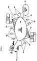
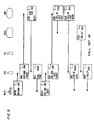
- the infrastructure of the inventive cellular switching system can be viewed as a wide area network (WAN) 200 linking base stations, public switches 201, and a cellular control unit 202.
- Information may enter and leaves the WAN through cellular interface units including base station interface units (BIU) 203; trunk interface units (TIU) 204, each connected to a central office trunk 205 of the public network; and a controller interface unit, CIU 206, connected to the cellular control unit.
- BIU base station interface units
- TIU trunk interface units
- CIU controller interface unit
- the packet switching capability of a WAN works well with the Packet Reservation Multiple Access technique for information transfer between base stations and wireless terminals (D. J. Goodman, R. A. Valenzuela, K. T. Gayliard, and B. Ramamurthi, Packet Reservation Multiple Access for Local Wireless Communications, "Proc. 38th IEEE Vehicular Technology Conference", Philadelphia June 1988, pp. 701-706).
- PRMA offers an attractive combination of simple control, efficient bandwidth utilization, and robustness in the presence of wireless access channel impairments.
- WIU wireless terminal interface unit
- the WIU, BIU, TIU, and CIU of this embodiment organize information transfer among wireless terminals, base stations, central office trunks, and the cellular control unit, respectively.
- Each packet contains a source address and a destination address.
- the address is the permanent identifier of an interface unit.
- the address is a call control number associated with a particular communication session.
- the addressing procedures are discussed in Section III in the context of specific communication and control functions. In this Section we describe the capabilities of the interface units.
- the TIU accepts and delivers information in the standard format of the public network.
- the speech format for example, is 64 kb/s companded pulse code modulation.
- the TIU 204 converts this information to and from the format of the wireless access physical layer by means of transcoders 300 and channel coders 301 matched to the wireless access environment of the cellular switching system.
- Each cellular switching system can be customized for its own transmission environment (for example, urban mobile, indoor, or mobile satellite) by means of the transcoders and channel coders installed in the TIU's.
- An architecture that admits many terminal-base transmission technologies, each matched to a specific environment, may be important to the successful operation of future wireless access systems (E. S. K. Chien, D. J. Goodman, and J. E. Russell, Sr., Cellular Access Digital Network (CADN): Wireless Access to Networks of the Future, "IEEE Communications Magazine", Vol. 25, No. 6, June 1987, pp. 22-31).
- APN Cellular Access Digital Network
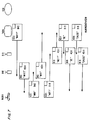
- the TIU may contain a packet assembler 302 and disassembler (PAD) 303.
- PAD combines user information or network control information, with a packet header.
- the header may contain flags, an error control field, a packet control field and an address field.
- the address of the TIU can be the permanent trunk identifier 304, or it can be a call control number 305 assigned by the cellular control unit.
- Packets sent from the TIU are routed to a base station by means of a portion of the address containing a permanent base station identifier 306. During a call this portion of the address changes to the permanent base station identifier of the new cell as the wireless terminal moves from the service area of one base station to another.
- the packet disassembler reads the destination address of all packets arriving on the WAN. When this address matches either the permanent trunk identifier (during call set up), or the call control number (during a call), the packet disassembler processes the arriving packet. If the packet has arrived from a base station, the TIU records the source address of the packet in its base station indentifier register 307. This identifier then becomes the destination address for packets launched into the WAN from the TIU.
- WIU Wireless Terminal Interface Unit
- the WIU is similar to the TIU. One difference is that the TIU receives user information from the public network, while the WIU generates its own user information, with, for example, a 64 kb/s analog-to-digital converter for speech signals. As indicated in Figure 4 the packet assembler of the WIU 207 delivers packets to the radio transmitter 400 by way of an exemplary PRMA protocol processor 401.
- the packet disassembler 402 compares the destination address of received packets with the either the permanent terminal identifier 403 (during call set up), or the call control number 404 (during a call). It extracts the information fields of speech packets destined for this terminal and converts them to a continuous 64 kb/s signal stream.
- the WIU refers to a channel quality monitor 405 to determine a base station identifier 406. This monitor indicates the identity of the base station best able to serve the terminal in its current location. This base station becomes the destination of packets sent from the wireless terminal.
- This unit relays information between the TIU's and the wireless terminals. It also broadcasts, over its radio channel, the acknowledgement packets called for by the exemplary PRMA protocol (D. J. Goodman, R. A. Valenzuela, K. T. Gayliard, and B. Ramamurthi, Packet Reservation Multiple Access for Local Wireless Communications, "Proc. 38th IEEE Vehicular Technology Conference", Phil., June 1988, pp. 701-708).
- the BIU multiplexes information packets that are sent to the radio transmitter. It also queues upstream packets for transmission over the WAN.
- the BIU may always be addressed by its permanent identifier. If an incoming packet arrives with a call control number in its address field, this number becomes the destination address when the packet is relayed, either to a TIU (upstream packet), or to a WIU (downstream packet). Certain network control packets arrive without call control numbers. These packets are either relayed to the cellular control unit; or, they are relayed to a WIU by means of the permanent identifier of the WIU. This identifier is extracted from the information field of the control packet. Examples of these routing procedures appear in Section m.
- the cellular control unit receives, processes, and generates network control packets. It may always be addressed by its permanent identifier. It assigns a control number to each cellular call, and sends this number to the TIU selected for the call, and to the relevant WIU. To distribute the call control number to the TIU, the CIU may use the permanent identifier of the TIU. To send the call control number to the WIU, the CIU may place the base station identifier in the destination address field of a control packet, and the permanent terminal identifier in the information field of the control packet.
- conversational speech, handover, and terminal initiated call set up we show how the cellular switching system organizes the flow of user information and system control information.
- the source and destination addresses of each packet control the routing of the packet to the correct interface unit.
- terminals and trunks Prior to call set up, terminals and trunks are addressed by their permanent identifiers.
- the cellular control unit assigns to the call a call control number. This number may then become the address of both the TIU and the WIU involved in the call. Base stations and the cellular control unit may always be addressed by their permanent identifiers.
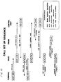
- FIGS. 9 and 10 show one possible scenario for a call set up in the cellular switching system.
- each packet is represented by a illustrative "postcard” in which the destination address is shown in the center righthand portion of the "postcard", the return or “source” address is shown in the upper lefthand portion of the "postcard” and the "information field” is shown in the center lefthand portion of the postcard.
- the horizontal direction represents location, with each interface unit represented by a column on the page, and the vertical direction represents time.
- FIGS. 6, 8 and 10 as in FIGS. 5, 7 and 9, the horizontal direction represents location and each interface unit is represented by a column on the page.
- the vertical direction represents time.
- the sequence of packet transfers is from top to bottom on the page.
- Each packet is indicated by a rectangle. The left side of the rectangle contains the source address of the packet. The right side contains the destination.
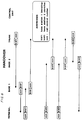
- FIGS. 9 and 10 there is shown a sequence of control packets leading to the transmission of the first speech packet ("Hello") from the public network to the wireless terminal.
- the addresses of each packet we also indicate, over the transmission arrow, the information content of the packet.
- the terminal sends an "off hook" message to the nearest base station.
- the base station relays the message, and the identity of the wireless terminal, to the cellular control unit.
- the controller uses the information in this message to authenticate the calling party. If the caller is authorized to place a call, the controller returns a "dial tone" message to the base station.
- the base station extracts the terminal identifier from the information field of the dial tone message and uses this identifier to relay dial tone to the WIU.
- the response to this message is a packet containing the called party's number. This enables the controller to attempt to establish a connection, through the local central office, to the called party.
- the controller When the connection is established, the controller issues a call control number to the WIU that initiated the call and to the TIU assigned to this call by the controller. With the call control number recorded in both the WIU and the TIU, the conversation proceeds as in FIGS. 5 and 6. Handovers, as necessary, take place as shown in FIGS. 7 and 8.
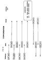
- FIGS. 5 and 6 illustrate such bidirectional flow of speech information.
- a conversation consists of a sequence of talkspurts alternating in direction, with each talkspurt containing several packets. The average number is about 60, but there is wide variability in the number of packets per talkspurt.
- the TIU and the WIU contain speech activity detectors (Fig.3 308; Fig.4 407) in this embodiment no packets need be generated in the silent gaps between talkspurts.
- FIGS. 7 and 8 are schematic representations of a handover protocol.
- the terminal initiates the handover by sending a packet to the new base station, "base 2", instead of "base 1", which received earlier packets.
- the speech packet is relayed to the central office trunk.
- the TIU learns the identity of the new base station and sends new packets to the terminal through base 2. If there has been no speech or other signals transmitted over an extended time period which includes the time that the subscriber crosses a cell boundary, then there is no way to determine that the call is best handled by a new base station. Accordingly an embodiment
- the cellular control unit may include regular transmission, either periodic or random, of packets substantially free of information other than the header information. These packets may be used to determine that the call can best be handled by a new base station, despite the fact that there is an absence of other transmissions. Because the cellular control unit plays no role in the handover process, its work load is unaffected by the volume of handovers. This volume can be very high in a microcellular system.
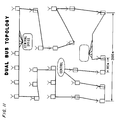
- FIG. 11 shows a hypothetical arrangement of base stations and central office switches in a cellular switching system service area of approximately four square kilometers.
- the service area contains two telephone switching offices and on the order of 50 base stations, placed approximately on a 300 meter grid.
- One cellular control unit serves the entire area.
- the dual bus topology is an open ring. In FIG. 11, the ring opening is located in the control unit.
- each PRMA packet can be designed to occupy exactly one slot on the dual bus.
- a nominal dual bus configuration operates at 150 Mb/s, with the bit stream organized in frames of duration 125 ms. With each frame containing 59 slots for user information, there are 38 bytes per slot.
- the PRMA protocol is also organized with slots and frames. If the total bit rate for speech information (source code plus channel code) is 16 kb/s, a PRMA packet of length 38 bytes, including 8 bytes of header information, implies a PRMA frame duration of 15 ms.
- the PRMA channel rate is 270 kb/s, and that the transmission bandwidth is 200 kHz. These are the bit rate and bandwidth of the Pan-European digital mobile radio system (J. Uddenfeldt and B. Persson, A Narrowband TDMA System for a New Generation Cellular Radio, "Proc. 37th IEEE Vehicular Technology Conference", Tampa, June 1987, pp. 286-292. Then we find that each PRMA channel supports more than 20 simultaneous conversations. Allowing five PRMA channels (frequency multiplexed) per cell, we have each base station capable of carrying 100 simultaneous conversations. Thus, the fifty base stations in Figure 8 have a capacity of 5000 simultaneous conversations, while the dual bus WAN can handle the equivalent of 7080 conversations. The extra WAN capacity will easily accommodate the required volume of network control packets.
- the 100 conversations per cell is equivalent to approximately 85 erlangs of traffic with a blocking probability of 0.01. Each cell, therefore, supports 85 erlangs in a bandwidth of 1 MHz. If the cellular reuse factor is seven, the total system bandwidth is 7 MHz per direction, with 4250 erlangs carried in the 4 km2 service area of the cellular switching system. The cellular efficiency is, therefore, 76 erlangs/ km2/MHz, which is two orders of magnitude higher than the efficiency of present cellular systems.
Description
- This invention relates to methods of routing information in a telecommunications switching systems, and has particularly useful application to cellular radio telecommunications.
- The commercial introduction of cellular radio telecommunications approximately five years ago is revolutionizing the telecommunications industry. The commercial interest in the cellular technique stems from its ability to enable high volume traffic to operate over the limited number of available radio channels. This is accomplished by dividing large geographical areas into smaller geographical areas, or cells. This permits the reuse of the same radio channels in different cells which are sufficiently separated spatially so as to avoid interference. Consequently, a large geographical area which previously had been limited to, for example, 700 channels, and consequently, to 700 telephone calls, could now be divided into, for example, 70 cells, each one of which could use a channel set comprising 100 channels, without interference from adjacent cells which are using different 100-channel sets. Consequently, 7,000 telephone calls can now be made from the large geographical area which previously had been limited to 700 telephone calls. This new architecture is effected by introducing appropriate telephone switches which enable the system to maintain the integrity of each telephone call as the source of the telephone call moves from one of the cells to another of the cells. To accomplish this, the system assigns a new frequency to a mobile telephone as it moves from one call to another, and assigns appropriate resources to route the signal from the new cell to the switch itself. Clearly, sophisticated routing and switching equipment, including appropriate software, had to be designed and developed to implement this architecture.
- As cellular radio becomes more popular, the cells become saturated due to the presence of more active subscribers within a given cell than there are available frequencies. However, cellular radio has within it an inherent technique for dealing with such an increase in subscribers. This technique is called cell splitting. in implementing cell splitting, the size of the cell is reduced, thereby once again bringing the number of active subscribers within each cell to a number less than or equal to the number of available frequencies. However, the explosive growth of demand for cellular radio makes it apparent that the cell splitting technique will soon become ineffective. This ineffectiveness is not associated with some inherent limitation on the size of the cells, but rather is associated with limitations of the switching machines, which, as the cells become smaller and smaller, have a greater demand placed on them because of the increased frequency with which active subscribers cross cell boundaries. Clearly, every time an active subscriber crosses a cell boundary the switching machine must hand over the call, i.e., assign a new frequency to the mobile terminal and assign resources to connect the signal from the new cell to the switch. Larger switching machines may be able to handle this increased traffic volume. However, they are much more expensive and may not be readily available because of the explosive demand for cellular radio apparatus. Thus a new cellular radio architecture and infra-structure would permit rapid growth by distributing many of the switching and control functions into small modulator units which can be easily added to the system as it grows.
- To understand the basic philosophy and operation of the invention, it is helpful to understand the basic underlying principles of the classic circuit switch, the packet switch, and the virtual circuit packet switch.
- The classic circuit switch involves an architecture which dedicates resources, including transmission resources, to each call, for the duration of the call. In circuit switching architecture, as it is applied to cellular radio, when the caller crosses a call boundary the cellular switch must release the resources that had previously been assigned to the given call, and must dedicate new resources to the call, thereby performing many of the functions characteristic of terminating a call and establishing a new call. Essentially all of the commercialized cellular radio architectures are circuit switch architectures, and, because of the heavy burden that such architectures place on the switch, these architectures rapidly saturate the switches as the cells are split time and again to meet increasing demand. Cell splitting increases the burden on the switch because as the cells are split the frequency of boundary crossing increases. (It is understood that the term "call" as used here, and the invention in general, is not limited to transmissions representing audio communications, but rather includes any type of communication including the transmission of data, facsimile, audio, video, etc.)
- The pure packet switch architecture in some sense is the direct opposite of the circuit switch architecture, in that the pure packet switch architecture never permanently assigns transmission resources to a given call. Rather, the information being transmitted in the call is divided into packets of information, each one of which is assigned transmission resources based on "header" information associated with each packet, and is routed independently of the other packets of information. Clearly, the advantage of the packet switch architecture is that since transmission resources are not dedicated to any given call, such resources may be used for other calls when the information transmitted by a call is "bursty" rather than steady. The transmission resources can be used for other calls during the idle time periods between the bursts of information. The disadvantage of the packet switch architecture is that it places a heavy burden on the switch, since the switch must establish routing for each packet, unlike the circuit switch architecture which establishes "permanent" routing once for each call. The advantage of packet switching comes at the expense of bandwidth since each packet must contain the necessary "header" information which conveys to the switch the routing requirements of each packet.
- In a sense, the advantages of the packet switch architecture and the circuit switch architecture are combined in the virtual circuit packet switch. In the virtual circuit packet switch architecture, the virtual circuit packet switch, like the circuit switch, establishes a route for each call at the beginning of the call. This route is stored in the memory of the switch. Thereafter, each packet contains in its header a call identification number, rather than more complete header information, which enables the switch to find in its memory the correct route for that call. In this manner, the switch does not have to go through the entire routing procedure in order to transmit each packet of a given call, but rather can rely on the previous routing procedure that had been established at the inception of the call. Although virtual circuit packet switching may be applied to cellular radio, switching must still occur as the active subscriber crosses each cell boundary. Consequently, in a very real sense, conventional virtual circuit packet switching offers little relief to the switch from the burdens associated with the increasing frequency of boundary crossings as the cells become smaller.
- EP-A-0 224 229 provides a mechanism to re-route data packets when an established route is interrupted due to failures or congestions in the existing route, but as the transceiver does not change its position in the network it fails to deal with specific dynamic routing problems.
- According to one aspect of this invention there is provided a method for routing information as claimed in
claim 1. - According to another aspect of this invention there is provided a method for routing information as claimed in
claim 2. - A new switching system and architecture is particularly effective in addressing the problem of increased switching burden due to the increasing frequency of boundary crossings as cellular radio cells become smaller. An aspect of the invention lies in the realization that routing information, associated with packets originating, for example, in an embodiment involving cellular calls, can be divided into information which does not change as the active subscriber crosses a cell boundary, and information which does change as the active subscriber crosses a cell boundary. Routing procedures associated with the information which does not change as the active subscriber crosses a cell boundary are established and may be stored in the memory of the switch, only once, at the beginning of the call, as in the circuit switch architecture. However, the routing procedures associated with the information which does changes as the active subscriber crosses a cell boundary may be derived from the header information of each packet that arrives at the appropriate portion of the switch. In this way the dynamic characteristics of a packet switch enable the architecture to adapt to very frequent crossings of cell boundaries by active subscribers, but at minimum increased burden to the switch. In an embodiment, interface units derive routing information from packet address fields and control the flow of information without the intervention of a central controller. Specific embodiments may also involve storage of this information, as well, until the cell boundary is crossed.
- An embodiment includes means for establishing an initial route for transmitting a number of packets of information between a first party and a second party. Each of the packets comprises a header which contains both information associated with a terminal of the first party, and information associated with a terminal of the second party.
- As indicated above, the established route comprises at least two segments. One of the segments of the route has associated with it constant routing information which is stored in a memory portion of the system. This routing information remains constant during transmission of the packets, and the headers of the packets have portions associated with this constant routing information. These portions of the headers also remain constant during the transmission of the packets.
- However, as also indicated above, a second segment of the route may vary during transmission of the packets. This segment therefore has associated with it varying routing information. The headers of the packets have portions associated with this varying routing information as well. These portions also may vary from one packet to another during transmission of the packets, corresponding to the varying routing information. Finally, the system has means for varying these latter portions of the header, in a manner representative of the second segment of the route.
- Current cellular switches establish both the initial route, and the new routes required every time a cell boundary is crossed. However, in contradistinction to these current cellular switches, this system may have two separate units, one of which establishes the initial route, and another one of which is used to vary only that portion of the header which changes as a cell boundary is crossed.
- While the discussion has been in terms of cells and variations which occur as cell boundaries are crossed, it is clear that the invention may be applied to other applications which also require the varying of only a portion of the route during the transmission of a number of packets. Such applications may include, for example, the varying of a portion of the route in response to malfunctions.
- As the public switched network evolves from a voice telephone network to a generalized information network, attention is increasingly focused on packet switching technologies, including pure packet switching and virtual circuit packet switching. This evolution of the public network, as well as the ability of packet switching to deal with the increasing burdens of an expanding cellular network, makes the application of packet-type switching, as in this invention, even more attractive to cellular technology.
-
- FIG. 1 is a schematic representation of a prior art cellular telecommunication system;
- FIG. 2 is a schematic representation of an embodiment of a new telecommunication switching system involving cellular switching;
- FIG. 3 is a schematic representation of an exemplary cellular trunk interface unit (TIU) which may be used in the cellular switching system;
- FIG. 4 is a schematic representation of an exemplary cellular wireless terminal interface unit (WIU) which may be used in the cellular switching system;
- FIGS. 5 and 6 are schematic representations of a conversation using the cellular switching system;
- FIGS. 7 and 8 are schematic representations of a handover protocol using the cellular switching system;
- FIGS. 9 and 10 are schematic representations of a call setup sequence using the cellular switching system; and
- FIG. 11 is a schematic representation of a dual bus protocol embodiment of the cellular switching system.
- In order to provide wireless access to public networks, current cellular systems contain wireless terminals, base stations, and at least one cellular switch. As shown schematically in FIG. 1, the
switch 100 is connected to an ensemble ofbase stations 101. Each base station is in radio contact with many wireless terminals102. The system infrastructure is the combination of hardware and software that links base stations with cellular switches, and cellular switches with one another. - The complexity of a cellular system is due in large part to the mobility of the wireless terminals. Unlike fixed networks, cellular systems require frequent changes in configuration. To establish each call, the system has to learn the location of a wireless terminal; and, it must be able to adapt itself to one or more changes in terminal location during the call.
- Many network control functions are unique to cellular networks. Some are not necessary in fixed networks, and others are performed differently in cellular and fixed networks. Examples include: authentication, location updating, paging, call set-up, call release, power control, and handover. In present cellular systems, these functions are primarily tasks of the cellular switches.
- It is anticipated that future systems will serve a much higher population of users than present systems. As a consequence, cells will be considerably smaller than at present and the volume of network rearrangements, necessary each time the subscriber crosses a cell boundary, (location updating, power control, and handover) will grow by orders of magnitude. This volume will overwhelm the control capacity of present cellular switches.
- To provide the necessary control, an embodiment, as applied to cellular switching systems, exploits packet communication technology to distribute network information among small processors (interface units) residing in all network elements. It uses the address field of each packet to provide routing information corresponding to the changing location of the wireless terminal.
- As indicted in Figure 2, the infrastructure of the inventive cellular switching system can be viewed as a wide area network (WAN) 200 linking base stations,
public switches 201, and acellular control unit 202. Information may enter and leaves the WAN through cellular interface units including base station interface units (BIU) 203; trunk interface units (TIU) 204, each connected to acentral office trunk 205 of the public network; and a controller interface unit,CIU 206, connected to the cellular control unit. - The packet switching capability of a WAN works well with the Packet Reservation Multiple Access technique for information transfer between base stations and wireless terminals (D. J. Goodman, R. A. Valenzuela, K. T. Gayliard, and B. Ramamurthi, Packet Reservation Multiple Access for Local Wireless Communications, "Proc. 38th IEEE Vehicular Technology Conference", Philadelphia June 1988, pp. 701-706). As a statistical multiplexer, PRMA offers an attractive combination of simple control, efficient bandwidth utilization, and robustness in the presence of wireless access channel impairments. To marry PRMA to the inventive cellular switching system, we may introduce to each terminal a wireless terminal interface unit (WIU) 207.
- The WIU, BIU, TIU, and CIU of this embodiment organize information transfer among wireless terminals, base stations, central office trunks, and the cellular control unit, respectively. Each packet contains a source address and a destination address. Sometimes the address is the permanent identifier of an interface unit. At other times, the address is a call control number associated with a particular communication session. The addressing procedures are discussed in Section III in the context of specific communication and control functions. In this Section we describe the capabilities of the interface units.
- The TIU accepts and delivers information in the standard format of the public network. The speech format, for example, is 64 kb/s companded pulse code modulation. As indicated in FIG. 3, the
TIU 204 converts this information to and from the format of the wireless access physical layer by means oftranscoders 300 andchannel coders 301 matched to the wireless access environment of the cellular switching system. Each cellular switching system can be customized for its own transmission environment (for example, urban mobile, indoor, or mobile satellite) by means of the transcoders and channel coders installed in the TIU's. An architecture that admits many terminal-base transmission technologies, each matched to a specific environment, may be important to the successful operation of future wireless access systems (E. S. K. Chien, D. J. Goodman, and J. E. Russell, Sr., Cellular Access Digital Network (CADN): Wireless Access to Networks of the Future, "IEEE Communications Magazine", Vol. 25, No. 6, June 1987, pp. 22-31). - In addition to transforming user information between the formats of the fixed network and the wireless access channels, the TIU may contain a
packet assembler 302 and disassembler (PAD) 303. Each PAD combines user information or network control information, with a packet header. The header may contain flags, an error control field, a packet control field and an address field. The address of the TIU can be thepermanent trunk identifier 304, or it can be acall control number 305 assigned by the cellular control unit. Packets sent from the TIU are routed to a base station by means of a portion of the address containing a permanentbase station identifier 306. During a call this portion of the address changes to the permanent base station identifier of the new cell as the wireless terminal moves from the service area of one base station to another. - In Figure 3, the packet disassembler reads the destination address of all packets arriving on the WAN. When this address matches either the permanent trunk identifier (during call set up), or the call control number (during a call), the packet disassembler processes the arriving packet. If the packet has arrived from a base station, the TIU records the source address of the packet in its base
station indentifier register 307. This identifier then becomes the destination address for packets launched into the WAN from the TIU. - In generating packets, the WIU is similar to the TIU. One difference is that the TIU receives user information from the public network, while the WIU generates its own user information, with, for example, a 64 kb/s analog-to-digital converter for speech signals. As indicated in Figure 4 the packet assembler of the
WIU 207 delivers packets to theradio transmitter 400 by way of an exemplaryPRMA protocol processor 401. - As in the TIU, the
packet disassembler 402 compares the destination address of received packets with the either the permanent terminal identifier 403 (during call set up), or the call control number 404 (during a call). It extracts the information fields of speech packets destined for this terminal and converts them to a continuous 64 kb/s signal stream. - In order to implement terminal initiated handover, the WIU refers to a channel quality monitor 405 to determine a
base station identifier 406. This monitor indicates the identity of the base station best able to serve the terminal in its current location. This base station becomes the destination of packets sent from the wireless terminal. - This unit relays information between the TIU's and the wireless terminals. It also broadcasts, over its radio channel, the acknowledgement packets called for by the exemplary PRMA protocol (D. J. Goodman, R. A. Valenzuela, K. T. Gayliard, and B. Ramamurthi, Packet Reservation Multiple Access for Local Wireless Communications, "Proc. 38th IEEE Vehicular Technology Conference", Phil., June 1988, pp. 701-708). The BIU multiplexes information packets that are sent to the radio transmitter. It also queues upstream packets for transmission over the WAN.
- The BIU may always be addressed by its permanent identifier. If an incoming packet arrives with a call control number in its address field, this number becomes the destination address when the packet is relayed, either to a TIU (upstream packet), or to a WIU (downstream packet). Certain network control packets arrive without call control numbers. These packets are either relayed to the cellular control unit; or, they are relayed to a WIU by means of the permanent identifier of the WIU. This identifier is extracted from the information field of the control packet. Examples of these routing procedures appear in Section m.
- The cellular control unit receives, processes, and generates network control packets. It may always be addressed by its permanent identifier. It assigns a control number to each cellular call, and sends this number to the TIU selected for the call, and to the relevant WIU. To distribute the call control number to the TIU, the CIU may use the permanent identifier of the TIU. To send the call control number to the WIU, the CIU may place the base station identifier in the destination address field of a control packet, and the permanent terminal identifier in the information field of the control packet.
- By referring to three examples: conversational speech, handover, and terminal initiated call set up, we show how the cellular switching system organizes the flow of user information and system control information. The source and destination addresses of each packet control the routing of the packet to the correct interface unit. Prior to call set up, terminals and trunks are addressed by their permanent identifiers. In setting up a call, the cellular control unit assigns to the call a call control number. This number may then become the address of both the TIU and the WIU involved in the call. Base stations and the cellular control unit may always be addressed by their permanent identifiers.
- FIGS. 9 and 10 show one possible scenario for a call set up in the cellular switching system. (In FIG. 9, as in FIGS. 5 and 7, each packet is represented by a illustrative "postcard" in which the destination address is shown in the center righthand portion of the "postcard", the return or "source" address is shown in the upper lefthand portion of the "postcard" and the "information field" is shown in the center lefthand portion of the postcard. In these FIGS., the horizontal direction represents location, with each interface unit represented by a column on the page, and the vertical direction represents time. In FIGS. 6, 8 and 10, as in FIGS. 5, 7 and 9, the horizontal direction represents location and each interface unit is represented by a column on the page. The vertical direction represents time. The sequence of packet transfers is from top to bottom on the page. Each packet is indicated by a rectangle. The left side of the rectangle contains the source address of the packet. The right side contains the destination.)
- In FIGS. 9 and 10 there is shown a sequence of control packets leading to the transmission of the first speech packet ("Hello") from the public network to the wireless terminal. In addition to the addresses of each packet, we also indicate, over the transmission arrow, the information content of the packet.
- First the terminal sends an "off hook" message to the nearest base station. The base station relays the message, and the identity of the wireless terminal, to the cellular control unit. The controller uses the information in this message to authenticate the calling party. If the caller is authorized to place a call, the controller returns a "dial tone" message to the base station. The base station extracts the terminal identifier from the information field of the dial tone message and uses this identifier to relay dial tone to the WIU. The response to this message is a packet containing the called party's number. This enables the controller to attempt to establish a connection, through the local central office, to the called party.
- When the connection is established, the controller issues a call control number to the WIU that initiated the call and to the TIU assigned to this call by the controller. With the call control number recorded in both the WIU and the TIU, the conversation proceeds as in FIGS. 5 and 6. Handovers, as necessary, take place as shown in FIGS. 7 and 8.
- As long as the wireless terminal remains in a single cell, packets move from terminal to base station to central office trunk (and in the opposite direction) in a straightforward manner. FIGS. 5 and 6 illustrate such bidirectional flow of speech information. Generally a conversation consists of a sequence of talkspurts alternating in direction, with each talkspurt containing several packets. The average number is about 60, but there is wide variability in the number of packets per talkspurt. Because the TIU and the WIU contain speech activity detectors (Fig.3 308; Fig.4 407) in this embodiment no packets need be generated in the silent gaps between talkspurts.
- The Cellular Switching System hands a call from one base station to another when the wireless terminal determines that the call can best be handled by the new base station. FIGS. 7 and 8 are schematic representations of a handover protocol. As indicated in FIGS. 6 and 7, the terminal initiates the handover by sending a packet to the new base station, "
base 2", instead of "base 1", which received earlier packets. The speech packet is relayed to the central office trunk. There, the TIU learns the identity of the new base station and sends new packets to the terminal throughbase 2. If there has been no speech or other signals transmitted over an extended time period which includes the time that the subscriber crosses a cell boundary, then there is no way to determine that the call is best handled by a new base station. Accordingly an embodiment - may include regular transmission, either periodic or random, of packets substantially free of information other than the header information. These packets may be used to determine that the call can best be handled by a new base station, despite the fact that there is an absence of other transmissions. Because the cellular control unit plays no role in the handover process, its work load is unaffected by the volume of handovers. This volume can be very high in a microcellular system.
- This section considers a dual bus protocol (J. F. Mollenauer, Standards for Metropolitan Area Networks, "IEEE Communications Magazine", Vol. 26, No. 4, April 1988, pp. 15-19; and R. M. Newman, Z. L. Budrikis, and J. L. Hullett, The QPSX Man, "IEEE Communications Magazine", Vol. 26, No. 4, April 1988, pp. 20-28) as one possible realization of the Wide Area Network in Figure 2. Sometimes referred to as QPSX, this new Standard 802.6. FIG. 11 shows a hypothetical arrangement of base stations and central office switches in a cellular switching system service area of approximately four square kilometers. The service area contains two telephone switching offices and on the order of 50 base stations, placed approximately on a 300 meter grid. One cellular control unit serves the entire area. The dual bus topology is an open ring. In FIG. 11, the ring opening is located in the control unit.
- For operation with a simplified version of the dual bus protocol, each PRMA packet can be designed to occupy exactly one slot on the dual bus. A nominal dual bus configuration operates at 150 Mb/s, with the bit stream organized in frames of duration 125 ms. With each frame containing 59 slots for user information, there are 38 bytes per slot. The PRMA protocol is also organized with slots and frames. If the total bit rate for speech information (source code plus channel code) is 16 kb/s, a PRMA packet of length 38 bytes, including 8 bytes of header information, implies a PRMA frame duration of 15 ms.
- This means that during a talk spurt, a terminal or a trunk will generate one packet for every 120 (=15 ms/125 ms) dual bus frames. Therefore, the capacity of the dual bus is 59x120=7080 simultaneous conversations, assuming that, on average, a conversation produces one packet per PRMA frame. (This is a conservative. Measurements indicate that the long-term average is typically 0.72 to 0.86 packets per frame depending on the sensitivity of the speech activity detector.)
- Let us assume that the PRMA channel rate is 270 kb/s, and that the transmission bandwidth is 200 kHz. These are the bit rate and bandwidth of the Pan-European digital mobile radio system (J. Uddenfeldt and B. Persson, A Narrowband TDMA System for a New Generation Cellular Radio, "Proc. 37th IEEE Vehicular Technology Conference", Tampa, June 1987, pp. 286-292. Then we find that each PRMA channel supports more than 20 simultaneous conversations. Allowing five PRMA channels (frequency multiplexed) per cell, we have each base station capable of carrying 100 simultaneous conversations. Thus, the fifty base stations in Figure 8 have a capacity of 5000 simultaneous conversations, while the dual bus WAN can handle the equivalent of 7080 conversations. The extra WAN capacity will easily accommodate the required volume of network control packets.
- The 100 conversations per cell is equivalent to approximately 85 erlangs of traffic with a blocking probability of 0.01. Each cell, therefore, supports 85 erlangs in a bandwidth of 1 MHz. If the cellular reuse factor is seven, the total system bandwidth is 7 MHz per direction, with 4250 erlangs carried in the 4 km2 service area of the cellular switching system. The cellular efficiency is, therefore, 76 erlangs/ km2/MHz, which is two orders of magnitude higher than the efficiency of present cellular systems.
Claims (3)
- A method for routing information in a telecommunications switching system comprising means for establishing a route comprised of at least two segments for transmitting a number of packets of information between a first party and a second party, wherein each packet comprises a header containing information associated with a terminal of the first party, and information associated with a terminal of the second party, the method being characterized by the steps of storing, in a memory means (304) within said system, header information associated with a first route segment (304,305) over which said number of packets are to be transmitted, said first segment routing header information being held constant during transmission of said number of packets,establishing a first route segment in accordance with said stored first segment routing header information; and,generating header information indicative of a second route segment (306) over which said number of packets are to be transmitted, said second segment routing header information being variable from header to header during transmission of the said number of packets.
- A method for routing information in a telecommunications switching system comprising means for establishing a route comprised of at least two segments for transmitting a number of packets of information between a first party and a second party, wherein each packet comprises a header containing information associated with a terminal of the first party, and information associated with a terminal of the second party, the method being characterized by the steps of:receiving said number of packets of information from said terminal of said first party;disassembling (303) said received packet to obtain the destination address encoded within said information contained within said headers of said number of packets;storing, in a memory means (304) within said system, header information associated with a first route segment (304, 305) over which said number of packets are to be transmitted, said first segment routing header information being held constant during transmission of said number of packets,establishing a first route segment in accordance with said stored first segment routing header information; and,generating header information indicative of a second route segment (306) over which said number of packets are to be transmitted, said second segment routing header information being variable from header to header during transmission of the said number of packets; andassembling (302) a packet header indicative of said variable header information.
- A method as claimed in claim 1 or 2 wherein the routing header information associated with the second route segment is varied in response to a change in the geographical location of one of the parties.
Applications Claiming Priority (2)
| Application Number | Priority Date | Filing Date | Title |
|---|---|---|---|
| US07/263,928 US4916691A (en) | 1988-10-28 | 1988-10-28 | Telecommunications switching system |
| US263928 | 1988-10-28 |
Publications (3)
| Publication Number | Publication Date |
|---|---|
| EP0366342A2 EP0366342A2 (en) | 1990-05-02 |
| EP0366342A3 EP0366342A3 (en) | 1991-12-27 |
| EP0366342B1 true EP0366342B1 (en) | 1996-01-24 |
Family
ID=23003849
Family Applications (1)
| Application Number | Title | Priority Date | Filing Date |
|---|---|---|---|
| EP89310696A Expired - Lifetime EP0366342B1 (en) | 1988-10-28 | 1989-10-18 | Method for routing information in a telecommunications switching system |
Country Status (6)
| Country | Link |
|---|---|
| US (1) | US4916691A (en) |
| EP (1) | EP0366342B1 (en) |
| JP (1) | JPH0771112B2 (en) |
| CA (1) | CA2000558C (en) |
| DE (1) | DE68925513T2 (en) |
| HK (1) | HK145096A (en) |
Cited By (1)
| Publication number | Priority date | Publication date | Assignee | Title |
|---|---|---|---|---|
| US8195188B2 (en) | 1997-08-04 | 2012-06-05 | Enovsys Llc | Location reporting satellite paging system with optional blocking of location reporting |
Families Citing this family (85)
| Publication number | Priority date | Publication date | Assignee | Title |
|---|---|---|---|---|
| IL89461A (en) * | 1989-03-02 | 1994-06-24 | Eci Telecom Limited | Facsimile telecommunication compression system |
| GB8909362D0 (en) * | 1989-04-25 | 1989-06-14 | British Telecomm | High gain semiconductor laser amplifier package |
| GB8910085D0 (en) * | 1989-05-03 | 1989-06-21 | British Telecomm | Mobile communications system |
| GB8913931D0 (en) * | 1989-06-16 | 1989-08-02 | Ferranti Creditphone | Cordless pbx |
| US5860136A (en) * | 1989-06-16 | 1999-01-12 | Fenner; Peter R. | Method and apparatus for use of associated memory with large key spaces |
| US6389010B1 (en) * | 1995-10-05 | 2002-05-14 | Intermec Ip Corp. | Hierarchical data collection network supporting packetized voice communications among wireless terminals and telephones |
| US5673252A (en) * | 1990-02-15 | 1997-09-30 | Itron, Inc. | Communications protocol for remote data generating stations |
| US5384826A (en) * | 1990-10-01 | 1995-01-24 | At&T Bell Laboratories | Distributed packetized switching cellular radio telephone communication system with handoff |
| US5371780A (en) * | 1990-10-01 | 1994-12-06 | At&T Corp. | Communications resource assignment in a wireless telecommunications system |
| WO1992007434A1 (en) * | 1990-10-23 | 1992-04-30 | Omnipoint Corporation | Method and apparatus for establishing spread spectrum communications |
| US5703881A (en) * | 1990-12-06 | 1997-12-30 | Hughes Electronics | Multi-subscriber unit for radio communication system and method |
| US6847611B1 (en) | 1990-12-10 | 2005-01-25 | At&T Corp. | Traffic management for frame relay switched data service |
| US5274802A (en) * | 1991-02-22 | 1993-12-28 | Gte Mobilnet Incorporated | Method for restoring lost databases by comparing existing database and generic database, and generating cellular switch commands to update the generic database |
| CA2040234C (en) * | 1991-04-11 | 2000-01-04 | Steven Messenger | Wireless coupling of devices to wired network |
| US5195090A (en) | 1991-07-09 | 1993-03-16 | At&T Bell Laboratories | Wireless access telephone-to-telephone network interface architecture |
| CA2066538C (en) * | 1991-07-09 | 1997-12-23 | Brian David Bolliger | Mobile-telephone system call processing arrangement |
| EP0596913B1 (en) * | 1991-07-19 | 1998-09-09 | Itron, Inc. | Wide area communications network for remote data generating stations |
| US5488653A (en) * | 1991-09-04 | 1996-01-30 | Comsat Corporation | Facsimile interface unit (FIU) enhanced capabilities negotiation |
| US5291492A (en) * | 1991-12-18 | 1994-03-01 | Unifi Communications Corporation | Externally controlled call processing system |
| US5517618A (en) | 1992-02-10 | 1996-05-14 | Matsushita Electric Industrial Co., Ltd. | Mobile migration communications control device |
| EP0592623A1 (en) * | 1992-03-21 | 1994-04-20 | Roke Manor Research Limited | Atm radio network |
| US5396490A (en) * | 1992-03-23 | 1995-03-07 | Motorola, Inc. | Packet reassembly method and apparatus |
| EP0577960B1 (en) * | 1992-06-24 | 2004-04-28 | Siemens Aktiengesellschaft | Improvements relating to mobile radio networks |
| FI96565C (en) * | 1992-06-30 | 1996-07-10 | Nokia Telecommunications Oy | Small Cell Radio Network |
| FI92274C (en) * | 1993-01-11 | 1994-10-10 | Nokia Telecommunications Oy | Call control device in a digital TDMA radio system and in its terminal device as well as a TDMA radio system and a semi-duplex terminal device |
| GB2276292B (en) * | 1993-03-17 | 1997-01-08 | Roke Manor Research | Improvements in or relating to communication systems |
| US6771617B1 (en) | 1993-06-17 | 2004-08-03 | Gilat Satellite Networks, Ltd. | Frame relay protocol-based multiplex switching scheme for satellite mesh network |
| US5434850A (en) | 1993-06-17 | 1995-07-18 | Skydata Corporation | Frame relay protocol-based multiplex switching scheme for satellite |
| US5440545A (en) * | 1993-08-02 | 1995-08-08 | Motorola, Inc. | Packet delivery system |
| CA2123736C (en) * | 1993-10-04 | 1999-10-19 | Zygmunt Haas | Packetized cellular system |
| SE9304119D0 (en) * | 1993-12-10 | 1993-12-10 | Ericsson Ge Mobile Communicat | Devices and mobile stations for providing packaged data communication in digital TDMA cellular systems |
| SE515361C2 (en) * | 1993-12-22 | 2001-07-23 | Eritel Ab | Transmission of spoken messages |
| FI95984C (en) * | 1994-04-08 | 1996-04-10 | Nokia Telecommunications Oy | Method and arrangement for location management in connection with packet data transmission in a mobile communication system |
| US5537679A (en) * | 1994-08-01 | 1996-07-16 | Motorola, Inc. | Communication network with flexible handoff scheduling for mobile nodes |
| US5606595A (en) * | 1994-08-19 | 1997-02-25 | Lucent Technologies Inc. | Equal access to inter-exchange carriers in a mobile wireless packet data communication system |
| US5539744A (en) * | 1994-10-17 | 1996-07-23 | At&T Corp. | Hand-off management for cellular telephony |
| US5784362A (en) * | 1995-04-17 | 1998-07-21 | Telefonaktiebolaget Lm Ericsson | Temporary frame identification for ARQ in a reservation-slotted-ALOHA type of protocol |
| US5907555A (en) * | 1995-10-18 | 1999-05-25 | Telefonaktiebolaget Lm Ericsson | Method for compensating for time dispersion in a communication system |
| US5806007A (en) * | 1995-10-18 | 1998-09-08 | Telefonaktiebolaget Lm Ericsson | Activity control for a mobile station in a wireless communication system |
| US5910949A (en) * | 1995-10-18 | 1999-06-08 | Telefonaktiebolaget Lm Ericsson | Packet channel feedback |
| US5845215A (en) * | 1995-10-18 | 1998-12-01 | Telefonaktiebolaget Lm Ericsson | Operating mobile stations of wireless communication systems in multiple modes by external control |
| US5903552A (en) * | 1995-10-18 | 1999-05-11 | Telefonaktiebolaget Lm Ericsson | Discriminating between channels in wireless communication systems |
| US6091960A (en) * | 1995-10-18 | 2000-07-18 | Telefonaktiebolaget Lm Ericsson | Method for paging mobile stations |
| US6018661A (en) * | 1995-10-18 | 2000-01-25 | Telefonaktiebolaget Lm Ericsson | Inhibiting and controlling signal strength measurements by a mobile station in a wireless communication system |
| US5768267A (en) * | 1995-10-18 | 1998-06-16 | Telefonaktiebolaget Lm Ericsson | Method for system registration and cell reselection |
| US5818829A (en) * | 1995-10-18 | 1998-10-06 | Telefonaktiebolaget Lm Ericsson | Method for increasing throughput capacity in a communication system |
| US5751731A (en) * | 1995-10-18 | 1998-05-12 | Telefonaktiebolaget Lm Ericsson | Simplifying decoding of codewords in a wireless communication system |
| US6044270A (en) * | 1995-10-18 | 2000-03-28 | Telefonaktiengesellschaft Lm Ericsson | Apparatuses and methods for signal strength measurement in a wireless communication system |
| US5757813A (en) * | 1995-10-18 | 1998-05-26 | Telefonaktiebolaget Lm Ericsson | Method for achieving optimal channel coding in a communication system |
| US6016428A (en) * | 1995-10-18 | 2000-01-18 | Telefonaktiebolaget Lm Ericsson | Registration control of mobile stations in a wireless communication system |
| US5729531A (en) * | 1995-10-18 | 1998-03-17 | Telefonaktiebolaget Lm Ericsson | Bandwidth allocation |
| US6577618B2 (en) | 1995-10-18 | 2003-06-10 | Telefonaktiebolaget L.M. Ericsson (Publ) | Packet control channel feedback support for contention and reservation based access |
| FI101763B1 (en) | 1995-12-01 | 1998-08-14 | Nokia Mobile Phones Ltd | The retention of the transported information composition between base station switches |
| FI102132B (en) * | 1995-12-01 | 1998-10-15 | Nokia Mobile Phones Ltd | Use of the ATM cell's title field in radio-mediated ATM communication |
| GB9603582D0 (en) | 1996-02-20 | 1996-04-17 | Hewlett Packard Co | Method of accessing service resource items that are for use in a telecommunications system |
| FI102654B (en) * | 1996-02-22 | 1999-01-15 | Nokia Mobile Phones Ltd | Method of replacing base station in a radio extension of the ATM network |
| US6069890A (en) * | 1996-06-26 | 2000-05-30 | Bell Atlantic Network Services, Inc. | Internet telephone service |
| US6154445A (en) | 1996-04-18 | 2000-11-28 | Bell Atlantic Network Services, Inc. | Telephony communication via varied redundant networks |
| US5923659A (en) | 1996-09-20 | 1999-07-13 | Bell Atlantic Network Services, Inc. | Telecommunications network |
| US6570871B1 (en) * | 1996-10-08 | 2003-05-27 | Verizon Services Corp. | Internet telephone service using cellular digital vocoder |
| US6359866B1 (en) | 1996-12-17 | 2002-03-19 | Telefonaktiebolaget Lm Ericsson (Publ) | Base station having transceivers used for communicating voice and packet data signals |
| US6078582A (en) | 1996-12-18 | 2000-06-20 | Bell Atlantic Network Services, Inc. | Internet long distance telephone service |
| US6839340B1 (en) | 1997-09-16 | 2005-01-04 | Bell Atlantic Network Services | Network session management |
| US6137869A (en) | 1997-09-16 | 2000-10-24 | Bell Atlantic Network Services, Inc. | Network session management |
| US6075783A (en) | 1997-03-06 | 2000-06-13 | Bell Atlantic Network Services, Inc. | Internet phone to PSTN cellular/PCS system |
| US6157648A (en) * | 1997-03-06 | 2000-12-05 | Bell Atlantic Network Services, Inc. | Network session management |
| US6542497B1 (en) * | 1997-03-11 | 2003-04-01 | Verizon Services Corp. | Public wireless/cordless internet gateway |
| US6574216B1 (en) * | 1997-03-11 | 2003-06-03 | Verizon Services Corp. | Packet data network voice call quality monitoring |
| US6292479B1 (en) | 1997-03-19 | 2001-09-18 | Bell Atlantic Network Services, Inc. | Transport of caller identification information through diverse communication networks |
| US6870827B1 (en) | 1997-03-19 | 2005-03-22 | Verizon Services Corp. | Voice call alternative routing through PSTN and internet networks |
| US6393014B1 (en) * | 1997-06-03 | 2002-05-21 | At&T Wireless Services, Inc. | Method and system for providing data communication with a mobile station |
| US7290288B2 (en) | 1997-06-11 | 2007-10-30 | Prism Technologies, L.L.C. | Method and system for controlling access, by an authentication server, to protected computer resources provided via an internet protocol network |
| FI105878B (en) | 1997-06-13 | 2000-10-13 | Nokia Networks Oy | Identifying the connection over an ATM protocol stack in a wireless telecommunications system transmission system |
| US6081524A (en) | 1997-07-03 | 2000-06-27 | At&T Corp. | Frame relay switched data service |
| US6147988A (en) * | 1997-10-27 | 2000-11-14 | Bell Atlantic Network Services, Inc. | IP packet switching in a Telco switch |
| FI106353B (en) * | 1998-01-09 | 2001-01-15 | Sonera Oyj | A method and system for changing a subscriber profile based on the identity of the base station serving the terminal |
| US6597680B1 (en) | 1998-11-16 | 2003-07-22 | Telefonaktiebolaget Lm Ericsson (Publ) | Packet traffic channel reassignment |
| US6885678B2 (en) | 1999-04-14 | 2005-04-26 | Verizon Services Corp. | Telecommunications network |
| EP1806947B1 (en) * | 1999-08-31 | 2009-10-21 | Lucent Technologies Inc. | System for handover in a cellular radio communication network |
| US6608828B1 (en) * | 1999-09-15 | 2003-08-19 | Ericsson Inc. | Methods and systems for decoding headers that are repeatedly transmitted and received along with data on a radio channel |
| US20010055391A1 (en) * | 2000-04-27 | 2001-12-27 | Jacobs Paul E. | System and method for extracting, decoding, and utilizing hidden data embedded in audio signals |
| GB0314793D0 (en) * | 2003-06-25 | 2003-07-30 | Hewlett Packard Development Co | Controlled download of data |
| US8515424B2 (en) * | 2004-06-01 | 2013-08-20 | Qualcomm Incorporated | Connected-state radio session transfer in wireless communication systems |
| RU2363107C2 (en) | 2004-06-01 | 2009-07-27 | Квэлкомм Инкорпорейтед | System and method of packet handover in wireless communication system |
| US8238538B2 (en) | 2009-05-28 | 2012-08-07 | Comcast Cable Communications, Llc | Stateful home phone service |
Family Cites Families (6)
| Publication number | Priority date | Publication date | Assignee | Title |
|---|---|---|---|---|
| DE3125189C2 (en) * | 1981-06-26 | 1984-06-14 | Erwin Sick Gmbh Optik-Elektronik, 7808 Waldkirch | Troubleshooting device for wide webs |
| US4797882A (en) * | 1985-10-02 | 1989-01-10 | American Telephone And Telegraph Company, At&T Bell Laboratories | Mesh-based switching network |
| US4679189A (en) * | 1985-11-27 | 1987-07-07 | American Telephone And Telegraph Company | Alternate routing arrangement |
| NL8601712A (en) * | 1986-07-01 | 1988-02-01 | Koninkl Philips Electronics Nv | COMMUNICATION NETWORK, IN PARTICULAR A TELEPHONE NETWORK AND DATA COMMUNICATION NETWORK COMPOSED OF A COLLECTION OF BUTTON UNITS, WHICH FOLLOWS SPECIFIC FACILITIES UNDER DUTIES. |
| US4823111A (en) * | 1988-02-22 | 1989-04-18 | The Mitre Corporation | Landmark hierarchy method for routing signals in a communications network |
| GB8910085D0 (en) * | 1989-05-03 | 1989-06-21 | British Telecomm | Mobile communications system |
-
1988
- 1988-10-28 US US07/263,928 patent/US4916691A/en not_active Expired - Lifetime
-
1989
- 1989-10-12 CA CA002000558A patent/CA2000558C/en not_active Expired - Fee Related
- 1989-10-18 DE DE68925513T patent/DE68925513T2/en not_active Expired - Fee Related
- 1989-10-18 EP EP89310696A patent/EP0366342B1/en not_active Expired - Lifetime
- 1989-10-27 JP JP27876389A patent/JPH0771112B2/en not_active Expired - Fee Related
-
1996
- 1996-08-01 HK HK145096A patent/HK145096A/en not_active IP Right Cessation
Cited By (1)
| Publication number | Priority date | Publication date | Assignee | Title |
|---|---|---|---|---|
| US8195188B2 (en) | 1997-08-04 | 2012-06-05 | Enovsys Llc | Location reporting satellite paging system with optional blocking of location reporting |
Also Published As
| Publication number | Publication date |
|---|---|
| DE68925513D1 (en) | 1996-03-07 |
| JPH0771112B2 (en) | 1995-07-31 |
| DE68925513T2 (en) | 1996-06-20 |
| JPH02244850A (en) | 1990-09-28 |
| EP0366342A2 (en) | 1990-05-02 |
| HK145096A (en) | 1996-08-09 |
| US4916691A (en) | 1990-04-10 |
| CA2000558A1 (en) | 1990-04-28 |
| EP0366342A3 (en) | 1991-12-27 |
| CA2000558C (en) | 1993-06-15 |
Similar Documents
| Publication | Publication Date | Title |
|---|---|---|
| EP0366342B1 (en) | Method for routing information in a telecommunications switching system | |
| US5384826A (en) | Distributed packetized switching cellular radio telephone communication system with handoff | |
| Goodman | Cellular packet communications | |
| US6353607B1 (en) | IP base GSM inter-MSC handover | |
| US6411810B1 (en) | Overload control in a packet-switching cellular environment | |
| EP0113662B1 (en) | Cellular mobile radio service telephone system | |
| EP0847174B1 (en) | Method and apparatus for data network call processing | |
| US6272358B1 (en) | Vocoder by-pass for digital mobile-to-mobile calls | |
| US5721762A (en) | Shared base stations for voice and data cellular telecommunications and method | |
| JPH09503634A (en) | Distributed telecommunications switching system | |
| HU216554B (en) | Local isdn radio transmission system | |
| JPH10224853A (en) | Communication network utilizing internet and its base station | |
| CA2289926A1 (en) | A method for packet switched data transmission | |
| CA2142020A1 (en) | Method and apparatus for transferring a radiotelephone call from one coverage area to another | |
| WO1997042771A3 (en) | A method and apparatus for providing different terminating call treatments based on service area | |
| EP0479477B1 (en) | Distributed switching cellular communication system | |
| US5999521A (en) | System and method for providing local services to a wireless telephone served by another system | |
| CA2188041A1 (en) | Multicellular transmission method and apparatus | |
| JP3096655B2 (en) | Wireless communication switching system for CDMA | |
| JP3083852B2 (en) | Remote vocoding over long distance links | |
| US7047013B1 (en) | Method and radio communications system for controlling connections for calls to and by radio subscribers | |
| KR100647406B1 (en) | A data connection device in a transport network | |
| JP2635580B2 (en) | Information communication system | |
| US6697623B1 (en) | Speech signal transmission | |
| JP2635579B2 (en) | Information communication system |
Legal Events
| Date | Code | Title | Description |
|---|---|---|---|
| PUAI | Public reference made under article 153(3) epc to a published international application that has entered the european phase |
Free format text: ORIGINAL CODE: 0009012 |
|
| AK | Designated contracting states |
Kind code of ref document: A2 Designated state(s): DE FR GB NL SE |
|
| PUAL | Search report despatched |
Free format text: ORIGINAL CODE: 0009013 |
|
| AK | Designated contracting states |
Kind code of ref document: A3 Designated state(s): DE FR GB NL SE |
|
| 17P | Request for examination filed |
Effective date: 19920617 |
|
| RAP3 | Party data changed (applicant data changed or rights of an application transferred) |
Owner name: AT&T CORP. |
|
| 17Q | First examination report despatched |
Effective date: 19940526 |
|
| GRAA | (expected) grant |
Free format text: ORIGINAL CODE: 0009210 |
|
| AK | Designated contracting states |
Kind code of ref document: B1 Designated state(s): DE FR GB NL SE |
|
| ET | Fr: translation filed | ||
| REF | Corresponds to: |
Ref document number: 68925513 Country of ref document: DE Date of ref document: 19960307 |
|
| PLBE | No opposition filed within time limit |
Free format text: ORIGINAL CODE: 0009261 |
|
| STAA | Information on the status of an ep patent application or granted ep patent |
Free format text: STATUS: NO OPPOSITION FILED WITHIN TIME LIMIT |
|
| 26N | No opposition filed | ||
| PGFP | Annual fee paid to national office [announced via postgrant information from national office to epo] |
Ref country code: SE Payment date: 20011002 Year of fee payment: 13 |
|
| PGFP | Annual fee paid to national office [announced via postgrant information from national office to epo] |
Ref country code: NL Payment date: 20011008 Year of fee payment: 13 |
|
| REG | Reference to a national code |
Ref country code: GB Ref legal event code: IF02 |
|
| PG25 | Lapsed in a contracting state [announced via postgrant information from national office to epo] |
Ref country code: SE Free format text: LAPSE BECAUSE OF NON-PAYMENT OF DUE FEES Effective date: 20021019 |
|
| PG25 | Lapsed in a contracting state [announced via postgrant information from national office to epo] |
Ref country code: NL Free format text: LAPSE BECAUSE OF NON-PAYMENT OF DUE FEES Effective date: 20030501 |
|
| EUG | Se: european patent has lapsed | ||
| NLV4 | Nl: lapsed or anulled due to non-payment of the annual fee |
Effective date: 20030501 |
|
| PGFP | Annual fee paid to national office [announced via postgrant information from national office to epo] |
Ref country code: DE Payment date: 20061012 Year of fee payment: 18 |
|
| PGFP | Annual fee paid to national office [announced via postgrant information from national office to epo] |
Ref country code: GB Payment date: 20061018 Year of fee payment: 18 |
|
| GBPC | Gb: european patent ceased through non-payment of renewal fee |
Effective date: 20071018 |
|
| PG25 | Lapsed in a contracting state [announced via postgrant information from national office to epo] |
Ref country code: DE Free format text: LAPSE BECAUSE OF NON-PAYMENT OF DUE FEES Effective date: 20080501 |
|
| REG | Reference to a national code |
Ref country code: FR Ref legal event code: ST Effective date: 20080630 |
|
| PGFP | Annual fee paid to national office [announced via postgrant information from national office to epo] |
Ref country code: FR Payment date: 20061010 Year of fee payment: 18 |
|
| PG25 | Lapsed in a contracting state [announced via postgrant information from national office to epo] |
Ref country code: GB Free format text: LAPSE BECAUSE OF NON-PAYMENT OF DUE FEES Effective date: 20071018 |
|
| PG25 | Lapsed in a contracting state [announced via postgrant information from national office to epo] |
Ref country code: FR Free format text: LAPSE BECAUSE OF NON-PAYMENT OF DUE FEES Effective date: 20071031 |