EP0229038B1 - Chemical solution dispenser apparatus and method of use thereof - Google Patents
Chemical solution dispenser apparatus and method of use thereof Download PDFInfo
- Publication number
- EP0229038B1 EP0229038B1 EP19870300136 EP87300136A EP0229038B1 EP 0229038 B1 EP0229038 B1 EP 0229038B1 EP 19870300136 EP19870300136 EP 19870300136 EP 87300136 A EP87300136 A EP 87300136A EP 0229038 B1 EP0229038 B1 EP 0229038B1
- Authority
- EP
- European Patent Office
- Prior art keywords
- chemical
- solution
- dispensed
- utilization vehicle
- dispenser
- Prior art date
- Legal status (The legal status is an assumption and is not a legal conclusion. Google has not performed a legal analysis and makes no representation as to the accuracy of the status listed.)
- Expired - Lifetime
Links
Images
Classifications
-
- A—HUMAN NECESSITIES
- A47—FURNITURE; DOMESTIC ARTICLES OR APPLIANCES; COFFEE MILLS; SPICE MILLS; SUCTION CLEANERS IN GENERAL
- A47L—DOMESTIC WASHING OR CLEANING; SUCTION CLEANERS IN GENERAL
- A47L15/00—Washing or rinsing machines for crockery or tableware
- A47L15/0018—Controlling processes, i.e. processes to control the operation of the machine characterised by the purpose or target of the control
- A47L15/0055—Metering or indication of used products, e.g. type or quantity of detergent, rinse aid or salt; for measuring or controlling the product concentration
-
- A—HUMAN NECESSITIES
- A47—FURNITURE; DOMESTIC ARTICLES OR APPLIANCES; COFFEE MILLS; SPICE MILLS; SUCTION CLEANERS IN GENERAL
- A47L—DOMESTIC WASHING OR CLEANING; SUCTION CLEANERS IN GENERAL
- A47L15/00—Washing or rinsing machines for crockery or tableware
- A47L15/42—Details
- A47L15/44—Devices for adding cleaning agents; Devices for dispensing cleaning agents, rinsing aids or deodorants
- A47L15/4436—Devices for adding cleaning agents; Devices for dispensing cleaning agents, rinsing aids or deodorants in the form of a detergent solution made by gradually dissolving a powder detergent cake or a solid detergent block
-
- B—PERFORMING OPERATIONS; TRANSPORTING
- B01—PHYSICAL OR CHEMICAL PROCESSES OR APPARATUS IN GENERAL
- B01F—MIXING, e.g. DISSOLVING, EMULSIFYING OR DISPERSING
- B01F21/00—Dissolving
- B01F21/20—Dissolving using flow mixing
- B01F21/22—Dissolving using flow mixing using additional holders in conduits, containers or pools for keeping the solid material in place, e.g. supports or receptacles
-
- B—PERFORMING OPERATIONS; TRANSPORTING
- B01—PHYSICAL OR CHEMICAL PROCESSES OR APPARATUS IN GENERAL
- B01F—MIXING, e.g. DISSOLVING, EMULSIFYING OR DISPERSING
- B01F35/00—Accessories for mixers; Auxiliary operations or auxiliary devices; Parts or details of general application
- B01F35/80—Forming a predetermined ratio of the substances to be mixed
- B01F35/82—Forming a predetermined ratio of the substances to be mixed by adding a material to be mixed to a mixture in response to a detected feature, e.g. density, radioactivity, consumed power or colour
-
- Y—GENERAL TAGGING OF NEW TECHNOLOGICAL DEVELOPMENTS; GENERAL TAGGING OF CROSS-SECTIONAL TECHNOLOGIES SPANNING OVER SEVERAL SECTIONS OF THE IPC; TECHNICAL SUBJECTS COVERED BY FORMER USPC CROSS-REFERENCE ART COLLECTIONS [XRACs] AND DIGESTS
- Y10—TECHNICAL SUBJECTS COVERED BY FORMER USPC
- Y10T—TECHNICAL SUBJECTS COVERED BY FORMER US CLASSIFICATION
- Y10T137/00—Fluid handling
- Y10T137/4891—With holder for solid, flaky or pulverized material to be dissolved or entrained
Definitions
- This invention relates generally to dispensers. More particularly,the invention relates to dispensers which control the quantity of chemical dispensed by measuring the conductivity of a solution of the chemical. Most particularly the invention relates to dispensers which dispense solid chemicals used in cleaning processes which control the quantity of chemical dispensed by measuring the conductivity of a solution of the chemical.
- the utilization of automatic dispensers to dispense chemicals used in cleaning processes is well known in the art.
- the automatic dispensers may generally be placed into two broad categories based upon their method of controlling the amount of chemical dispensed; (1) time controlled dispensers, and (2) conductivity measurement dispensers.
- Time controlled dispensers can only dispense solutions of known and/or constant concentration for if the concentration is unknown and variable different amounts of chemical will be dispensed during each cycle.
- Prior art devices control the quantity of chemical dispensed by measuring the conductivity of either (i) the wash water, or (ii) the concentrated chemical solution held in a reservoir with concentrated chemical solution being dispensed into the measured reservoir when the conductivity of the measured solution falls below a predetermined set value.
- the wash water contains contaminants such as soil which can affect the conductivity of the wash water
- automatic dispensing devices are generally sold separately from the washing machine with which they are to be used and conductivity measurement of the wash water requires the implantation of electrodes into the washing machine requiring additional labor, added expense, and increasing the chance of failure.
- Measurement of the conductivity of concentrated chemical solution, used in the cleaning process, which is contained in a separate reservoir avoids the problems listed above but requires a separate reservoir to maintain concentrated chemical solution, increases the health hazards associated with the dispensing of chemicals used in the cleansing process as concentrated chemical solution is constantly present and may be spilled or splashed onto an operator, and requires an additional mechanism for time controlled dispensing of the concentrated chemical solution from the reservoir into the washing machine.
- a chemical dispenser for dispensing a predetermined quantity of a chemical solution of unknown or variable concentration to a utilization vehicle which comprises: a means for forming an aqueous solution of the chemical and an electronic control mechanism to be cooperatively connected, in use, to the utilization vehicle and to the solution forming means; characterized in that the electronic control mechanism includes means for receiving an initiating control signal to begin dispensing chemical solution into the utilization vehicle, means for emitting a control signal to the solution forming means to begin dispensing chemical solution into the utilization vehicle; and calculating means for periodically calculating the amount of chemical dispensed into the utilization vehicle by taking discrete measurements after predetermined time intervals, each calculation determining a periodic amount of chemical dispensed during the preceding time interval, said calculation means including means for measuring the conductivity of the aqueous solution of the chemical, said calculation means summing the periodic amounts to obtain a total amount of chemical dispensed and comparing the total amount to a predetermined amount of chemical to be dispensed and emitting a
- This invention also provides a method for dispensing a predetermined quantity of a chemical in a solution of unknown or variable concentration into a utilization vehicle, including forming an aqueous solution of the chemical in a solution forming means and operating electronic control means to control operation of the solution forming means and supply of solution therefrom to the utilization vehicle, characterised in that the solution forming means and the electronic control means are comprised by a dispenser of any of the preceding claims and in that the dispenser is used in a procedure comprising the steps of:
- the dispenser of this invention includes means for initiating dispensing of a concentrated chemical solution at the appropriate time, (ii) means for forming a concentrated chemical solution, (iii) means for directing the concentrated chemical solution to its utilization point, (iv) means for measuring the conductivity and temperature of the concentrated chemical solution dispersed, (v) means for calculating the amount of chemical dispensed based upon the conductivity and temperature of the concentrated wash chemical solution dispensed, and (vi) means for terminating formation of the concentrated chemical solution when a predetermined amount of chemical has been dispensed.
- a washing machine emits an electronic control signal to a spray control valve to open a solvent supply line to flow of solvent therethrough;
- the feed line control valve opens and solvent flows at a generally constant flow rate to a spray nozzle wherein the solvent is sprayed upon and dissolves the solid or granular chemicals retainably held above the spray nozzle;
- the concentrated chemical solution is immediately collected and dispensed into the washing machine;
- the conductivity and temperature of the concentrated chemical solution is measured before it enters the washing machine;
- a microprocessor based upon the known constant flow rate of solvent, the measured conductivity and temperature of the concentrated chemical solution, and the length of time since either the dispensing began or the last conductivity and temperature measurement was taken, calculates the periodic amount of chemical which has been dispensed;
- the microprocessor calculates the total amount of chemical dispensed by summing the periodic amounts;
- steps (iv) through (vi) are repeated until the predetermined amount of wash
- the present invention may be utilized with concentrated chemical solutions of unknown and/or variable concentrations as it measures the quantity of chemical dispensed based directly upon the conductivity of the solution as it is coated, (ii) has virtually no lag time between dispensing and measurement as measurements are taken immediately following formation of the solution, (iii) is unaffected by contaminants found in the wash water as it measures conductivity prior to the concentrated solutions introduction into the wash water, (iv) does not require utilization of a separate reservoir for the concentrated solution as the concentrated solution is dispensed into the washing machine as it is formed, (v) does not retain concentrated solution as it is dispensed into the washing machine as it is formed, and (vi) does not require an additional mechanism for the time controlled dispensing of the concentrated solution.
- utilization point refers to the place wherein the chemical solution is utilized and performs its desired function
- utilization vehicle refers to the apparatus wherein the chemical solution is utilized and performs its desired function
- periodic amount refers to that amount of wash chemical dispensed during a single period of an arbitrary duration.
- a dispenser 20 for dispensing a concentrated chemical solution to a utilization point.
- the dispenser 20 is operatively connected with an electronic control mechanism 100 for controlling the production of concentrated chemical solution # in the dispenser.
- the dispenser 20 will be further described in terms of dispensing a solid cast detergent into a washing machine (not shown) which is the preferred embodiment. However, it is emphasised that the dispenser works equally as well for the dispensing of any chemical to any utilization point so long as the solution's conductivity can be mathematically correlated to its concentration.
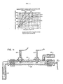
- Table 1 which lists conductivity vs. concentration, for several common solutions. In Figure 1 of the drawings, the variation of conductivity with temperature as well as concentration is shown (for NaOH solution).
- the dispenser 20 comprises (i) a collector 23 to retain a disposable container 200 of solid chemical 201 and direct the concentrated wash chemical solution into a solution conduit 25, (ii) a solution conduit 25 to carry concentrated chemical solution from the collector 23 into the washing machine (not shown), (iii) in the preferred embodiment, a pump 27 operatively connected to the solution conduit 25 to pump the concentrated chemical solution through the solution conduit 25 and into the washing machine (not shown), (iv) a conductivity sensing means 29 operatively connected to the solution conduit 25 to measure the conductivity of the concentrated chemical solution directed into the washing machine (not shown), (v) in the preferred embodiment, a temperature sensing means 30 ( Figure 4) operatively connected to the solution conduit 25 to measure the temperature of the concentrated chemical solution directed into the washing machine (not shown), (vi) a spray nozzle 31 ( Figure 3) operatively engaged within the collector 23 to direct a spray of water into the disposable container 200 which is retained by the collector 23 for dissolving the chemical within the disposable container 200, (vii)
- Figure 1 shows a species of dispenser 20 with a permanent container 200b with an upwardly disposed access port 250 for inserting additional chemical 201 into the container 200.
- the access port 250 is covered with an upwardly disposed cover 251 and the chemical in the container 200 is supported above the spray nozzle 31 by a support screen 253.
- the permanent container 200b may be refilled with wash chemical 201 thereby eliminating the need for multiple disposable containers 200a.
- the collector 23 may be equipped with a lower screen 39 below nozzle 31 to prevent the passage of solid undissolved chemical 201 into the solution conduit 25.
- the collector 23, disposable container 200, permanent container 200b, solution conduit 25, support screen 253 and lower screen 39 come in contact with the concentrated wash chemical solution and must therefore be made from a material which can withstand contact with the concentrated chemical solution without losing structural integrity.
- Materials which may be used include stainless steel, glass and thermoplastics such as polyethylene, polypropylene, polyvinyl chloride etc., with polypropylene being preferred because of its low cost and easy availability.
- the concentrated chemical solution may be gravity fed or pumped into the washing machine (not shown).
- the size of the pump is preferably about 1/30 h.p. to about 1/8 h.p. (25 to 93 J/s).
- the conductivity 29 and temperature 30 sensing means are stainless steel electrodes 29 and a thermistor 30 respectively and are located near the lower inner surface 26 of the solution conduit 25 in order to maintain contact with the concentrated chemical solution flowing through the solution conduit 25 at all times.
- the cell constant of the electrodes 29 is typically between 10 and 15/cm. with 11/cm. being the preferred cell constant.
- the spray nozzle 31 is positioned at the longitudinal center 24 ( Figure 3) of the collector 23 and the disposable container 200 or the permanent container 200b so that the water spray emitted by the spray nozzle 31 impinges upon substantially the entire lower surface area 202 of the chemical 201 stored in the container 200, thereby ensuring that all of the chemical 201 in the container 200 is utilized.
- the pressure regulating valve 35 preferably maintains the solvent pressure fed to the spray nozzle 31 at a constant within the range of about 10 to 40 p.s.i. (7000 to 28000 kg/m2), and most preferably in the range of about 15 to 25 p.s.i. (10,500 to 17,500 kg/m2).
- the functioning of the dispenser 20 is controlled by an electronic control mechanism 100 which is cooperatively connected to the feed line control valve 37, the pump 27, the conductivity sensing means 29, the temperature sensing means 30 and the washing machine (not shown) whereby in operation (i) the electronic control mechanism 100 receives an initiation signal from the washing machine (not shown) to begin dispensing, (ii) the electronic control mechanism 100 emits a control signal to the feed line control valve 37 along connection 137 to open the feed line 25 to water flow therethrough, (iii) the electronic control mechanism 100 emits a control signal to the pump 27 along connection 127 to begin pumping concentrated chemical solution, (iv) the conductivity sensing means 29 and temperature sensing means 30 emit measurement signals to the electronic control mechanism 100 along connections 129a, 129b and 130 respectively, (v) the electronic control mechanism 100 calculates the periodic amount of chemical 201 dispensed into the washing machine (not shown) based upon the known constant water flow rate, the period of time, the conductivity of the solution, and the temperature of the solution,
- the periodic amount of chemical 201 dispensed is preferably calculated about every 1/50 to 1/2 second, and most preferably about every 1/20 second.
- the electronic control mechanism 100 is capable of determining when the container 200 or 200b is empty and warning the operator. This is preferably done by monitoring the total amount of chemical 201 dispensed. When the total amount of chemical 201 dispensed does not meet or exceed a first predetermined minimum amount within a first preset time period the electronic control mechanism 100 warns the operator that the container 200 or 200b is empty.
- This first preset time period will vary dependent upon how quickly the predetermined amount of chemical 201 is typically dispensed and should normally be about 1-1/2 to 3 times this value. Generally speaking, this preset time period will be in the range of about 2 minutes to about 5 minutes.
- the electronic control panel 100 warns the operator that the container 200 or 200b is empty.
- the predetermined minimum amount of chemical 201 will vary dependent upon the particular chemical 201 but should be set well below the typical amount of that particular wash chemical 201 which is dispensed during the second predetermined minimum time period to avoid false readings.
- the second predetermined minimum time period is an arbitrarily set time period which should be long enough to ensure an accurate reading but not so long as to defeat the purpose of quickly warning the operator when the container 200 or 200b is empty.
- the preferred second predetermined minimum time period is generally in the range of about 10 to 30 seconds.
- Safety control switch 40 is operatively engaged with container 200 for sensing the relative movement of container 200 from complete sealing engagement with collector 23 for sensing when container 200 is jarred from a complete upright position over collector 23.
- Safety control switch 40 is operatively connected by conduction member 140a to a power source and by conduction member 140b to control valve 37.
- Control switch 40 is normally in an electrically open state preventing the passage of electricity from power source 2 to control valve 37, thereby preventing the passage of water through feed line 33.
- container 200 contacts safety switch 40 and depresses switch 40 creating an electrically closed switch 40 which thereby allows electrical power to flow from power source 2 to control valve 37 through electrical control panel 100 thereby allowing the flow of water through feed line 33.
- a plurality of dispensers 20 connected to a single electronic control mechanism 100 may be utilized, each for a different chemical 201 and each independently responsive to a control signal from the electronic control mechanism 100 for dispensing the desired amount of chemical 201 at the desired time during the wash cycle.
- Such multiple containers 200 or 200b may contain such different wash chemicals as detergent, bleach, softener, etc. wherein the detergent and bleach are dispensed during the wash cycle and the softener is dispensed during the rinse cycle.
- One or more metering pumps 50 may be included in the present invention for dispensing liquid chemicals of a known concentration thereby allowing chemicals which cannot be formed into solid or granular form to be dispensed into the washing machine (not shown) at the desired time. Operation of the metering pump 50 based upon a control signal from the electronic control mechanism 100 along connection 130 as to when to start and stop dispensing the liquid chemical solution.
- the preferred metering pump 50 is a peristaltic pump due to the caustic nature of many of the chemicals commonly used in the cleaning process.
- the electronic control panel was set to (i) receive temperature and conductivity measurements, (ii) calculate the periodic amount of detergent dispensed every 1/20 second, (iii) sum the periodic amounts to determine the total amount of detergent dispensed every 1/20 second, and (iv) stop dispensing when the total amount of detergent dispensed was equal or greater than the predetermined desired amount.
- the electrodes had a surface area of about 0.406 cm2 and were placed about 4.45 cm apart for a cell constant of 11 cm.
- the water pressure flowing into the dispenser was regulated at approximately 15 p.s.i. (10500 kg/m2).
- the percent deviation of actual amount of detergent dispensed from the predetermined amount desired is:
- Example II A second set of tests were conducted in accordance with the procedure disclosed in Example I except that instead of titrating a sample of the concentrated detergent formed, the container of detergent was weighed before and after dispensing to determine the amount of detergent dispensed. The resultant data is tabulated below.
- the margin of error is generally less than 10% indicating a margin of error within that allowable for efficient operation of the system and as indicated by the large variance in time of dispensing necessary to achieve substantially the same amount of detergent dispensed, the dispenser is a substantial improvement over simple timed dispensers.
Abstract
Description
- This invention relates generally to dispensers. More particularly,the invention relates to dispensers which control the quantity of chemical dispensed by measuring the conductivity of a solution of the chemical. Most particularly the invention relates to dispensers which dispense solid chemicals used in cleaning processes which control the quantity of chemical dispensed by measuring the conductivity of a solution of the chemical.
- The utilization of automatic dispensers to dispense chemicals used in cleaning processes is well known in the art. The automatic dispensers may generally be placed into two broad categories based upon their method of controlling the amount of chemical dispensed; (1) time controlled dispensers, and (2) conductivity measurement dispensers.
- Time controlled dispensers can only dispense solutions of known and/or constant concentration for if the concentration is unknown and variable different amounts of chemical will be dispensed during each cycle.
- One example of a widely utilized method of dispensing a solution used in cleaning processes wherein the concentration of the solution dispensed will be unknown and variable is described in U.S. Pat. No. 4,063,663 issued to Larson et al, which is expressly incorporated by reference herein. Larson discloses a dispenser wherein water is sprayed onto and dissolves the downward facing surface of a granular detergent for use in a washing machine.
- In attempts to control the quantity of chemical dispensed when the concentration of the solution is unknown or variable the relationship between solution concentration and temperature and conductivity of the solution can be utilized.
- For example, the effect of concentration and temperature upon the conductivity of sodium hydroxide solutions is presented in Table 1 and
Graph 1 respectively. Actual test data obtained from the dispensing system and the chemical dispensed will result in a generally observable and reproducible relationship between these three variables for that system. - Prior art devices control the quantity of chemical dispensed by measuring the conductivity of either (i) the wash water, or (ii) the concentrated chemical solution held in a reservoir with concentrated chemical solution being dispensed into the measured reservoir when the conductivity of the measured solution falls below a predetermined set value.
- It is preferable to measure the conductivity of the concentrated chemical solution because: (i) the wash water contains contaminants such as soil which can affect the conductivity of the wash water, (ii) there can be a large time lag between dispensing of the concentrated chemical solution and sensing of the change in conductivity of the wash water made by the additional chemical, and (iii) automatic dispensing devices are generally sold separately from the washing machine with which they are to be used and conductivity measurement of the wash water requires the implantation of electrodes into the washing machine requiring additional labor, added expense, and increasing the chance of failure.
- Measurement of the conductivity of concentrated chemical solution, used in the cleaning process, which is contained in a separate reservoir avoids the problems listed above but requires a separate reservoir to maintain concentrated chemical solution, increases the health hazards associated with the dispensing of chemicals used in the cleansing process as concentrated chemical solution is constantly present and may be spilled or splashed onto an operator, and requires an additional mechanism for time controlled dispensing of the concentrated chemical solution from the reservoir into the washing machine.
- Accordingly, a need exists for a compact dispenser which can dispense a desired quantity of a chemical in an aqueous chemical solution of an unknown and/or variable concentration in a safe, simple and accurate manner.
- According to this invention, there is provided a chemical dispenser for dispensing a predetermined quantity of a chemical solution of unknown or variable concentration to a utilization vehicle which comprises: a means for forming an aqueous solution of the chemical and an electronic control mechanism to be cooperatively connected, in use, to the utilization vehicle and to the solution forming means; characterized in that the electronic control mechanism includes means for receiving an initiating control signal to begin dispensing chemical solution into the utilization vehicle, means for emitting a control signal to the solution forming means to begin dispensing chemical solution into the utilization vehicle; and calculating means for periodically calculating the amount of chemical dispensed into the utilization vehicle by taking discrete measurements after predetermined time intervals, each calculation determining a periodic amount of chemical dispensed during the preceding time interval, said calculation means including means for measuring the conductivity of the aqueous solution of the chemical, said calculation means summing the periodic amounts to obtain a total amount of chemical dispensed and comparing the total amount to a predetermined amount of chemical to be dispensed and emitting a control signal to the solution forming means to stop dispensing chemical solution when a predetermined amount of chemical has been dispensed.
- This invention also provides a method for dispensing a predetermined quantity of a chemical in a solution of unknown or variable concentration into a utilization vehicle, including forming an aqueous solution of the chemical in a solution forming means and operating electronic control means to control operation of the solution forming means and supply of solution therefrom to the utilization vehicle, characterised in that the solution forming means and the electronic control means are comprised by a dispenser of any of the preceding claims and in that the dispenser is used in a procedure comprising the steps of:
- a) dispensing the chemical solution at a known constant flow rate into the utilization vehicle;
- (b) measuring the conductivity of the solution as the solution flows into the utilization vehicle;
- (c) calculating the amount of chemical dispensed with the vehicle by:
- (i) calculating a periodic amount of chemical dispensed into the utilization vehicle based on the known constant solution flow rate, the length of period and the conductivity of the solution, and
- (ii) summing the periodic amounts to obtain a total amount of chemical dispensed so far into the utilization vehicle;
- (d) periodically repeating steps (b) and (c); and
- (e) terminating flow of the solution into the utilization vehicle when the quantity of chemical dispensed into the utilization vehicle is equal to the predetermined amount of the chemical.
- In preferred practice, the dispenser of this invention includes means for initiating dispensing of a concentrated chemical solution at the appropriate time, (ii) means for forming a concentrated chemical solution, (iii) means for directing the concentrated chemical solution to its utilization point, (iv) means for measuring the conductivity and temperature of the concentrated chemical solution dispersed, (v) means for calculating the amount of chemical dispensed based upon the conductivity and temperature of the concentrated wash chemical solution dispensed, and (vi) means for terminating formation of the concentrated chemical solution when a predetermined amount of chemical has been dispensed.
- In particularly preferred practice: (i) a washing machine emits an electronic control signal to a spray control valve to open a solvent supply line to flow of solvent therethrough; (ii) the feed line control valve opens and solvent flows at a generally constant flow rate to a spray nozzle wherein the solvent is sprayed upon and dissolves the solid or granular chemicals retainably held above the spray nozzle; (iii) the concentrated chemical solution is immediately collected and dispensed into the washing machine; (iv) the conductivity and temperature of the concentrated chemical solution is measured before it enters the washing machine; (v) a microprocessor, based upon the known constant flow rate of solvent, the measured conductivity and temperature of the concentrated chemical solution, and the length of time since either the dispensing began or the last conductivity and temperature measurement was taken, calculates the periodic amount of chemical which has been dispensed; (vi) the microprocessor calculates the total amount of chemical dispensed by summing the periodic amounts; (vii) steps (iv) through (vi) are repeated until the predetermined amount of wash chemical has been dispensed; and (viii) the microprocessor emits a control signal to the spray control valve, closing the spray control valve to solvent flow therethrough, thereby terminating formation of concentrated chemical solution and preparing the system for another dispensing cycle.
- The present invention (i) may be utilized with concentrated chemical solutions of unknown and/or variable concentrations as it measures the quantity of chemical dispensed based directly upon the conductivity of the solution as it is coated, (ii) has virtually no lag time between dispensing and measurement as measurements are taken immediately following formation of the solution, (iii) is unaffected by contaminants found in the wash water as it measures conductivity prior to the concentrated solutions introduction into the wash water, (iv) does not require utilization of a separate reservoir for the concentrated solution as the concentrated solution is dispensed into the washing machine as it is formed, (v) does not retain concentrated solution as it is dispensed into the washing machine as it is formed, and (vi) does not require an additional mechanism for the time controlled dispensing of the concentrated solution.
- As the term is utilized herein, "utilization point" refers to the place wherein the chemical solution is utilized and performs its desired function and "utilization vehicle" refers to the apparatus wherein the chemical solution is utilized and performs its desired function.
- As the term is utilized herein, "periodic amount" refers to that amount of wash chemical dispensed during a single period of an arbitrary duration.
- For a better understanding of the invention and to show how the same can be carried into effect, reference will now be made, by way of example only, to the accompanying drawings, wherein:
- FIGURE 1 is a graph which depicts conductivity vs. concentration for sodium hydroxide solutions at several temperatures.
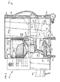
- FIGURE 2 is a front view of the dispenser of this invention for two chemicals.
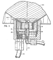
- FIGURE 3 is an expanded view, with portions thereof removed, of the collector, spray nozzle and portion of container with the access port.
- FIGURE 4 is an expanded view, with portions thereof removed, of the solution conduit containing the electrodes and the temperature sensor.
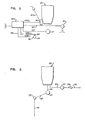
- FIGURE 5 is a schematic block diagram of the electrical flows.
- FIGURE 6 is a schematic block diagram of the fluid flows.
- Referring to Figure 2 there is generally disclosed a
dispenser 20 for dispensing a concentrated chemical solution to a utilization point. Thedispenser 20 is operatively connected with anelectronic control mechanism 100 for controlling the production of concentrated chemical solution # in the dispenser. - The
dispenser 20 will be further described in terms of dispensing a solid cast detergent into a washing machine (not shown) which is the preferred embodiment. However, it is emphasised that the dispenser works equally as well for the dispensing of any chemical to any utilization point so long as the solution's conductivity can be mathematically correlated to its concentration. In this connection, reference is made to Table 1 which lists conductivity vs. concentration, for several common solutions. In Figure 1 of the drawings, the variation of conductivity with temperature as well as concentration is shown (for NaOH solution).
- As best viewed in Fig. 2, the
dispenser 20 comprises (i) acollector 23 to retain adisposable container 200 ofsolid chemical 201 and direct the concentrated wash chemical solution into asolution conduit 25, (ii) a solution conduit 25 to carry concentrated chemical solution from thecollector 23 into the washing machine (not shown), (iii) in the preferred embodiment, apump 27 operatively connected to the solution conduit 25 to pump the concentrated chemical solution through thesolution conduit 25 and into the washing machine (not shown), (iv) a conductivity sensing means 29 operatively connected to the solution conduit 25 to measure the conductivity of the concentrated chemical solution directed into the washing machine (not shown), (v) in the preferred embodiment, a temperature sensing means 30 (Figure 4) operatively connected to the solution conduit 25 to measure the temperature of the concentrated chemical solution directed into the washing machine (not shown), (vi) a spray nozzle 31 (Figure 3) operatively engaged within thecollector 23 to direct a spray of water into thedisposable container 200 which is retained by thecollector 23 for dissolving the chemical within thedisposable container 200, (vii) asolvent feed line 33 connected to thespray nozzle 31 to supply thespray nozzle 31 with a pressurized source of water (not shown), (viii) apressure regulating valve 35 operatively connected with thefeed line 33 to maintain a constant flow rate of solvent to thespray nozzle 31, (ix) acontrol valve 37 operatively connected to thefeed line 33 to open and close thefeed line 33 to water flow therethrough in response to a control signal. - Strictly, Figure 1 shows a species of
dispenser 20 with apermanent container 200b with an upwardly disposedaccess port 250 for insertingadditional chemical 201 into thecontainer 200. Theaccess port 250 is covered with an upwardly disposedcover 251 and the chemical in thecontainer 200 is supported above thespray nozzle 31 by asupport screen 253. Thepermanent container 200b may be refilled withwash chemical 201 thereby eliminating the need for multiple disposable containers 200a. - The
collector 23 may be equipped with alower screen 39 belownozzle 31 to prevent the passage of solidundissolved chemical 201 into thesolution conduit 25. - The
collector 23,disposable container 200,permanent container 200b,solution conduit 25,support screen 253 andlower screen 39 come in contact with the concentrated wash chemical solution and must therefore be made from a material which can withstand contact with the concentrated chemical solution without losing structural integrity. Materials which may be used include stainless steel, glass and thermoplastics such as polyethylene, polypropylene, polyvinyl chloride etc., with polypropylene being preferred because of its low cost and easy availability. - The concentrated chemical solution may be gravity fed or pumped into the washing machine (not shown). The size of the pump is preferably about 1/30 h.p. to about 1/8 h.p. (25 to 93 J/s).
- Preferably, the
conductivity 29 andtemperature 30 sensing means arestainless steel electrodes 29 and athermistor 30 respectively and are located near the lowerinner surface 26 of the solution conduit 25 in order to maintain contact with the concentrated chemical solution flowing through the solution conduit 25 at all times. The cell constant of the electrodes 29 (distance between electrodes divided by cross-sectional area of solution between electrodes) is typically between 10 and 15/cm. with 11/cm. being the preferred cell constant. - Preferably, the
spray nozzle 31 is positioned at the longitudinal center 24 (Figure 3) of thecollector 23 and thedisposable container 200 or thepermanent container 200b so that the water spray emitted by thespray nozzle 31 impinges upon substantially the entirelower surface area 202 of thechemical 201 stored in thecontainer 200, thereby ensuring that all of thechemical 201 in thecontainer 200 is utilized. - The
pressure regulating valve 35 preferably maintains the solvent pressure fed to thespray nozzle 31 at a constant within the range of about 10 to 40 p.s.i. (7000 to 28000 kg/m²), and most preferably in the range of about 15 to 25 p.s.i. (10,500 to 17,500 kg/m²). - Referring to Figure 5, the functioning of the
dispenser 20 is controlled by anelectronic control mechanism 100 which is cooperatively connected to the feedline control valve 37, thepump 27, the conductivity sensing means 29, the temperature sensing means 30 and the washing machine (not shown) whereby in operation (i) theelectronic control mechanism 100 receives an initiation signal from the washing machine (not shown) to begin dispensing, (ii) theelectronic control mechanism 100 emits a control signal to the feedline control valve 37 alongconnection 137 to open thefeed line 25 to water flow therethrough, (iii) theelectronic control mechanism 100 emits a control signal to thepump 27 alongconnection 127 to begin pumping concentrated chemical solution, (iv) the conductivity sensing means 29 and temperature sensing means 30 emit measurement signals to theelectronic control mechanism 100 alongconnections 129a, 129b and 130 respectively, (v) theelectronic control mechanism 100 calculates the periodic amount ofchemical 201 dispensed into the washing machine (not shown) based upon the known constant water flow rate, the period of time, the conductivity of the solution, and the temperature of the solution, (vi) theelectronic control mechanism 100 calculates the total amount ofwash chemical 201 dispensed into the washing machine (not shown) by summing up all the periodic amounts ofchemical 201 dispensed, (vii) steps (iv) through (vi) inclusive are repeated until a predetermined amount ofwash chemical 201 has been dispensed, and (viii) theelectronic control mechanism 100 emits a signal to the feedline control valve 37 to stop the flow of solvent through thefeed line 33, thereby terminating the creation of concentrated chemical solution. - In order to reduce lag time and insure a more accurate calculation of the amount of
chemical 201 dispensed into the washing machine (not shown), the periodic amount ofchemical 201 dispensed is preferably calculated about every 1/50 to 1/2 second, and most preferably about every 1/20 second. - In the preferred embodiment the
electronic control mechanism 100 is capable of determining when thecontainer chemical 201 dispensed. When the total amount ofchemical 201 dispensed does not meet or exceed a first predetermined minimum amount within a first preset time period theelectronic control mechanism 100 warns the operator that thecontainer chemical 201 is typically dispensed and should normally be about 1-1/2 to 3 times this value. Generally speaking, this preset time period will be in the range of about 2 minutes to about 5 minutes. - Preferably, as an additional less lengthy check to determine if the
container chemical 201 dispensed does not meet a second predetermined minimum amount within a second preset minimum time period after dispensing of thechemical 201 is commenced, theelectronic control panel 100 warns the operator that thecontainer chemical 201 will vary dependent upon theparticular chemical 201 but should be set well below the typical amount of thatparticular wash chemical 201 which is dispensed during the second predetermined minimum time period to avoid false readings. The second predetermined minimum time period is an arbitrarily set time period which should be long enough to ensure an accurate reading but not so long as to defeat the purpose of quickly warning the operator when thecontainer -
Safety control switch 40 is operatively engaged withcontainer 200 for sensing the relative movement ofcontainer 200 from complete sealing engagement withcollector 23 for sensing whencontainer 200 is jarred from a complete upright position overcollector 23.Safety control switch 40 is operatively connected by conduction member 140a to a power source and byconduction member 140b to controlvalve 37.Control switch 40 is normally in an electrically open state preventing the passage of electricity frompower source 2 to controlvalve 37, thereby preventing the passage of water throughfeed line 33. Whencontainer 200 is placed withincollector 23,container 200contacts safety switch 40 and depresses switch 40 creating an electrically closedswitch 40 which thereby allows electrical power to flow frompower source 2 to controlvalve 37 throughelectrical control panel 100 thereby allowing the flow of water throughfeed line 33. - In a second embodiment a plurality of
dispensers 20 connected to a singleelectronic control mechanism 100 may be utilized, each for adifferent chemical 201 and each independently responsive to a control signal from theelectronic control mechanism 100 for dispensing the desired amount ofchemical 201 at the desired time during the wash cycle. Suchmultiple containers - One or more metering pumps 50 may be included in the present invention for dispensing liquid chemicals of a known concentration thereby allowing chemicals which cannot be formed into solid or granular form to be dispensed into the washing machine (not shown) at the desired time. Operation of the
metering pump 50 based upon a control signal from theelectronic control mechanism 100 alongconnection 130 as to when to start and stop dispensing the liquid chemical solution. Thepreferred metering pump 50 is a peristaltic pump due to the caustic nature of many of the chemicals commonly used in the cleaning process. - A container of "SOLID POWER" cast solid detergent whose composition is disclosed in copending U.S. patent application Serial No. 06/234,940, was placed in the dispenser of this invention. The electronic control panel was set to (i) receive temperature and conductivity measurements, (ii) calculate the periodic amount of detergent dispensed every 1/20 second, (iii) sum the periodic amounts to determine the total amount of detergent dispensed every 1/20 second, and (iv) stop dispensing when the total amount of detergent dispensed was equal or greater than the predetermined desired amount.
- The electrodes had a surface area of about 0.406 cm² and were placed about 4.45 cm apart for a cell constant of 11 cm. The water pressure flowing into the dispenser was regulated at approximately 15 p.s.i. (10500 kg/m²).
- The following Table summarizes the predetermined amount of detergent programmed into the electronic control panel, the time period that the dispenser operated, and the volume of concentrated detergent solution dispensed.

- A sample of the solution was then titrated using a 0.1 N HCl solution as the standard
The grams of detergent in the solution dispensed was calculated utilizing the folowing equation:
- U =
- volume of concentrated solution dispensed;
- S =
- volume of standard titrated to obtain the equivalence point (pH 8.3) of a 100 ml sample of concentrated chemical solution.

- C =
- a constant of 12.7 ml which is the volume of standard (0.1 N HCl) required to reach the equivalence point (pH 8.3) for 100 ml of a 1.0 gram wt-% "SOLID POWER" detergent solution (i.e. 12.7 ml of 0.1 N HCl standard equates to 1 gram of detergent); and
- 100
- converts the equation from percent to real numbers.
- The sample size, volume of standard used to reach the equivalence point and calculated grams of detergent in the total solution are summarized in the following Table.

- The percent deviation of actual amount of detergent dispensed from the predetermined amount desired is:
- (1) 6.2%
- (2) 6.2%
- (3) 2.5%
- (4) 3.3%,
- A second set of tests were conducted in accordance with the procedure disclosed in Example I except that instead of titrating a sample of the concentrated detergent formed, the container of detergent was weighed before and after dispensing to determine the amount of detergent dispensed. The resultant data is tabulated below.

- The margin of error is generally less than 10% indicating a margin of error within that allowable for efficient operation of the system and as indicated by the large variance in time of dispensing necessary to achieve substantially the same amount of detergent dispensed, the dispenser is a substantial improvement over simple timed dispensers.
Claims (19)
- A chemical dispenser (20) for dispensing a predetermined quantity of a chemical solution of unknown or variable concentration to a utilization vehicle which comprises: a means (20) for forming an aqueous solution of the chemical and an electronic control mechanism (100) to be cooperatively connected, in use, to the utilization vehicle and to the solution forming means (20); characterized in that the electronic control mechanism (100) includes means (27) for receiving an initiating control signal to begin dispensing chemical solution into the utilization vehicle, means for emitting a control signal to the solution forming means (20) to begin dispensing chemical solution into the utilization vehicle; calculating means for periodically calculating the amount of chemical dispensed into the utilization vehicle by taking discrete measurements after predetermined time intervals, each calculation determining a periodic amount of chemical dispensed during the preceding time interval, said calculation means including means (29) for measuring the conductivity of the aqueous solution of the chemical, said calculation means summing the periodic amounts to obtain a total amount of chemical dispensed and comparing the total amount to a predetermined amount of chemical to be dispensed; and means for emitting a control signal to the solution forming means to stop dispensing chemical solution when a predetermined amount of chemical has been dispensed.
- The dispenser of claim 1, which comprises a conductivity sensing means (29) cooperatively connected to a solution conduit (25) from said solution forming means (20) for sensing the conductivity of the chemical solution flowing through the conduit (25) and emitting a conductivity signal.
- The dispenser of claim 2 wherein:(a) the solution forming means (20) comprises:(i) a collector (23) for gathering the chemical solution;(ii) a spray forming nozzle (31) for directing a spray of solvent to dissolve the chemical;(iii) said solution conduit (25) connecting the collector (23) with the utilization vehicle for directing concentrated chemical solution from the collector (23) into the utilization vehicle;(iv) a solvent supply line (33) connecting the spray forming nozzle (31) with a source of solvent;(v) flow regulating means (35) cooperatively connected to the solvent supply line for maintaining a constant flow rate of solvent; and(vi) spray control means (37) cooperatively connected to the solvent supply line (33) for selectively controlling the flow of solvent to the nozzle (31) and being operative in response to receipt of a control signal to open and close the solvent supply line (33) to solvent flow.
- The dispenser of claim 3 wherein the electronic control mechanism is cooperatively connected to the utilization vehicle, the conductivity sensing means (29) and the spray control means (37) for:(i) receiving an initiating control signal emitted by the utilization vehicle to begin dispensing chemical solution into the utilization vehicle;(ii) emitting a control signal to the spray control means (37) to open the solvent supply line (33) to solvent flow therethrough;(iii) receiving the conductivity signal emitted by the conductivity sensing means (29);(iv) calculating a periodic amount of chemical dispensed into the utilization vehicle based upon the constant solvent flow rate, the length of the period and the conductivity of the chemical solution;(v) calculating the total amount of chemical dispensed into the utilization vehicle by summing the periodic amounts;(vi) repeating functions (iii) to (vi) until a predetermined amount of chemical has been dispensed into the utilization vehicle; and(vii) emitting a control signal to the spray control means (37) to close the solvent supply line (33) to solvent flow therethrough.
- The dispenser of claim 3 or 4 wherein:(a)(i) the collector (23) for gathering the chemical solution has:(A) an upper receiving means for retaining a container (200) having an upper chemical storage portion and a lower passage; and(B) a lower outlet port;(ii) the spray forming nozzle (31) is arranged to direct a spray of solvent into the upper storage portion of the said container (200), to dissolve that chemical carried immediately adjacent to the spray forming nozzle which passes in solution through the lower passage to the collector (23) and is immediately directed by the collector through the outlet port;(iii) the solution conduit (25) connects the outlet port with the utilization vehicle;(iv) the source of (33) solvent to which the solvent supply line is connected is pressurized; and(v) the flow regulating means (35) is pressure regulated.
- The dispenser of any one of claims 3 to 5 wherein additionally temperature sensing means (30) is cooperatively connected to the solution conduit (25) for sensing the temperature of the chemical solution and emitting a temperature signal; and calculation of the periodic amount of chemical dispensed into the utilization vehicle is additionally based upon the temperature of the chemical solution.
- The dispenser of claim 5 or 6 further comprising a screen (39) interposed between the spray-forming nozzle (31) and the outlet port for supporting undissolved solid chemical falling from storage.
- The dispenser of any one of claims 5 to 7, further comprising:(a) a solution pump (27) operatively connected with the solution conduit (25) for pumping concentrated chemical solution into the utilization vehicle and being operative in response to receipt of control signals to start and stop pumping; and(b) wherein the electronic control mechanism is cooperatively connected with the solution pump (27) for emitting control signals to the solution pump (i) to start pumping when the water supply line (33) is open to water flow, and (ii) to stop pumping when the water supply line (33) is closed to water flow.
- The dispenser of any one of claims 5 to 8, further comprising a liquid metering apparatus comprising:(a) a metering pump (50) for pumping the chemical solution into the utilization vehicle and being operative in response to receipt of a control signal to start and stop pumping;(b) a feed line connecting the metering pump (50) with a source of the chemical solution; and(c) a second conduit connecting the metering pump (50) with the utilization vehicle for directing the chemical solution from the metering pump into the utilization vehicle;wherein the electronic control mechanism (100) is cooperatively connected to the metering pump (50) for (i) receiving and initiating a control signal emitted by the utilization vehicle to begin dispensing the chemical solution thereinto, (ii) emitting a control signal to the metering pump (50) to start pumping, and (iii) emitting a time based control signal to the metering pump (50) to stop pumping.
- The dispenser of any one of claims 5 to 9, further comprising a safety control switch (40) responsive to movement of the container (200) to block spray immediately from the nozzle (31) whenever the container is tilted.
- The dispenser of any one of claims 5 to 10, wherein the electronic control mechanism (100) further comprises an empty container signalling means to warn when the total amount of chemical dispensed is no longer increasing.
- The dispenser of any one of claims 5 to 11, wherein the conductivity sensing means (29), and the temperature sensing means (30) if present, is/are located near the lower inner surface of a horizontal portion of the solution conduit (25) for ensuring that the sensing means continually contact(s) the chemical solution as it flows into the utilization vehicle.
- The dispenser of any one of claims 4 to 12, comprising a plurality of solution forming means (20), each being independently operative in response to receipt of a control signal to open and close the solvent supply line (25) associated therewith for supplying different chemicals to the utilization vehicle.
- The dispenser of claim 13 comprising a plurality of liquid metering apparatuses (50) each being independently operative in response to receipt of a control signal to start and stop pumping for supplying a different chemical solution.
- The dispenser of any preceding claim, which is operatively associated with a said utilization vehicle which is a washing machine.
- A method for dispensing a predetermined quantity of a chemical in a solution of unknown or variable concentration into a utilization vehicle, including forming an aqueous solution of the chemical in a solution forming means and operating electronic control means to control operation of the solution forming means and supply of solution therefrom to the utilization vehicle, characterised in that the solution forming means and the electronic control means are comprised by a dispenser of any of the preceding claims and in that the dispenser is used in a procedure comprising the steps of:a) dispensing the chemical solution at a known constant flow rate into the utilization vehicle;(b) measuring the conductivity of the solution as the solution flows into the utilization vehicle;(c) calculating the amount of chemical dispensed with the vehicle by:(i) calculating a periodic amount of chemical dispensed into the utilization vehicle based on the known constant solution flow rate, the length of period and the conductivity of the solution, and(ii) summing the periodic amounts to obtain a total amount of chemical dispensed so far into the utilization vehicle;(d) periodically repeating steps (b) and (c); and(e) terminating flow of the solution into the utilization vehicle when the quantity of chemical dispensed into the utilization vehicle is equal to the predetermined amount of the chemical.
- The method of claim 16, wherein the chemical is a wash chemical, the utilization vehicle being a washing machine.
- The method of claim 17, wherein the chemical is a said detergent composition.
- The method of any one of claims 16 to 18, wherein the periodic amount of chemical dispensed into the washing machine is calculated every 1/50 to 1/2 of a second.
Priority Applications (1)
| Application Number | Priority Date | Filing Date | Title |
|---|---|---|---|
| AT87300136T ATE80277T1 (en) | 1986-01-09 | 1987-01-08 | CHEMICAL SOLUTION DISPENSER AND METHOD FOR ITS USE. |
Applications Claiming Priority (2)
| Application Number | Priority Date | Filing Date | Title |
|---|---|---|---|
| US06/817,350 US4858449A (en) | 1986-01-09 | 1986-01-09 | Chemical solution dispenser apparatus and method of using |
| US817350 | 1986-01-09 |
Publications (3)
| Publication Number | Publication Date |
|---|---|
| EP0229038A2 EP0229038A2 (en) | 1987-07-15 |
| EP0229038A3 EP0229038A3 (en) | 1988-08-17 |
| EP0229038B1 true EP0229038B1 (en) | 1992-09-09 |
Family
ID=25222885
Family Applications (1)
| Application Number | Title | Priority Date | Filing Date |
|---|---|---|---|
| EP19870300136 Expired - Lifetime EP0229038B1 (en) | 1986-01-09 | 1987-01-08 | Chemical solution dispenser apparatus and method of use thereof |
Country Status (13)
| Country | Link |
|---|---|
| US (1) | US4858449A (en) |
| EP (1) | EP0229038B1 (en) |
| JP (1) | JP2601465B2 (en) |
| AT (1) | ATE80277T1 (en) |
| AU (1) | AU585111B2 (en) |
| CA (1) | CA1291006C (en) |
| DE (1) | DE3781560T2 (en) |
| DK (1) | DK168827B1 (en) |
| ES (1) | ES2033820T3 (en) |
| FI (1) | FI865376A (en) |
| MX (1) | MX162395A (en) |
| NO (1) | NO170456C (en) |
| NZ (1) | NZ218817A (en) |
Cited By (6)
| Publication number | Priority date | Publication date | Assignee | Title |
|---|---|---|---|---|
| WO1993017611A1 (en) * | 1992-03-12 | 1993-09-16 | Ecolab Inc. | Self-optimizing detergent controller |
| WO1996026115A2 (en) * | 1995-02-14 | 1996-08-29 | Ecolab Inc. | Solid chemical dispenser with movable nozzle |
| US5681400A (en) * | 1992-03-12 | 1997-10-28 | Ecolab Inc. | Self-optimizing detergent controller for controlling variable additive concentration level in a warewashing machine |
| WO1999023494A1 (en) * | 1997-11-03 | 1999-05-14 | Lang Apparatebau Gmbh | Diaphragm pump dosage monitoring device |
| US6241378B1 (en) | 1996-10-10 | 2001-06-05 | Henkel-Ecolab Gmbh & Co. Ohg | Dosing apparatus for detergent paste |
| WO2002058833A2 (en) * | 2001-01-24 | 2002-08-01 | Ecolab Gmbh & Co. Ohg | Method for producing, conveying and dosing a solution, and device for carrying out said method |
Families Citing this family (69)
| Publication number | Priority date | Publication date | Assignee | Title |
|---|---|---|---|---|
| IT1224695B (en) * | 1988-07-28 | 1990-10-18 | Merloni Termosanitari Spa | PERBORATE ACTIVATION DEVICE IN WASHING MACHINES |
| US5342587A (en) * | 1992-09-24 | 1994-08-30 | Sunburst Chemicals, Inc. | Detergent dispenser for use with solid cast detergent |
| US5478537A (en) * | 1992-09-24 | 1995-12-26 | Sunburst Chemicals, Inc. | Detergent dispenser for use with solid casting detergent |
| US5411716A (en) * | 1993-10-05 | 1995-05-02 | Ecolab Inc. | Solid detergent dispenser for floor scrubber machine |
| US5389344A (en) * | 1993-10-05 | 1995-02-14 | Ecolab Inc. | Variable concentration, solid chemical dispenser |
| US5461742A (en) * | 1994-02-16 | 1995-10-31 | Levi Strauss & Co. | Mist treatment of garments |
| US5494644A (en) * | 1994-12-06 | 1996-02-27 | Ecolab Inc. | Multiple product dispensing system including dispenser for forming use solution from solid chemical compositions |
| US5746238A (en) * | 1995-03-31 | 1998-05-05 | Ecolab, Inc. | Liquid chemical dilution and dosing system |
| JPH0933538A (en) * | 1995-07-19 | 1997-02-07 | Toa Medical Electronics Co Ltd | Method and unit for preparing reagent |
| US5826749A (en) * | 1996-02-22 | 1998-10-27 | Nova Controls | Multiplexed system for dispensing multiple chemicals to multiple destinations |
| US5846499A (en) * | 1996-02-27 | 1998-12-08 | Sunburst Chemicals, Inc. | Air induction bowl for use with a detergent dispenser |
| US5782109A (en) * | 1996-05-06 | 1998-07-21 | Ecolab Inc. | Dispenser |
| US6217892B1 (en) | 1997-10-24 | 2001-04-17 | Joseph A. King | Water treatment composition |
| US6156715A (en) | 1997-01-13 | 2000-12-05 | Ecolab Inc. | Stable solid block metal protecting warewashing detergent composition |
| US6150324A (en) | 1997-01-13 | 2000-11-21 | Ecolab, Inc. | Alkaline detergent containing mixed organic and inorganic sequestrants resulting in improved soil removal |
| US6258765B1 (en) | 1997-01-13 | 2001-07-10 | Ecolab Inc. | Binding agent for solid block functional material |
| US6177392B1 (en) | 1997-01-13 | 2001-01-23 | Ecolab Inc. | Stable solid block detergent composition |
| US5928608A (en) * | 1998-01-08 | 1999-07-27 | Arch Chemicals Inc. | Intermittant spray system for water treatment |
| NZ506738A (en) * | 1998-03-18 | 2003-06-30 | Ecolab Inc | Solid block enzymatic cleaning with electrolytic control for clean-in-place systems |
| US6240953B1 (en) | 1998-04-13 | 2001-06-05 | Sunburst Chemicals, Inc. | Multiple cleaning chemical dispenser |
| US6423280B1 (en) | 1998-10-29 | 2002-07-23 | Ecolab Inc. | Hydraulic control of detergent concentration in an automatic warewashing machine |
| DE19852164A1 (en) * | 1998-11-12 | 2000-05-25 | Lang Apparatebau Gmbh | Method and device for detecting the quantity of a product dissolved in a solution stream |
| US6463611B1 (en) | 1999-04-02 | 2002-10-15 | Ecolab, Inc. | Apparatus for dispensing incompatible chemicals to a common utilization point |
| US6377868B1 (en) * | 1999-10-28 | 2002-04-23 | Ecolab Inc. | Data processing system for managing chemical product usage |
| US20050164902A1 (en) * | 2003-10-24 | 2005-07-28 | Ecolab Inc. | Stable compositions of spores, bacteria, and/or fungi |
| US7795199B2 (en) | 2000-06-29 | 2010-09-14 | Ecolab Inc. | Stable antimicrobial compositions including spore, bacteria, fungi, and/or enzyme |
| US7569532B2 (en) | 2000-06-29 | 2009-08-04 | Ecolab Inc. | Stable liquid enzyme compositions |
| US6624132B1 (en) * | 2000-06-29 | 2003-09-23 | Ecolab Inc. | Stable liquid enzyme compositions with enhanced activity |
| US6638902B2 (en) | 2001-02-01 | 2003-10-28 | Ecolab Inc. | Stable solid enzyme compositions and methods employing them |
| US6632291B2 (en) | 2001-03-23 | 2003-10-14 | Ecolab Inc. | Methods and compositions for cleaning, rinsing, and antimicrobial treatment of medical equipment |
| US6418958B1 (en) | 2001-04-02 | 2002-07-16 | Betzdearborn, Inc. | Dual solid chemical feed system |
| US6763860B2 (en) | 2001-07-10 | 2004-07-20 | Ecolab, Inc. | Flow-based chemical dispense system |
| US6637478B2 (en) | 2001-07-10 | 2003-10-28 | Ecolab Inc. | Fill station for a liquid dispensing system |
| US7292914B2 (en) | 2001-07-10 | 2007-11-06 | Ecolab Inc. | Remote access to chemical dispense system |
| US20040083771A1 (en) * | 2002-11-04 | 2004-05-06 | Simmons Mark S. | Dry chemical dispensing system |
| US20040230339A1 (en) * | 2003-05-12 | 2004-11-18 | Bryan Maser | Methods of managing based on measurements of actual use of product |
| US7201290B2 (en) * | 2003-05-12 | 2007-04-10 | Ecolab Inc. | Method and apparatus for mass based dispensing |
| US20040226959A1 (en) | 2003-05-12 | 2004-11-18 | Mehus Richard J. | Methods of dispensing |
| WO2006000237A1 (en) | 2004-06-23 | 2006-01-05 | Ecolab Inc. | Method for multiple dosage of liquid products, dosing appartus and dosing system |
| DE602005027271D1 (en) * | 2004-10-18 | 2011-05-12 | Ecolab Inc | Method and device for dispensing a liquid |
| US7803321B2 (en) * | 2005-03-18 | 2010-09-28 | Ecolab Inc. | Formulating chemical solutions based on volumetric and weight based control measurements |
| WO2008016683A1 (en) * | 2006-08-01 | 2008-02-07 | The Procter & Gamble Company | Receiving apparatus |
| US8277745B2 (en) | 2007-05-02 | 2012-10-02 | Ecolab Inc. | Interchangeable load cell assemblies |
| JP2009136765A (en) * | 2007-12-06 | 2009-06-25 | Tominaga Oil Pump Mfg Co Ltd | Apparatus for subdividing asphalt anti-adhesive agent |
| US7694589B2 (en) | 2007-12-12 | 2010-04-13 | Ecolab Inc. | Low and empty product detection using load cell and load cell bracket |
| US8266748B2 (en) * | 2008-07-01 | 2012-09-18 | Whirlpool Corporation | Apparatus and method for controlling bulk dispensing of wash aid by sensing wash aid concentration |
| US8397328B2 (en) | 2008-07-01 | 2013-03-19 | Whirlpool Corporation | Apparatus and method for controlling concentration of wash aid in wash liquid |
| US8388695B2 (en) * | 2008-07-01 | 2013-03-05 | Whirlpool Corporation | Apparatus and method for controlling laundering cycle by sensing wash aid concentration |
| US20100025338A1 (en) * | 2008-08-01 | 2010-02-04 | Delaware Capital Formation, Inc. | Chemical additive apparatus and methods |
| US7964548B2 (en) * | 2009-01-20 | 2011-06-21 | Ecolab Usa Inc. | Stable aqueous antimicrobial enzyme compositions |
| US7723281B1 (en) | 2009-01-20 | 2010-05-25 | Ecolab Inc. | Stable aqueous antimicrobial enzyme compositions comprising a tertiary amine antimicrobial |
| USRE48951E1 (en) | 2015-08-05 | 2022-03-01 | Ecolab Usa Inc. | Hand hygiene compliance monitoring |
| US9102509B2 (en) | 2009-09-25 | 2015-08-11 | Ecolab Inc. | Make-up dispense in a mass based dispensing system |
| US9051163B2 (en) | 2009-10-06 | 2015-06-09 | Ecolab Inc. | Automatic calibration of chemical product dispense systems |
| US8511512B2 (en) | 2010-01-07 | 2013-08-20 | Ecolab Usa Inc. | Impact load protection for mass-based product dispensers |
| US8852442B2 (en) * | 2010-03-08 | 2014-10-07 | Delaware Capital Formation, Inc. | Solid chemical dissolver and methods |
| US8398850B2 (en) | 2010-09-17 | 2013-03-19 | Evapco, Inc. | Water treatment feeder device and a water treatment feeder system |
| EP2777473B1 (en) * | 2010-12-20 | 2016-09-28 | Ecolab Inc. | A dispensing system for dispensing a solid substance being conductive in solution and an according method |
| US9022642B2 (en) | 2011-04-28 | 2015-05-05 | Hubert Ray Broome | Dissolution generator, method of dissolving powder, and mixing system |
| US10544340B2 (en) | 2011-10-20 | 2020-01-28 | Henderson Products, Inc. | Brine generation system |
| US10766010B2 (en) | 2011-10-20 | 2020-09-08 | Henderson Products, Inc. | High throughput brine generating system |
| US20130294978A1 (en) | 2012-05-03 | 2013-11-07 | Reynato Mariano | Chemical dissolving dispenser |
| US9399198B2 (en) | 2012-10-12 | 2016-07-26 | Sunburst Chemicals, Inc. | Venturi ejector for a chemical dispenser |
| US8944286B2 (en) | 2012-11-27 | 2015-02-03 | Ecolab Usa Inc. | Mass-based dispensing using optical displacement measurement |
| US9989941B2 (en) | 2014-12-02 | 2018-06-05 | Ecolab Usa Inc. | Solid chemistry supply management system |
| BR112019018376B1 (en) | 2017-03-07 | 2024-02-20 | Ecolab Usa Inc | DEVICE, AND, DISPENSER SIGNALING MODULE |
| US11058999B1 (en) | 2017-07-10 | 2021-07-13 | Hubert R. Broome | Rapid dissolution generator system and method for producing same |
| US10529219B2 (en) | 2017-11-10 | 2020-01-07 | Ecolab Usa Inc. | Hand hygiene compliance monitoring |
| EP3900307A1 (en) | 2018-12-20 | 2021-10-27 | Ecolab USA, Inc. | Adaptive route, bi-directional network communication |
Family Cites Families (41)
| Publication number | Priority date | Publication date | Assignee | Title |
|---|---|---|---|---|
| US2382164A (en) * | 1945-08-14 | Detergent briquette | ||
| US2382163A (en) * | 1945-08-14 | Detergent briquette | ||
| US2382165A (en) * | 1945-08-14 | Detergent briquette | ||
| US1932070A (en) * | 1931-02-28 | 1933-10-24 | Economics Lab | Solution tank |
| US1975749A (en) * | 1931-08-31 | 1934-10-02 | Charles A Lang | Solution tank |
| US1945351A (en) * | 1932-02-12 | 1934-01-30 | Foster D Snell Inc | Soap dispenser |
| US2138943A (en) * | 1937-06-23 | 1938-12-06 | Raymond E Marquis | Alkali solution dispenser for dish washing machines |
| US2120807A (en) * | 1937-06-29 | 1938-06-14 | Joseph Parisi | Device for soaping flowing water |
| US2370609A (en) * | 1941-04-28 | 1945-02-27 | Economics Lab | Concentration cell and temperature compensator |
| US2308612A (en) * | 1941-07-23 | 1943-01-19 | Milk Plant Specialties Corp | Dissolving apparatus |
| US2371720A (en) * | 1943-08-09 | 1945-03-20 | Turco Products Inc | Admixing and dispensing method and device |
| US2388791A (en) * | 1943-08-12 | 1945-11-13 | William H Maxwell | Hair curler |
| US2412819A (en) * | 1945-07-21 | 1946-12-17 | Mathieson Alkali Works Inc | Detergent briquette |
| US2614574A (en) * | 1948-04-12 | 1952-10-21 | Allied Chem & Dye Corp | Chemical feeder and method of feeding |
| US2738323A (en) * | 1952-07-10 | 1956-03-13 | Olin Mathieson | Chemical feeder |
| US2820701A (en) * | 1954-06-28 | 1958-01-21 | Donald J Leslie | Apparatus for chlorination |
| FR1292039A (en) * | 1961-06-12 | 1962-04-27 | Laundering cycle control | |
| US3070316A (en) * | 1961-06-16 | 1962-12-25 | Miville Edouard | Soap and water mixing valve |
| US3220607A (en) * | 1964-05-13 | 1965-11-30 | Gen Electric | Conditioning material dispenser for washing machines |
| US3383178A (en) * | 1964-12-02 | 1968-05-14 | Pittsburgh Plate Glass Co | Chemical dissolver |
| US3253741A (en) * | 1965-01-21 | 1966-05-31 | Wesley Mfg Co | Car wash device |
| US3307744A (en) * | 1965-10-18 | 1967-03-07 | Pennsalt Chemicals Corp | Method and apparatus for automatic control of cleaning solution concentrations in vehicle washing system |
| US3319637A (en) * | 1966-07-11 | 1967-05-16 | Intercontinental Chem Corp | Means for monitoring and maintaining concentration of depletable work solutions |
| US3595438A (en) * | 1969-01-06 | 1971-07-27 | Economics Lab | Automatic detergent dispenser system |
| US3592538A (en) * | 1969-12-17 | 1971-07-13 | Ricoh Kk | Photographic copying apparatus |
| US3727889A (en) * | 1970-05-21 | 1973-04-17 | Chapman Chem Co | Mixing method and apparatus |
| US3680070A (en) * | 1970-05-25 | 1972-07-25 | Economics Lab | Electronic control means for dispensing apparatus |
| US3653543A (en) * | 1970-07-13 | 1972-04-04 | Fritz K Preikschat | Proportional bin level and flow control system |
| US3850344A (en) * | 1972-07-28 | 1974-11-26 | Calgon Corp | Inverted drum feeder for powdered detergent |
| US3804297A (en) * | 1973-06-08 | 1974-04-16 | Jetronic Ind Inc | Liquid chemical mixing and delivery system |
| US4026673A (en) * | 1975-05-29 | 1977-05-31 | Leonard Russo | Apparatus for dissolving and dispensing fertilizer to either of two water streams of different pressure |
| US4020865A (en) * | 1975-10-03 | 1977-05-03 | Economics Laboratory, Inc. | Remote powder detergent dispenser |
| US4063663A (en) * | 1975-12-15 | 1977-12-20 | Economics Laboratory, Inc. | Powdered detergent dispenser |
| US4076146A (en) * | 1976-03-03 | 1978-02-28 | Gibson Chemicals International Pty. Limited | Dishwashers and detergent dispensers |
| US4426362A (en) * | 1978-12-05 | 1984-01-17 | Economics Laboratory, Inc. | Solid block detergent dispenser |
| US4462511A (en) * | 1980-09-15 | 1984-07-31 | Viking Injector Company | Dissolving and dispensing apparatus |
| GB2092902B (en) * | 1981-02-13 | 1985-01-03 | Berelson Rudolf | Spray mixing apparatus |
| US4357953A (en) * | 1981-02-26 | 1982-11-09 | Sterling Drug Inc. | Apparatus for slurrying powdered solids |
| DE3118973A1 (en) * | 1981-05-13 | 1982-12-02 | Lang Apparatebau GmbH, 8227 Siegsdorf | "DOSING METHOD FOR SUPPLYING A WASHING MACHINE WITH DETERGENT CONCENTRATE AND DEVICE FOR CARRYING OUT THE METHOD" |
| JPS59138801A (en) * | 1983-01-29 | 1984-08-09 | 日機装株式会社 | Control system of injection of chemical |
| US4687121A (en) * | 1986-01-09 | 1987-08-18 | Ecolab Inc. | Solid block chemical dispenser for cleaning systems |
-
1986
- 1986-01-09 US US06/817,350 patent/US4858449A/en not_active Expired - Lifetime
- 1986-12-31 FI FI865376A patent/FI865376A/en not_active IP Right Cessation
-
1987
- 1987-01-02 AU AU67104/87A patent/AU585111B2/en not_active Expired
- 1987-01-06 DK DK005687A patent/DK168827B1/en not_active IP Right Cessation
- 1987-01-06 NZ NZ21881787A patent/NZ218817A/en unknown
- 1987-01-07 NO NO870063A patent/NO170456C/en unknown
- 1987-01-08 ES ES87300136T patent/ES2033820T3/en not_active Expired - Lifetime
- 1987-01-08 EP EP19870300136 patent/EP0229038B1/en not_active Expired - Lifetime
- 1987-01-08 AT AT87300136T patent/ATE80277T1/en not_active IP Right Cessation
- 1987-01-08 DE DE19873781560 patent/DE3781560T2/en not_active Expired - Lifetime
- 1987-01-09 CA CA 527065 patent/CA1291006C/en not_active Expired - Fee Related
- 1987-01-09 MX MX4905A patent/MX162395A/en unknown
- 1987-01-09 JP JP310587A patent/JP2601465B2/en not_active Expired - Lifetime
Cited By (12)
| Publication number | Priority date | Publication date | Assignee | Title |
|---|---|---|---|---|
| WO1993017611A1 (en) * | 1992-03-12 | 1993-09-16 | Ecolab Inc. | Self-optimizing detergent controller |
| US5404893A (en) * | 1992-03-12 | 1995-04-11 | Ecolab Inc. | Self-optimizing detergent controller |
| AU670553B2 (en) * | 1992-03-12 | 1996-07-25 | Ecolab Inc. | Self-optimizing detergent controller |
| US5556478A (en) * | 1992-03-12 | 1996-09-17 | Ecolab Inc. | Self-optimizing detergent controller for minimizing detergent set-point overshoot |
| US5681400A (en) * | 1992-03-12 | 1997-10-28 | Ecolab Inc. | Self-optimizing detergent controller for controlling variable additive concentration level in a warewashing machine |
| WO1996026115A2 (en) * | 1995-02-14 | 1996-08-29 | Ecolab Inc. | Solid chemical dispenser with movable nozzle |
| AU686822B2 (en) * | 1995-02-14 | 1998-02-12 | Ecolab Inc. | Solid chemical dispenser with movable nozzle |
| US6241378B1 (en) | 1996-10-10 | 2001-06-05 | Henkel-Ecolab Gmbh & Co. Ohg | Dosing apparatus for detergent paste |
| WO1999023494A1 (en) * | 1997-11-03 | 1999-05-14 | Lang Apparatebau Gmbh | Diaphragm pump dosage monitoring device |
| DE19748449C1 (en) * | 1997-11-03 | 1999-06-24 | Lang Apparatebau Gmbh | Device for monitoring the metering of a diaphragm pump |
| WO2002058833A2 (en) * | 2001-01-24 | 2002-08-01 | Ecolab Gmbh & Co. Ohg | Method for producing, conveying and dosing a solution, and device for carrying out said method |
| DE10103091A1 (en) * | 2001-01-24 | 2002-08-01 | Ecolab Gmbh & Co Ohg | Process for producing, conveying and metering a solution and device for carrying out the process |
Also Published As
| Publication number | Publication date |
|---|---|
| CA1291006C (en) | 1991-10-22 |
| ES2033820T3 (en) | 1993-04-01 |
| US4858449A (en) | 1989-08-22 |
| JP2601465B2 (en) | 1997-04-16 |
| NO170456B (en) | 1992-07-13 |
| DK5687D0 (en) | 1987-01-06 |
| FI865376A0 (en) | 1986-12-31 |
| ATE80277T1 (en) | 1992-09-15 |
| JPS62225239A (en) | 1987-10-03 |
| EP0229038A3 (en) | 1988-08-17 |
| DE3781560T2 (en) | 1993-01-07 |
| DK5687A (en) | 1987-07-10 |
| DK168827B1 (en) | 1994-06-20 |
| AU6710487A (en) | 1987-07-16 |
| AU585111B2 (en) | 1989-06-08 |
| DE3781560D1 (en) | 1992-10-15 |
| NO170456C (en) | 1992-10-21 |
| NO870063L (en) | 1987-07-10 |
| MX162395A (en) | 1991-05-06 |
| NO870063D0 (en) | 1987-01-07 |
| EP0229038A2 (en) | 1987-07-15 |
| NZ218817A (en) | 1989-08-29 |
| FI865376A (en) | 1987-07-10 |
Similar Documents
| Publication | Publication Date | Title |
|---|---|---|
| EP0229038B1 (en) | Chemical solution dispenser apparatus and method of use thereof | |
| US4964185A (en) | Chemical solution dispenser apparatus and method of using | |
| EP0700264B1 (en) | Low product alarm for solid products | |
| US10065156B2 (en) | Method and apparatus for dispensing solid product | |
| US4976137A (en) | Chemical mixing and dispensing system | |
| US5137694A (en) | Industrial solid detergent dispenser and cleaning system | |
| US6152327A (en) | Dispensing method and device | |
| US8950271B2 (en) | Material dispensing system and method with capacitance sensor assembly | |
| EP1793725B1 (en) | Solid detergent dispenser and use of such dispenser | |
| US6095370A (en) | Encapsulated liquid dispensing device and method | |
| US9290884B2 (en) | Dosing apparatus and method for dosing a composition | |
| KR20100111694A (en) | Material delivery systems and methods | |
| EP0118195A2 (en) | Measurement and control of viscosity | |
| EP0864684B1 (en) | System, method and control device for dosing detergent | |
| US3224638A (en) | Adjustable liquid metering device | |
| CN110685120A (en) | Automatic feeding control method of clothes treating agent of clothes treating equipment | |
| US20060162809A1 (en) | Apparatus and method for dispensing products | |
| CN106290343A (en) | Total surplus line oxide real-time detection apparatus and detection method | |
| CS263207B1 (en) | Device for measuring and indication of dangerous concentration hcl in air | |
| CS198553B1 (en) | Liquid reagent dosing apparatus |
Legal Events
| Date | Code | Title | Description |
|---|---|---|---|
| PUAI | Public reference made under article 153(3) epc to a published international application that has entered the european phase |
Free format text: ORIGINAL CODE: 0009012 |
|
| AK | Designated contracting states |
Kind code of ref document: A2 Designated state(s): AT BE CH DE ES FR GB IT LI LU NL SE |
|
| PUAL | Search report despatched |
Free format text: ORIGINAL CODE: 0009013 |
|
| AK | Designated contracting states |
Kind code of ref document: A3 Designated state(s): AT BE CH DE ES FR GB IT LI LU NL SE |
|
| 17P | Request for examination filed |
Effective date: 19881221 |
|
| 17Q | First examination report despatched |
Effective date: 19890612 |
|
| ITTA | It: last paid annual fee | ||
| GRAA | (expected) grant |
Free format text: ORIGINAL CODE: 0009210 |
|
| ITF | It: translation for a ep patent filed |
Owner name: BARZANO' E ZANARDO MILANO S.P.A. |
|
| AK | Designated contracting states |
Kind code of ref document: B1 Designated state(s): AT BE CH DE ES FR GB IT LI LU NL SE |
|
| REF | Corresponds to: |
Ref document number: 80277 Country of ref document: AT Date of ref document: 19920915 Kind code of ref document: T |
|
| REF | Corresponds to: |
Ref document number: 3781560 Country of ref document: DE Date of ref document: 19921015 |
|
| ET | Fr: translation filed | ||
| REG | Reference to a national code |
Ref country code: ES Ref legal event code: FG2A Ref document number: 2033820 Country of ref document: ES Kind code of ref document: T3 |
|
| PLBE | No opposition filed within time limit |
Free format text: ORIGINAL CODE: 0009261 |
|
| STAA | Information on the status of an ep patent application or granted ep patent |
Free format text: STATUS: NO OPPOSITION FILED WITHIN TIME LIMIT |
|
| 26N | No opposition filed | ||
| EPTA | Lu: last paid annual fee | ||
| PGFP | Annual fee paid to national office [announced via postgrant information from national office to epo] |
Ref country code: CH Payment date: 19941215 Year of fee payment: 9 |
|
| PGFP | Annual fee paid to national office [announced via postgrant information from national office to epo] |
Ref country code: ES Payment date: 19950119 Year of fee payment: 9 |
|
| EAL | Se: european patent in force in sweden |
Ref document number: 87300136.6 |
|
| PG25 | Lapsed in a contracting state [announced via postgrant information from national office to epo] |
Ref country code: ES Free format text: LAPSE BECAUSE OF NON-PAYMENT OF DUE FEES Effective date: 19960109 |
|
| PG25 | Lapsed in a contracting state [announced via postgrant information from national office to epo] |
Ref country code: CH Effective date: 19960131 Ref country code: LI Effective date: 19960131 |
|
| REG | Reference to a national code |
Ref country code: CH Ref legal event code: PL |
|
| PGFP | Annual fee paid to national office [announced via postgrant information from national office to epo] |
Ref country code: LU Payment date: 19980109 Year of fee payment: 12 |
|
| PG25 | Lapsed in a contracting state [announced via postgrant information from national office to epo] |
Ref country code: LU Free format text: LAPSE BECAUSE OF NON-PAYMENT OF DUE FEES Effective date: 19990108 |
|
| REG | Reference to a national code |
Ref country code: ES Ref legal event code: FD2A Effective date: 20010910 |
|
| REG | Reference to a national code |
Ref country code: GB Ref legal event code: IF02 |
|
| PGFP | Annual fee paid to national office [announced via postgrant information from national office to epo] |
Ref country code: GB Payment date: 20051209 Year of fee payment: 20 |
|
| PGFP | Annual fee paid to national office [announced via postgrant information from national office to epo] |
Ref country code: NL Payment date: 20051212 Year of fee payment: 20 Ref country code: AT Payment date: 20051212 Year of fee payment: 20 |
|
| PGFP | Annual fee paid to national office [announced via postgrant information from national office to epo] |
Ref country code: FR Payment date: 20060104 Year of fee payment: 20 |
|
| PGFP | Annual fee paid to national office [announced via postgrant information from national office to epo] |
Ref country code: SE Payment date: 20060109 Year of fee payment: 20 |
|
| PGFP | Annual fee paid to national office [announced via postgrant information from national office to epo] |
Ref country code: BE Payment date: 20060127 Year of fee payment: 20 |
|
| PGFP | Annual fee paid to national office [announced via postgrant information from national office to epo] |
Ref country code: IT Payment date: 20060131 Year of fee payment: 20 Ref country code: DE Payment date: 20060131 Year of fee payment: 20 |
|
| PG25 | Lapsed in a contracting state [announced via postgrant information from national office to epo] |
Ref country code: GB Free format text: LAPSE BECAUSE OF EXPIRATION OF PROTECTION Effective date: 20070107 |
|
| PG25 | Lapsed in a contracting state [announced via postgrant information from national office to epo] |
Ref country code: NL Free format text: LAPSE BECAUSE OF EXPIRATION OF PROTECTION Effective date: 20070108 |
|
| REG | Reference to a national code |
Ref country code: GB Ref legal event code: PE20 |
|
| NLV7 | Nl: ceased due to reaching the maximum lifetime of a patent |
Effective date: 20070108 |
|
| EUG | Se: european patent has lapsed | ||
| BE20 | Be: patent expired |
Owner name: *ECOLAB INC. Effective date: 20070108 |