EP0197963B1 - Apparatus for installing connectors on flat cable having automatic connector delivery system and selective orientation feature for the connectors - Google Patents
Apparatus for installing connectors on flat cable having automatic connector delivery system and selective orientation feature for the connectors Download PDFInfo
- Publication number
- EP0197963B1 EP0197963B1 EP85904727A EP85904727A EP0197963B1 EP 0197963 B1 EP0197963 B1 EP 0197963B1 EP 85904727 A EP85904727 A EP 85904727A EP 85904727 A EP85904727 A EP 85904727A EP 0197963 B1 EP0197963 B1 EP 0197963B1
- Authority
- EP
- European Patent Office
- Prior art keywords
- housing
- turntable
- belt
- connectors
- zone
- Prior art date
- Legal status (The legal status is an assumption and is not a legal conclusion. Google has not performed a legal analysis and makes no representation as to the accuracy of the status listed.)
- Expired
Links
Images


Classifications
-
- B—PERFORMING OPERATIONS; TRANSPORTING
- B23—MACHINE TOOLS; METAL-WORKING NOT OTHERWISE PROVIDED FOR
- B23P—METAL-WORKING NOT OTHERWISE PROVIDED FOR; COMBINED OPERATIONS; UNIVERSAL MACHINE TOOLS
- B23P19/00—Machines for simply fitting together or separating metal parts or objects, or metal and non-metal parts, whether or not involving some deformation; Tools or devices therefor so far as not provided for in other classes
- B23P19/001—Article feeders for assembling machines
- B23P19/002—Article feeders for assembling machines orientating the articles
-
- B—PERFORMING OPERATIONS; TRANSPORTING
- B23—MACHINE TOOLS; METAL-WORKING NOT OTHERWISE PROVIDED FOR
- B23P—METAL-WORKING NOT OTHERWISE PROVIDED FOR; COMBINED OPERATIONS; UNIVERSAL MACHINE TOOLS
- B23P19/00—Machines for simply fitting together or separating metal parts or objects, or metal and non-metal parts, whether or not involving some deformation; Tools or devices therefor so far as not provided for in other classes
- B23P19/001—Article feeders for assembling machines
-
- H—ELECTRICITY
- H01—ELECTRIC ELEMENTS
- H01R—ELECTRICALLY-CONDUCTIVE CONNECTIONS; STRUCTURAL ASSOCIATIONS OF A PLURALITY OF MUTUALLY-INSULATED ELECTRICAL CONNECTING ELEMENTS; COUPLING DEVICES; CURRENT COLLECTORS
- H01R43/00—Apparatus or processes specially adapted for manufacturing, assembling, maintaining, or repairing of line connectors or current collectors or for joining electric conductors
- H01R43/01—Apparatus or processes specially adapted for manufacturing, assembling, maintaining, or repairing of line connectors or current collectors or for joining electric conductors for connecting unstripped conductors to contact members having insulation cutting edges
-
- Y—GENERAL TAGGING OF NEW TECHNOLOGICAL DEVELOPMENTS; GENERAL TAGGING OF CROSS-SECTIONAL TECHNOLOGIES SPANNING OVER SEVERAL SECTIONS OF THE IPC; TECHNICAL SUBJECTS COVERED BY FORMER USPC CROSS-REFERENCE ART COLLECTIONS [XRACs] AND DIGESTS
- Y10—TECHNICAL SUBJECTS COVERED BY FORMER USPC
- Y10T—TECHNICAL SUBJECTS COVERED BY FORMER US CLASSIFICATION
- Y10T29/00—Metal working
- Y10T29/53—Means to assemble or disassemble
- Y10T29/5313—Means to assemble electrical device
- Y10T29/532—Conductor
- Y10T29/53209—Terminal or connector
- Y10T29/53213—Assembled to wire-type conductor
- Y10T29/53217—Means to simultaneously assemble multiple, independent conductors to terminal
-
- Y—GENERAL TAGGING OF NEW TECHNOLOGICAL DEVELOPMENTS; GENERAL TAGGING OF CROSS-SECTIONAL TECHNOLOGIES SPANNING OVER SEVERAL SECTIONS OF THE IPC; TECHNICAL SUBJECTS COVERED BY FORMER USPC CROSS-REFERENCE ART COLLECTIONS [XRACs] AND DIGESTS
- Y10—TECHNICAL SUBJECTS COVERED BY FORMER USPC
- Y10T—TECHNICAL SUBJECTS COVERED BY FORMER US CLASSIFICATION
- Y10T29/00—Metal working
- Y10T29/53—Means to assemble or disassemble
- Y10T29/5313—Means to assemble electrical device
- Y10T29/53261—Means to align and advance work part
-
- Y—GENERAL TAGGING OF NEW TECHNOLOGICAL DEVELOPMENTS; GENERAL TAGGING OF CROSS-SECTIONAL TECHNOLOGIES SPANNING OVER SEVERAL SECTIONS OF THE IPC; TECHNICAL SUBJECTS COVERED BY FORMER USPC CROSS-REFERENCE ART COLLECTIONS [XRACs] AND DIGESTS
- Y10—TECHNICAL SUBJECTS COVERED BY FORMER USPC
- Y10T—TECHNICAL SUBJECTS COVERED BY FORMER US CLASSIFICATION
- Y10T29/00—Metal working
- Y10T29/53—Means to assemble or disassemble
- Y10T29/5313—Means to assemble electrical device
- Y10T29/53265—Means to assemble electrical device with work-holder for assembly
Definitions
- This invention relates to apparatus of the type which installs electrical connectors on flat conductor cables.
- the disclosed apparatus has a connector delivery system for feeding connectors to the application zone in either of two possible orientations for polarizing purposes.
- connectors are supplied to the user as loose piece items and, where the machine has a feeding means for feeding the connectors to the application zone, the loose piece connectors are stacked in a magazine and advanced, one at a time, into the application zone when the machine is operated.
- the connectors of the type commonly used comprise an insulating housing having a rectangular cross section and having parallel sidewalls and parallel endwalls. It is possible to install an individual connector on a cable in either of two possible orientations and the particular orientation chosen will determine which conductors in the cable are connected to predetermined terminals in the connector. The cable will extend towards one of the elongated sidewalls of the housing with the end portions of the conductors connected to the terminals in the housing when the connector is in one of the two orientations and will extend towards the other (opposite) sidewall when the connector is in the other orientation. It is a desirable feature in applicators of this type that the applicator machine have the capability of installing the connector on the end of the cable in either of the two possible orientations. While some machines do have this capability, none of the presently available machines has this capability and, in addition, the capability of feeding the connectors from a belt which is wound on a reel. The presently available machines are designed such that they will accept only loose piece connectors.
- the present invention is directed to the achievement of an improved applicator for installing connectors on the ends of flat cable which has an automatic feeding or delivery system for delivering the connector housings to the application zone of an applicator in either of the two possible orientations.
- the invention is further directed to the achievement of an applicator which has the above-mentioned orientation feature in combination with a feeding system for feeding connectors mounted on a belt towards the applicator and delivering the connectors in the desired orientation to the applicator.
- the invention comprises an apparatus for installing electrical connectors on flat cables of the type having a plurality of conductors in side-by-side parallel relationship.
- the connectors are of the type comprising an insulating housing having oppositely directed faces, oppositely facing first and second sidewalls, and oppositely facing first and second endwalls, the endwalls and the sidewalls extending perpendicularly of the faces.
- the apparatus is of the type having an application zone, a housing applicator in the application zone for installing a housing in the application zone on a cable, a staging zone which is spaced from the application zone, and a housing guide track for guiding the housings from the staging zone into the application zone.
- a housing transporter is provided for moving the housings from the staging zone along the guide track and a housing delivery system is provided for delivering housings to the staging zone.
- the apparatus is characterized in that a turntable is provided in the staging zone which has first and second major surfaces and which has a circumferential cylindrical surface.
- a housing-receiving recess extends diametrically across the first major surface and has open first and second ends at the circumferential surface.
- the housing delivery system is effective serially to deliver housings to the housing-receiving recess with the first and second ends of the housing in the recess being adjacent to the first and second ends of the housing-receiving recess respectively.
- a turntable rotating means is provided for rotating the turntable through an angle of 180 degrees about an axis of rotation which extends centrally through the turntable whereby a housing delivered to the housing-receiving recess can be moved by the housing transporter along the guide track and into the application zone with the first endwall as the leading end or the second endwall of the housing as the leading end, thus to install the connector on a cable end in either of the two possible orientations.
- the housing delivery system comprises a static housing holder mounted adjacent to the first major surface of the turntable.
- the housing holder has holder sidewalls and holder endwalls which extend perpendicularly with respect to the first major surface.
- the housing holder extends diametrically with respect to the turntable and has an open bottom and an open top and is dimensioned to permit a housing to move therethrough beyond the open bottom so that upon placement of a housing in the holder, the housing will move into the housing-receiving recess when the recess is aligned with the housing holder.
- the apparatus may be intended for use with housings which are removably attached to a continuous belt, such as a tape, in parallel spaced-apart relationship with sidewalls of the housings extending transversely of the length of the belt.
- the apparatus would have a belt feeder for feeding the belt to the staging zone and to the housing holder so that the leading housing on the belt is fed to a position in which it is in alignment with the open top of the housing holder.
- a housing stripper is preferably provided for stripping the leading housing from the belt whereby the leading housing is moved into the housing holder.
- the turntable is rotatable between a loading position and an aligned position.
- the housing-receiving recess extends transversely of the guide track when the turntable is in the loading position and is aligned with the guide track when the turntable is in the aligned position, the turntable being rotatable selectively in a clockwise or in an anti- clockwise direction between the loading position and the aligned position.
- the turntable is rotatably adjustable through an adjustment angle of 90 degrees and is operationally rotatable through an operation angle of 90 degrees by the turntable rotating means. The orientation of the housings fed to the application zone is dependent upon the adjustment position of the turntable as determined by the adjusting means.
- each cable comprises a plurality of conductors in side-by-side relationship in an insulating sheath or the like.
- Each connector 4 comprises an insulating housing 8 having oppositely directed first and second faces 10, 12, oppositely directed sidewalls 14, 16, and oppositely directed first and second endwalls 18, 20, the sidewalls and the endwalls being perpendicular with respect to the faces 10, 12.
- One of the sidewalls 14 has a centrally located polarizing boss 22 projecting therefrom. As shown in Figure 16, this boss will project away from the end of the cable, as shown on the left, when the connector is in one of its two possible orientations and will project along the length of the cable or inwardly when the connector is in the other possible orientation.
- the housing 8 of the connector 4 of the disclosed embodiment comprises two sections, a cover 24 and a lower main body 26.
- the cover is partially assembled to the main body and in installing the connector on a cable, the end of the cable is positioned between the cover and the upper surface of the main body. The cover is then moved downwardly into its fully assembled position, and in doing so, the individual conductors in the cable are inserted into slots in the terminals (not shown).
- the connectors are removably secured to a belt or the like 28 and wound on a reel 30.
- the belt comprises a continuous length of tape which is adhesive on one surface.
- the connectors are adhered to the surface and the sidewalls of the connectors extend transversely of the length of the tape.
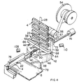
- the apparatus as shown in Figure 1 comprises a base plate 32, an applicator 34 having an application zone 36, and a staging zone 38 which is spaced from the application zone.
- a guide track 40 ( Figure 2) extends from the staging zone and into the application zone for guiding connectors into the application zone with the sidewalls of the connectors extending parallel to their path of movement along the guide track.
- the staging zone has a turntable 42 therein having first and second major surfaces 44,46 and a cylindrical circumferential surface 48.
- a hous-' ing-receiving recess 50 extends diametrically across the upper or first major surface 44 and is dimensioned to receive a single connector housing. This recess has first and second open ends 52, 53 which open onto the circumferential surface 48.
- the housing delivery system for delivering housings to the turntable comprises a wind-up spool 54 for the tape 28, guide rolls 56, 57 which guide the tape to the spool 54, and a guide plate 58 over which the tape is guided towards the upper surface of the turntable 42.
- the guide plate has a circular insert 60 therein in which there is provided an opening 62 through which the tape is advanced to the roll 56.
- this insert can be reversed and is provided with two or more openings so that tapes of varying widths can be used with the apparatus.
- a housing holder 64 is mounted on the plate 58 immediately above the upper or first surface 44 of the turntable 42.
- This housing holder has a sidewall 66 and endwalls 68 which extend to the surface of the plate 58. The lower portion of this plate thus defines the other sidewall of the holder.
- the holder is open on its upper side and on its lower side and is dimensioned such that an individual housing can fall therethrough onto the turntable 42.
- a notch 70 is provided on the internal surface of sidewall 66 for reception of the boss 22 of the housing.
- the individual housings are transported or fed from the staging zone to the application zone by a push rod 72 which extends from a pneumatic cylinder 74 and which is movable through the housing-receiving recess in the turntable.
- a force-applying member 76 ( Figure 9) is provided which can move downwardly and exert a force upon the cover portion of a housing to fully assemble the cover to the housing body as will be described below.
- the turntable can be rotated between the positions of Figures 2 and 3 and itwill be assumed that at the beginning of the operating cycle, the parts are in the positions of Figure 3.
- a connector housing 4 is positioned in the application zone 36
- the housing-receiving recess 50 is in alignment with the guide track 40
- a housing is in the housing-receiving recess
- another housing is resting in the housing holder 64.
- the operator of the machine is about to insert the end of a cable 6 into the application zone and position the end between the cover and the main body of the connector which is in the application zone 36.
- the cable pusher 72 immediately retracts to the position of Figure 6 and the turntable is rotated in a clockwise direction to the position of Figure 6 so that the housing-receiving recess 50 is beneath the housing holder 64.
- the housing which was previously in the holder drops down immediately into the recess and the turntable is then rotated in an anti-clockwise direction back to the position of Figure 4.
- the belt 28 is fed by a small amount and the next or leading connector on the belt is moved downwardly towards the open upper end of the holder 64.
- the leading connector is stripped from the belt and is deposited in the holder 64 in preparation for the next operating cycle. The operator is now free to insert the next cable into the application zone and repeat the entire cycle.
- the apparatus can be operated in either of two operating modes to place the polarizing boss 22 on the cable entry sidewall of the connector orto have the polarizing boss extending away from the cable as shown in Figure 16.
- the operating mode is such that the polarizing boss will project toward the cable-receiving side of the housing. If it is desired to have the connector installed in the other orientation so that the boss extends on the opposite side from the cable, an adjusting handle 78 is moved from the solid line position of Figure 2 to the dotted line position thereby to adjust the position of the turntable 42 in a counterclockwise direction through an angle of 90 degrees. If this adjustment is made, the machine will be placed in its second operating mode and the resulting connectors on the cable ends will have their polarizing bosses located on the opposite side from the cable entry sidewall of the housing.
- Figures 11 and 12 illustrate the operation of the apparatus when it is in the operating mode described above and shown in Figures 3 to 6.
- the housing-receiving recess is in its aligned position relative to the guide track and it is rotated between the position of Figure 11 and Figure 12 during each operating cycle, the recess being shown in its housing-receiving position in Figure 12.
- the position of the boss 22 of the connector is also indicated in Figures 12 and 13.
- the arrows indicate the direction of movement of the turntable from the positions shown.
- the housing-receiving recess 50 will be moved 90 degrees during the adjustment from the aligned position to the housing-receiving position.
- the rotary actuator (described below) is also moved through the 90 degree adjustment angle from the position of Figure 11 to the position of Figure 13.
- the turntable will be again rotated first in a clockwise direction from the position of Figure 13 to the position of Figure 14, and it will be seen that the position of the polarizing boss 22 on the connector which is fed to the application zone will now be on the opposite side of the feed track and the connector will be installed on the cable as shown by the connector on the left in Figure 16.
- the particular rotary actuator 85 which is briefly described below, used in the present embodiment of the invention is capable of only 90 degrees rotation in either a clockwise or anti- clockwise direction. Hence, the adjustment of the position of the turntable and of the actuator results in a reversal of the polarization of the connectors fed to the application zone as described above.
- the turntable is mounted on a support 80 which is in turn mounted in the support 32 for rotational adjustment through the 90 degree angle discussed above.
- the support 80 has a depending cylindrical flange 82 which is supported by suitable bearings 84 in he support plate 32.
- the actuator 85 for rotating the turntable is mounted concentrically in the cylindrical flange 82 and has a shaft 87 that extends to the turntable and is coupled to the turntable by a coupling 89.
- the arm 78 is latched in either of its two positions of adjustment by a latching mechanism which is cooperable with radially spaced-apart latching brackets 90, 91 ( Figure 10) on the surface of the plate 32.
- Each of these brackets has a recess or pocket 92 which receives a suitable spring- biased latching pin 86 on the arm.
- proximity switches 94, 96 are provided on the plate 32 and these proximity switches are actuated by switch actuators 98, 100 which are circumferentially spaced apart by an angle of 180 degrees. These switches and their actuators can, for example, be light actuated. Referring to Figure 10, it will be apparent that the actuator 100 is adjacent to the switch 96 and will, therefore, affect the condition of this switch. When the turntable is rotated through 90 degrees in a clockwise direction as viewed in Figure 10, the actuator 98 will be placed adjacent to the switch 94. It should be mentioned that the actuators 98, 100 are on the underside of the turntable and rotate with the turntable while the other structure shown in Figure 10 is mounted on the plate 32.
- shock absorbers are provided as shown at 102, 104 on the upper surface of the support plate 80. These shock absorbers are carried by a bracket 106 and engage the side surfaces of the switch actuators 98, 100.
- a light detector system is advantageously provided for detecting the presence or absence of a connector in the housing holder 64.
- This detector comprises a light source and a light detector 108, 110 which are on opposite sides of the turntable and which are located such that the light beam will be directed over the surface of the turntable and across the housing-receiving recess. If a connector is located in the recess, the light beam will be interrupted and this signal is also used to control the overall operation of the apparatus.
- the wind-up spool 54 for the tape 28 is advanced by a suitable actuator such as a motor 112 ( Figure 8) coupled through a slip clutch 114to the spool.
- a suitable actuator such as a motor 112 ( Figure 8) coupled through a slip clutch 114to the spool.
- a number of arrangements are suitable for advancing the tape by the short amount required during each operating cycle. It is desirable to provide a positive drive to the reel 56 and this is done by means of a timing belt 116 which is coupled to a pulley 118 mounted on a shaft on which the roll 56 is also mounted.
- the applicator for installing the connector on the end of the cable may be of any type and the applicator shown in Figure 9 is representative of a suitable type.
- the applicator has a housing in which there is provided a vertically reciprocable plate 120 having the previously identified pressure-applying member 76 thereon. Plate 120 is reciprocated during each operating cycle by a pneumatic piston-cylinder 122 which is coupled to the plate by a link 124. An apron 126 is provided in front of the application zone on which the cable is supported when it is inserted into the application zone.
- a hinged cover is provided for holding the connector in the zone as shown and the entire cycle can be initiated by a switch 130 which has a detector as shown at 128 adjacent to the applicator zone to detect the end of the cable when it is inserted through the partially assembled housing.
- the detector might take the form of a passageway for a light beam from the switch 130 or other detecting means.
- Suitable circuitry can be provided in housings as shown on the plate 32 for controlling the sequence of operations of the apparatus in accordance with the specific requirements of a specific application. Additional detector switches can be provided as required.
- the turntable can be normally aligned with the guide track and the connector delivery arranged to deliver connectors to the turntable in that position. During normal circumstances then, no rotation of the turntable would be required but rotation of 180 degrees would be required to change the operating mode.
Abstract
Description
- This invention relates to apparatus of the type which installs electrical connectors on flat conductor cables. The disclosed apparatus has a connector delivery system for feeding connectors to the application zone in either of two possible orientations for polarizing purposes.
- It is common practice to use flat conductor cables having a plurality of side-by-side coplanar conductors in an insulating sheath for making interconnections in many types of electrical devices such as computers and other complex electrical equipment. The connectors used for such flat cables are generally designed such that the connector can be installed on the cable by merely locating the cable in alignment with the terminals in the connnector annd pressing the cable into the wire-receivinng slots of the terminals. A variety of machines are available for performing the operations of installing the connectors on the cable ranging from extremely simple machines to relatively complex machines which have feeding systems for feeding the connectors to an application zone and a press in the application zone for installing the connectors on the cables. Ordinarily, connectors are supplied to the user as loose piece items and, where the machine has a feeding means for feeding the connectors to the application zone, the loose piece connectors are stacked in a magazine and advanced, one at a time, into the application zone when the machine is operated.
- The connectors of the type commonly used comprise an insulating housing having a rectangular cross section and having parallel sidewalls and parallel endwalls. It is possible to install an individual connector on a cable in either of two possible orientations and the particular orientation chosen will determine which conductors in the cable are connected to predetermined terminals in the connector. The cable will extend towards one of the elongated sidewalls of the housing with the end portions of the conductors connected to the terminals in the housing when the connector is in one of the two orientations and will extend towards the other (opposite) sidewall when the connector is in the other orientation. It is a desirable feature in applicators of this type that the applicator machine have the capability of installing the connector on the end of the cable in either of the two possible orientations. While some machines do have this capability, none of the presently available machines has this capability and, in addition, the capability of feeding the connectors from a belt which is wound on a reel. The presently available machines are designed such that they will accept only loose piece connectors.
- The present invention is directed to the achievement of an improved applicator for installing connectors on the ends of flat cable which has an automatic feeding or delivery system for delivering the connector housings to the application zone of an applicator in either of the two possible orientations. The invention is further directed to the achievement of an applicator which has the above-mentioned orientation feature in combination with a feeding system for feeding connectors mounted on a belt towards the applicator and delivering the connectors in the desired orientation to the applicator.
- The invention comprises an apparatus for installing electrical connectors on flat cables of the type having a plurality of conductors in side-by-side parallel relationship. The connectors are of the type comprising an insulating housing having oppositely directed faces, oppositely facing first and second sidewalls, and oppositely facing first and second endwalls, the endwalls and the sidewalls extending perpendicularly of the faces. The apparatus is of the type having an application zone, a housing applicator in the application zone for installing a housing in the application zone on a cable, a staging zone which is spaced from the application zone, and a housing guide track for guiding the housings from the staging zone into the application zone. A housing transporter is provided for moving the housings from the staging zone along the guide track and a housing delivery system is provided for delivering housings to the staging zone. The apparatus is characterized in that a turntable is provided in the staging zone which has first and second major surfaces and which has a circumferential cylindrical surface. A housing-receiving recess extends diametrically across the first major surface and has open first and second ends at the circumferential surface. The housing delivery system is effective serially to deliver housings to the housing-receiving recess with the first and second ends of the housing in the recess being adjacent to the first and second ends of the housing-receiving recess respectively. A turntable rotating means is provided for rotating the turntable through an angle of 180 degrees about an axis of rotation which extends centrally through the turntable whereby a housing delivered to the housing-receiving recess can be moved by the housing transporter along the guide track and into the application zone with the first endwall as the leading end or the second endwall of the housing as the leading end, thus to install the connector on a cable end in either of the two possible orientations.
- In accordance with further aspects and embodiments, the housing delivery system comprises a static housing holder mounted adjacent to the first major surface of the turntable. The housing holder has holder sidewalls and holder endwalls which extend perpendicularly with respect to the first major surface. The housing holder extends diametrically with respect to the turntable and has an open bottom and an open top and is dimensioned to permit a housing to move therethrough beyond the open bottom so that upon placement of a housing in the holder, the housing will move into the housing-receiving recess when the recess is aligned with the housing holder. The apparatus may be intended for use with housings which are removably attached to a continuous belt, such as a tape, in parallel spaced-apart relationship with sidewalls of the housings extending transversely of the length of the belt. The apparatus would have a belt feeder for feeding the belt to the staging zone and to the housing holder so that the leading housing on the belt is fed to a position in which it is in alignment with the open top of the housing holder. A housing stripper is preferably provided for stripping the leading housing from the belt whereby the leading housing is moved into the housing holder.
- In accordance with further embodiments, the turntable is rotatable between a loading position and an aligned position. The housing-receiving recess extends transversely of the guide track when the turntable is in the loading position and is aligned with the guide track when the turntable is in the aligned position, the turntable being rotatable selectively in a clockwise or in an anti- clockwise direction between the loading position and the aligned position. In accordance with a further embodiment, the turntable is rotatably adjustable through an adjustment angle of 90 degrees and is operationally rotatable through an operation angle of 90 degrees by the turntable rotating means. The orientation of the housings fed to the application zone is dependent upon the adjustment position of the turntable as determined by the adjusting means.
- FIGURE 1 is a perspective view of an apparatus in accordance with the invention.
- FIGURE 2 is a fragmentary perspective view showing only the essential elements of the apparatus including features of the application zone, the staging zone, and the delivery system for delivering connectors to the staging zone.
- FIGURES 3 to 6 are views similar to Figure 2 but showing the positions of the parts and the movement of the connectors during the various stages of an operating cycle of the apparatus.
- FIGURE 7 is a frontal view, partly in section, showing the staging zone and the application zone and showing features of the delivery system for delivering connectors to the staging zone.
- FIGURES 8, and 10 are views looking direction of the arrows 8-8, 9-9, and 10-10 of Figure 7.
- FIGURES 11 to 14 are diagrammatic views illustrating the manner in which the operating mode of the apparatus is changed.
- FIGURE 15 is a perspective view of a representative type of electrical connector for flat cables.
- FIGURE 16 is a side view of a section of cable having connectors as shown in Figure 15 installed on its ends, one of the connectors being one of the possible orientations and the other connector being in the other possible orientation.
- Referring first to Figures 1, 2 and 15, the
apparatus 2 of the invention installs or appliesconnectors 4 on the ends offlat cables 6. Each cable comprises a plurality of conductors in side-by-side relationship in an insulating sheath or the like. Eachconnector 4 comprises aninsulating housing 8 having oppositely directed first andsecond faces sidewalls second endwalls faces sidewalls 14 has a centrally located polarizingboss 22 projecting therefrom. As shown in Figure 16, this boss will project away from the end of the cable, as shown on the left, when the connector is in one of its two possible orientations and will project along the length of the cable or inwardly when the connector is in the other possible orientation. - The
housing 8 of theconnector 4 of the disclosed embodiment comprises two sections, acover 24 and a lowermain body 26. The cover is partially assembled to the main body and in installing the connector on a cable, the end of the cable is positioned between the cover and the upper surface of the main body. The cover is then moved downwardly into its fully assembled position, and in doing so, the individual conductors in the cable are inserted into slots in the terminals (not shown). - For convenience in storage, shipment, and handling, the connectors are removably secured to a belt or the like 28 and wound on a
reel 30. In the disclosed embodiment, the belt comprises a continuous length of tape which is adhesive on one surface. The connectors are adhered to the surface and the sidewalls of the connectors extend transversely of the length of the tape. - The apparatus as shown in Figure 1 comprises a
base plate 32, anapplicator 34 having anapplication zone 36, and astaging zone 38 which is spaced from the application zone. A guide track 40 (Figure 2) extends from the staging zone and into the application zone for guiding connectors into the application zone with the sidewalls of the connectors extending parallel to their path of movement along the guide track. - The staging zone has a
turntable 42 therein having first and secondmajor surfaces circumferential surface 48. A hous-' ing-receivingrecess 50 extends diametrically across the upper or firstmajor surface 44 and is dimensioned to receive a single connector housing. This recess has first and secondopen ends circumferential surface 48. - The housing delivery system for delivering housings to the turntable comprises a wind-up
spool 54 for thetape 28,guide rolls spool 54, and aguide plate 58 over which the tape is guided towards the upper surface of theturntable 42. The guide plate has acircular insert 60 therein in which there is provided anopening 62 through which the tape is advanced to theroll 56. Advantageously, this insert can be reversed and is provided with two or more openings so that tapes of varying widths can be used with the apparatus. When the wind-upspool 54 is rotated, a short length of tape is pulled from thereel 30 over the surface of theguide plate 58 and a connector is stripped from the tape as will be described below. - A
housing holder 64 is mounted on theplate 58 immediately above the upper orfirst surface 44 of theturntable 42. This housing holder has asidewall 66 andendwalls 68 which extend to the surface of theplate 58. The lower portion of this plate thus defines the other sidewall of the holder. The holder is open on its upper side and on its lower side and is dimensioned such that an individual housing can fall therethrough onto theturntable 42. Anotch 70 is provided on the internal surface ofsidewall 66 for reception of theboss 22 of the housing. - The individual housings are transported or fed from the staging zone to the application zone by a
push rod 72 which extends from apneumatic cylinder 74 and which is movable through the housing-receiving recess in the turntable. In the application zone, a force-applying member 76 (Figure 9) is provided which can move downwardly and exert a force upon the cover portion of a housing to fully assemble the cover to the housing body as will be described below. - The operation of the apparatus will now be described with reference to Figures 2 to 6, and this description will be followed by a description of other and more specific structural features of the apparatus.
- The turntable can be rotated between the positions of Figures 2 and 3 and itwill be assumed that at the beginning of the operating cycle, the parts are in the positions of Figure 3. It will be noted that a
connector housing 4 is positioned in theapplication zone 36, the housing-receivingrecess 50 is in alignment with theguide track 40, a housing is in the housing-receiving recess, and another housing is resting in thehousing holder 64. It is also assumed that the operator of the machine is about to insert the end of acable 6 into the application zone and position the end between the cover and the main body of the connector which is in theapplication zone 36. - When the operator inserts the
cable 6 into the connector, the control system forthe apparatus, as described below, is set into motion and the force-applyingmember 76 moves downwardly from the position of Figure 3 to the position of Figure 4. Thecover 24 is thereby moved to its fully assembled position and the connector is installed on the end of thecable 6. Immediately thereafter, the force-applyingmember 76 moves upwardly to its normal position, Figure 5, and substantially simultaneously, thepush rod 72 is advanced to push a connectorfrom therecess 50 along theguide track 40 and into the application zone. The connector which is being pushed into the application zone also causes the other connector, which has been installed on the cable, to be ejected as shown in Figure 5. - The
cable pusher 72 immediately retracts to the position of Figure 6 and the turntable is rotated in a clockwise direction to the position of Figure 6 so that the housing-receivingrecess 50 is beneath thehousing holder 64. When the recess and the holder are in alignment, the housing which was previously in the holder drops down immediately into the recess and the turntable is then rotated in an anti-clockwise direction back to the position of Figure 4. At this time, thebelt 28 is fed by a small amount and the next or leading connector on the belt is moved downwardly towards the open upper end of theholder 64. As the sidewall of the connector moves past theopening 62, the leading connector is stripped from the belt and is deposited in theholder 64 in preparation for the next operating cycle. The operator is now free to insert the next cable into the application zone and repeat the entire cycle. - The apparatus can be operated in either of two operating modes to place the
polarizing boss 22 on the cable entry sidewall of the connector orto have the polarizing boss extending away from the cable as shown in Figure 16. In Figures 3 to 5, the operating mode is such that the polarizing boss will project toward the cable-receiving side of the housing. If it is desired to have the connector installed in the other orientation so that the boss extends on the opposite side from the cable, an adjustinghandle 78 is moved from the solid line position of Figure 2 to the dotted line position thereby to adjust the position of theturntable 42 in a counterclockwise direction through an angle of 90 degrees. If this adjustment is made, the machine will be placed in its second operating mode and the resulting connectors on the cable ends will have their polarizing bosses located on the opposite side from the cable entry sidewall of the housing. - The manner in which the two operating modes are achieved can be understood from an inspection of Figures 11 to 14. Figures 11 and 12 illustrate the operation of the apparatus when it is in the operating mode described above and shown in Figures 3 to 6. In Figure 11, the housing-receiving recess is in its aligned position relative to the guide track and it is rotated between the position of Figure 11 and Figure 12 during each operating cycle, the recess being shown in its housing-receiving position in Figure 12. The position of the
boss 22 of the connector is also indicated in Figures 12 and 13. The arrows indicate the direction of movement of the turntable from the positions shown. - If the position of the turntable is adjusted in an anti-clockwise direction through an angle of 90 degrees from the position shown in Figure 11, the housing-receiving
recess 50 will be moved 90 degrees during the adjustment from the aligned position to the housing-receiving position. However, the rotary actuator (described below) is also moved through the 90 degree adjustment angle from the position of Figure 11 to the position of Figure 13. When the machine is subsequently operated, the turntable will be again rotated first in a clockwise direction from the position of Figure 13 to the position of Figure 14, and it will be seen that the position of thepolarizing boss 22 on the connector which is fed to the application zone will now be on the opposite side of the feed track and the connector will be installed on the cable as shown by the connector on the left in Figure 16. - The particular
rotary actuator 85, which is briefly described below, used in the present embodiment of the invention is capable of only 90 degrees rotation in either a clockwise or anti- clockwise direction. Hence, the adjustment of the position of the turntable and of the actuator results in a reversal of the polarization of the connectors fed to the application zone as described above. - Referring now to Figures 7, 8 and 10, the turntable is mounted on a
support 80 which is in turn mounted in thesupport 32 for rotational adjustment through the 90 degree angle discussed above. Thesupport 80 has a dependingcylindrical flange 82 which is supported bysuitable bearings 84 in he supportplate 32. Theactuator 85 for rotating the turntable is mounted concentrically in thecylindrical flange 82 and has ashaft 87 that extends to the turntable and is coupled to the turntable by acoupling 89. - The
arm 78 is latched in either of its two positions of adjustment by a latching mechanism which is cooperable with radially spaced-apart latchingbrackets 90, 91 (Figure 10) on the surface of theplate 32. Each of these brackets has a recess orpocket 92 which receives a suitable spring- biasedlatching pin 86 on the arm. To move the turntable and thesupport 80, it is merely necessary to withdraw the pin from the pocket in the one bracket and to swing the entire assembly until it is stopped by the other bracket and the pin moves into thepocket 92 of the other bracket. - A variety of possible control systems can be provided for the apparatus. In the disclosed embodiment, proximity switches 94, 96 are provided on the
plate 32 and these proximity switches are actuated byswitch actuators actuator 100 is adjacent to theswitch 96 and will, therefore, affect the condition of this switch. When the turntable is rotated through 90 degrees in a clockwise direction as viewed in Figure 10, theactuator 98 will be placed adjacent to theswitch 94. It should be mentioned that theactuators plate 32. - When the turntable is rotated, it must abruptly come to a stop in either of its two positions during each operating cycle. In order to dampen vibration, shock absorbers are provided as shown at 102, 104 on the upper surface of the
support plate 80. These shock absorbers are carried by abracket 106 and engage the side surfaces of theswitch actuators - As shown in Figure 8, a light detector system is advantageously provided for detecting the presence or absence of a connector in the
housing holder 64. This detector comprises a light source and alight detector - The wind-up
spool 54 for thetape 28 is advanced by a suitable actuator such as a motor 112 (Figure 8) coupled through a slip clutch 114to the spool. A number of arrangements are suitable for advancing the tape by the short amount required during each operating cycle. It is desirable to provide a positive drive to thereel 56 and this is done by means of atiming belt 116 which is coupled to apulley 118 mounted on a shaft on which theroll 56 is also mounted. - The applicator for installing the connector on the end of the cable may be of any type and the applicator shown in Figure 9 is representative of a suitable type. The applicator has a housing in which there is provided a vertically
reciprocable plate 120 having the previously identified pressure-applyingmember 76 thereon.Plate 120 is reciprocated during each operating cycle by a pneumatic piston-cylinder 122 which is coupled to the plate by alink 124. Anapron 126 is provided in front of the application zone on which the cable is supported when it is inserted into the application zone. A hinged cover is provided for holding the connector in the zone as shown and the entire cycle can be initiated by aswitch 130 which has a detector as shown at 128 adjacent to the applicator zone to detect the end of the cable when it is inserted through the partially assembled housing. The detector might take the form of a passageway for a light beam from theswitch 130 or other detecting means. - Suitable circuitry can be provided in housings as shown on the
plate 32 for controlling the sequence of operations of the apparatus in accordance with the specific requirements of a specific application. Additional detector switches can be provided as required. - A variety of alternative operating sequences can be used in the apparatus in accordance with the invention if desired. For example, the turntable can be normally aligned with the guide track and the connector delivery arranged to deliver connectors to the turntable in that position. During normal circumstances then, no rotation of the turntable would be required but rotation of 180 degrees would be required to change the operating mode.
- The operation of the apparatus is as above described with reference to Figure 3 to 6 and need not be further described here. It will be apparent that the apparatus is capable of installing connectors on the ends of cables in either of the orientations which are required. It will further be seen that a delivery system for efficiently delivering connectors to the staging zone and to the application zone is provided and that the advantages of reel feeding and tape mounting of the connectors are obtained in the practice of the invention.
Claims (10)
Priority Applications (1)
| Application Number | Priority Date | Filing Date | Title |
|---|---|---|---|
| AT85904727T ATE41564T1 (en) | 1984-10-25 | 1985-09-13 | DEVICE FOR ATTACHING CONNECTORS TO A FLAT CABLE WITH AN AUTOMATIC CONNECTOR FEED SYSTEM AND A SELECTIVE CONNECTOR ORIENTATION FEATURE. |
Applications Claiming Priority (2)
| Application Number | Priority Date | Filing Date | Title |
|---|---|---|---|
| US06/664,805 US4561178A (en) | 1984-10-25 | 1984-10-25 | Apparatus for installing connectors on flat cable having automatic connector delivery system and selective orientation feature for the connectors |
| US664805 | 1984-10-25 |
Publications (2)
| Publication Number | Publication Date |
|---|---|
| EP0197963A1 EP0197963A1 (en) | 1986-10-22 |
| EP0197963B1 true EP0197963B1 (en) | 1989-03-15 |
Family
ID=24667507
Family Applications (1)
| Application Number | Title | Priority Date | Filing Date |
|---|---|---|---|
| EP85904727A Expired EP0197963B1 (en) | 1984-10-25 | 1985-09-13 | Apparatus for installing connectors on flat cable having automatic connector delivery system and selective orientation feature for the connectors |
Country Status (8)
| Country | Link |
|---|---|
| US (1) | US4561178A (en) |
| EP (1) | EP0197963B1 (en) |
| JP (1) | JPS62500826A (en) |
| BR (1) | BR8507005A (en) |
| DE (1) | DE3568915D1 (en) |
| ES (1) | ES8705163A1 (en) |
| MX (1) | MX158000A (en) |
| WO (1) | WO1986002782A1 (en) |
Cited By (4)
| Publication number | Priority date | Publication date | Assignee | Title |
|---|---|---|---|---|
| US7065508B2 (en) | 1992-12-15 | 2006-06-20 | Sl Patent Holdings Llc | System and method for operating a licensing server |
| US7209901B2 (en) | 1992-12-15 | 2007-04-24 | Sl Patent Holdings Llc C/O Aol Time Warner | Method for selling, protecting, and redistributing digital goods |
| US7249103B2 (en) | 1992-12-15 | 2007-07-24 | Sl Patent Holdings, Inc. | System and method for selectively enabling access based on lineage analysis of digital information |
| US7831516B2 (en) | 1992-12-15 | 2010-11-09 | Sl Patent Holdings Llc | System and method for redistributing and licensing access to protected information among a plurality of devices |
Families Citing this family (10)
| Publication number | Priority date | Publication date | Assignee | Title |
|---|---|---|---|---|
| US4761879A (en) * | 1985-02-19 | 1988-08-09 | Burndy Corporation | Connector installation station for compact semi-automatic cable assembly system |
| US4852248A (en) * | 1985-02-19 | 1989-08-01 | Burndy Corporation | Connector installation station for compact semi-automatic cable assembly system |
| DE3601792C1 (en) * | 1986-01-22 | 1987-04-30 | Minnesota Mining & Mfg | Flat cable connection device |
| GB8725682D0 (en) * | 1987-11-03 | 1987-12-09 | Amp Holland | Connecting electrical connectors to cable |
| US4970778A (en) * | 1987-11-03 | 1990-11-20 | Amp Incorporated | Apparatus for connecting electrical connectors to cable |
| JPH01137091U (en) * | 1988-03-12 | 1989-09-19 | ||
| US5123808A (en) * | 1991-01-25 | 1992-06-23 | Amp Incorporated | Apparatus for loading connectors into connector applicators |
| US5444906A (en) * | 1993-09-02 | 1995-08-29 | The Whitaker Corporation | Machine for assembling a connector to the edge of a circuit board |
| US6331274B1 (en) | 1993-11-01 | 2001-12-18 | Nanogen, Inc. | Advanced active circuits and devices for molecular biological analysis and diagnostics |
| CN113385917B (en) * | 2021-06-15 | 2022-04-12 | 博众精工科技股份有限公司 | Jig buckling device and overturning and moving buckling mechanism |
Family Cites Families (5)
| Publication number | Priority date | Publication date | Assignee | Title |
|---|---|---|---|---|
| US3358852A (en) * | 1966-02-28 | 1967-12-19 | Western Electric Co | Apparatus for orienting, clamping, and rotating articles |
| US4148118A (en) * | 1978-03-17 | 1979-04-10 | Amp Incorporated | Apparatus for connecting pairs of wires |
| US4344225A (en) * | 1980-02-25 | 1982-08-17 | Amp Incorporated | Pre-assembly and terminating apparatus |
| US4372802A (en) * | 1980-06-02 | 1983-02-08 | Tokyo Denki Kagaku Kogyo Kabushiki Kaisha | Apparatus for mounting chip type circuit elements on printed circuit boards |
| US4481710A (en) * | 1982-10-28 | 1984-11-13 | Panduit Corp. | Tool for applying connectors |
-
1984
- 1984-10-25 US US06/664,805 patent/US4561178A/en not_active Expired - Lifetime
-
1985
- 1985-09-13 BR BR8507005A patent/BR8507005A/en not_active IP Right Cessation
- 1985-09-13 EP EP85904727A patent/EP0197963B1/en not_active Expired
- 1985-09-13 WO PCT/US1985/001738 patent/WO1986002782A1/en active IP Right Grant
- 1985-09-13 JP JP60504171A patent/JPS62500826A/en active Pending
- 1985-09-13 DE DE8585904727T patent/DE3568915D1/en not_active Expired
- 1985-10-22 MX MX355A patent/MX158000A/en unknown
- 1985-10-24 ES ES548164A patent/ES8705163A1/en not_active Expired
Cited By (12)
| Publication number | Priority date | Publication date | Assignee | Title |
|---|---|---|---|---|
| US7065508B2 (en) | 1992-12-15 | 2006-06-20 | Sl Patent Holdings Llc | System and method for operating a licensing server |
| US7085743B2 (en) | 1992-12-15 | 2006-08-01 | Sl Patent Holdings Llc | System and method for creating and running protected information |
| US7089212B2 (en) | 1992-12-15 | 2006-08-08 | Sl Patent Holdings Llc | System and method for controlling access to protected information |
| US7092908B2 (en) | 1992-12-15 | 2006-08-15 | Sl Patent Holdings Llc | System and method for selling protected information in an oem context |
| US7158954B2 (en) | 1992-12-15 | 2007-01-02 | Sl Patent Holdings Llc | System and method for processing protected video information |
| US7209901B2 (en) | 1992-12-15 | 2007-04-24 | Sl Patent Holdings Llc C/O Aol Time Warner | Method for selling, protecting, and redistributing digital goods |
| US7249103B2 (en) | 1992-12-15 | 2007-07-24 | Sl Patent Holdings, Inc. | System and method for selectively enabling access based on lineage analysis of digital information |
| US7330837B2 (en) | 1992-12-15 | 2008-02-12 | Sl Patent Holdings Llc | Method for adapting a software product to an environment |
| US7831516B2 (en) | 1992-12-15 | 2010-11-09 | Sl Patent Holdings Llc | System and method for redistributing and licensing access to protected information among a plurality of devices |
| US7962417B2 (en) | 1992-12-15 | 2011-06-14 | Sl Patent Holdings Llc | System and method for distributing protected information |
| US8140435B2 (en) | 1992-12-15 | 2012-03-20 | Sl Patent Holdings Llc | System and method for processing protected text information |
| US8332328B2 (en) | 1992-12-15 | 2012-12-11 | Sl Patent Holdings Llc | System and method for redistributing and licensing access to protected information among a plurality of devices |
Also Published As
| Publication number | Publication date |
|---|---|
| ES548164A0 (en) | 1987-04-16 |
| EP0197963A1 (en) | 1986-10-22 |
| ES8705163A1 (en) | 1987-04-16 |
| BR8507005A (en) | 1987-01-06 |
| DE3568915D1 (en) | 1989-04-20 |
| MX158000A (en) | 1988-12-29 |
| JPS62500826A (en) | 1987-04-02 |
| US4561178A (en) | 1985-12-31 |
| WO1986002782A1 (en) | 1986-05-09 |
Similar Documents
| Publication | Publication Date | Title |
|---|---|---|
| EP0197963B1 (en) | Apparatus for installing connectors on flat cable having automatic connector delivery system and selective orientation feature for the connectors | |
| EP0487505B1 (en) | Apparatus for assembling terminated wires into connectors to form electrical harnesses | |
| US5725140A (en) | Tape feeder for a surface mount placement system | |
| KR880000325B1 (en) | Tape loading apparatus | |
| EP0130743B1 (en) | Wire processing apparatus | |
| KR980008467A (en) | Devices for setting the fixing element on a rigid base | |
| US5695309A (en) | Electronic-component supplying cartridge and electronic-component supplying and pick-up apparatus | |
| US4290179A (en) | Cable harness assembly machine | |
| US4313251A (en) | System for applying electronic components to a circuit board | |
| EP0001891B1 (en) | Apparatus for inserting wires into electrical terminals | |
| US4403407A (en) | Multiple wire terminal applying | |
| US4757606A (en) | Method and apparatus for terminal insertion | |
| US4839962A (en) | Harness-making machine having improved cable guide | |
| US6353993B1 (en) | Cable finishing and resistance testing machine | |
| US6116822A (en) | Movable abutment for a component feeder | |
| US4360095A (en) | Feed chute for electronic components | |
| EP0498394A2 (en) | Apparatus for feeding articles from tube magazines | |
| US4899029A (en) | Electrical connector high-speed welding apparatus | |
| US5992611A (en) | Concurrent component mounter and method of concurrently mounting components | |
| JP2003017892A (en) | Electronic component supply apparatus | |
| US4703138A (en) | Protected switch unit for cassette tape recorder | |
| US4213286A (en) | Component sequencing and taping machine | |
| JP2839314B2 (en) | Wiring device for electrical connector | |
| US5519935A (en) | Machine for attaching preassembled connectors to ribbon cable | |
| JP3057179B2 (en) | Wiring device for electrical connector |
Legal Events
| Date | Code | Title | Description |
|---|---|---|---|
| PUAI | Public reference made under article 153(3) epc to a published international application that has entered the european phase |
Free format text: ORIGINAL CODE: 0009012 |
|
| 17P | Request for examination filed |
Effective date: 19860507 |
|
| AK | Designated contracting states |
Kind code of ref document: A1 Designated state(s): AT BE CH DE FR GB IT LI NL SE |
|
| 17Q | First examination report despatched |
Effective date: 19880531 |
|
| GRAA | (expected) grant |
Free format text: ORIGINAL CODE: 0009210 |
|
| ITF | It: translation for a ep patent filed |
Owner name: BARZANO' E ZANARDO MILANO S.P.A. |
|
| AK | Designated contracting states |
Kind code of ref document: B1 Designated state(s): AT BE CH DE FR GB IT LI NL SE |
|
| PG25 | Lapsed in a contracting state [announced via postgrant information from national office to epo] |
Ref country code: AT Effective date: 19890315 |
|
| REF | Corresponds to: |
Ref document number: 41564 Country of ref document: AT Date of ref document: 19890415 Kind code of ref document: T |
|
| REF | Corresponds to: |
Ref document number: 3568915 Country of ref document: DE Date of ref document: 19890420 |
|
| ET | Fr: translation filed | ||
| RAP4 | Party data changed (patent owner data changed or rights of a patent transferred) |
Owner name: AMP INCORPORATED (A NEW JERSEY CORPORATION) |
|
| NLT2 | Nl: modifications (of names), taken from the european patent patent bulletin |
Owner name: AMP INCORPORATED (A NEW JERSEY CORPORATION) TE HAR |
|
| PLBE | No opposition filed within time limit |
Free format text: ORIGINAL CODE: 0009261 |
|
| STAA | Information on the status of an ep patent application or granted ep patent |
Free format text: STATUS: NO OPPOSITION FILED WITHIN TIME LIMIT |
|
| 26N | No opposition filed | ||
| ITTA | It: last paid annual fee | ||
| REG | Reference to a national code |
Ref country code: GB Ref legal event code: 732E |
|
| EAL | Se: european patent in force in sweden |
Ref document number: 85904727.6 |
|
| PGFP | Annual fee paid to national office [announced via postgrant information from national office to epo] |
Ref country code: SE Payment date: 19950816 Year of fee payment: 11 |
|
| PGFP | Annual fee paid to national office [announced via postgrant information from national office to epo] |
Ref country code: BE Payment date: 19951002 Year of fee payment: 11 |
|
| PGFP | Annual fee paid to national office [announced via postgrant information from national office to epo] |
Ref country code: CH Payment date: 19951030 Year of fee payment: 11 |
|
| PGFP | Annual fee paid to national office [announced via postgrant information from national office to epo] |
Ref country code: GB Payment date: 19960808 Year of fee payment: 12 |
|
| PGFP | Annual fee paid to national office [announced via postgrant information from national office to epo] |
Ref country code: FR Payment date: 19960910 Year of fee payment: 12 |
|
| PG25 | Lapsed in a contracting state [announced via postgrant information from national office to epo] |
Ref country code: SE Effective date: 19960914 |
|
| PG25 | Lapsed in a contracting state [announced via postgrant information from national office to epo] |
Ref country code: LI Effective date: 19960930 Ref country code: CH Effective date: 19960930 Ref country code: BE Effective date: 19960930 |
|
| BERE | Be: lapsed |
Owner name: AMP INC. (UNE SOC. DE PENNSYLVANIE) Effective date: 19960930 |
|
| REG | Reference to a national code |
Ref country code: CH Ref legal event code: PL |
|
| EUG | Se: european patent has lapsed |
Ref document number: 85904727.6 |
|
| PG25 | Lapsed in a contracting state [announced via postgrant information from national office to epo] |
Ref country code: GB Free format text: LAPSE BECAUSE OF NON-PAYMENT OF DUE FEES Effective date: 19970913 |
|
| PG25 | Lapsed in a contracting state [announced via postgrant information from national office to epo] |
Ref country code: FR Free format text: THE PATENT HAS BEEN ANNULLED BY A DECISION OF A NATIONAL AUTHORITY Effective date: 19970930 |
|
| GBPC | Gb: european patent ceased through non-payment of renewal fee |
Effective date: 19970913 |
|
| PGFP | Annual fee paid to national office [announced via postgrant information from national office to epo] |
Ref country code: NL Payment date: 19980623 Year of fee payment: 14 |
|
| REG | Reference to a national code |
Ref country code: FR Ref legal event code: ST |
|
| PGFP | Annual fee paid to national office [announced via postgrant information from national office to epo] |
Ref country code: DE Payment date: 19980928 Year of fee payment: 14 |
|
| PG25 | Lapsed in a contracting state [announced via postgrant information from national office to epo] |
Ref country code: NL Free format text: LAPSE BECAUSE OF NON-PAYMENT OF DUE FEES Effective date: 20000401 |
|
| NLV4 | Nl: lapsed or anulled due to non-payment of the annual fee |
Effective date: 20000401 |
|
| PG25 | Lapsed in a contracting state [announced via postgrant information from national office to epo] |
Ref country code: DE Free format text: LAPSE BECAUSE OF NON-PAYMENT OF DUE FEES Effective date: 20000701 |