EP0186965A1 - Digital fail operational automatic flight control system utilising redundant dissimilar data processing - Google Patents
Digital fail operational automatic flight control system utilising redundant dissimilar data processing Download PDFInfo
- Publication number
- EP0186965A1 EP0186965A1 EP85308525A EP85308525A EP0186965A1 EP 0186965 A1 EP0186965 A1 EP 0186965A1 EP 85308525 A EP85308525 A EP 85308525A EP 85308525 A EP85308525 A EP 85308525A EP 0186965 A1 EP0186965 A1 EP 0186965A1
- Authority
- EP
- European Patent Office
- Prior art keywords
- computer
- computers
- channel
- disabling
- flight control
- Prior art date
- Legal status (The legal status is an assumption and is not a legal conclusion. Google has not performed a legal analysis and makes no representation as to the accuracy of the status listed.)
- Granted
Links
- 238000012545 processing Methods 0.000 title claims abstract description 229
- RZVHIXYEVGDQDX-UHFFFAOYSA-N 9,10-anthraquinone Chemical compound C1=CC=C2C(=O)C3=CC=CC=C3C(=O)C2=C1 RZVHIXYEVGDQDX-UHFFFAOYSA-N 0.000 title claims abstract description 152
- 238000012544 monitoring process Methods 0.000 claims abstract description 62
- 230000004044 response Effects 0.000 claims abstract description 14
- 238000006243 chemical reaction Methods 0.000 claims description 35
- 238000006467 substitution reaction Methods 0.000 claims description 4
- 230000009977 dual effect Effects 0.000 abstract description 14
- 238000004458 analytical method Methods 0.000 description 11
- 230000006870 function Effects 0.000 description 10
- 238000013461 design Methods 0.000 description 8
- 238000000034 method Methods 0.000 description 8
- 238000010200 validation analysis Methods 0.000 description 8
- 238000012795 verification Methods 0.000 description 8
- 230000000694 effects Effects 0.000 description 7
- 239000004020 conductor Substances 0.000 description 5
- 238000010586 diagram Methods 0.000 description 5
- 238000005516 engineering process Methods 0.000 description 5
- 238000013459 approach Methods 0.000 description 2
- 230000005540 biological transmission Effects 0.000 description 2
- 230000002950 deficient Effects 0.000 description 2
- 239000000835 fiber Substances 0.000 description 2
- 238000012360 testing method Methods 0.000 description 2
- 230000032258 transport Effects 0.000 description 2
- 230000001133 acceleration Effects 0.000 description 1
- 230000008901 benefit Effects 0.000 description 1
- 239000000969 carrier Substances 0.000 description 1
- 230000000295 complement effect Effects 0.000 description 1
- 238000004590 computer program Methods 0.000 description 1
- 238000010276 construction Methods 0.000 description 1
- 238000007796 conventional method Methods 0.000 description 1
- 230000008878 coupling Effects 0.000 description 1
- 238000010168 coupling process Methods 0.000 description 1
- 238000005859 coupling reaction Methods 0.000 description 1
- 238000001514 detection method Methods 0.000 description 1
- 230000002708 enhancing effect Effects 0.000 description 1
- 231100001261 hazardous Toxicity 0.000 description 1
- 230000001376 precipitating effect Effects 0.000 description 1
- 230000010076 replication Effects 0.000 description 1
- 238000013522 software testing Methods 0.000 description 1
- 230000036962 time dependent Effects 0.000 description 1
- 230000007704 transition Effects 0.000 description 1
- 230000000007 visual effect Effects 0.000 description 1
Images


Classifications
-
- G—PHYSICS
- G05—CONTROLLING; REGULATING
- G05D—SYSTEMS FOR CONTROLLING OR REGULATING NON-ELECTRIC VARIABLES
- G05D1/00—Control of position, course or altitude of land, water, air, or space vehicles, e.g. automatic pilot
- G05D1/0055—Control of position, course or altitude of land, water, air, or space vehicles, e.g. automatic pilot with safety arrangements
- G05D1/0077—Control of position, course or altitude of land, water, air, or space vehicles, e.g. automatic pilot with safety arrangements using redundant signals or controls
-
- G—PHYSICS
- G05—CONTROLLING; REGULATING
- G05B—CONTROL OR REGULATING SYSTEMS IN GENERAL; FUNCTIONAL ELEMENTS OF SUCH SYSTEMS; MONITORING OR TESTING ARRANGEMENTS FOR SUCH SYSTEMS OR ELEMENTS
- G05B9/00—Safety arrangements
- G05B9/02—Safety arrangements electric
- G05B9/03—Safety arrangements electric with multiple-channel loop, i.e. redundant control systems
-
- G—PHYSICS
- G06—COMPUTING; CALCULATING OR COUNTING
- G06F—ELECTRIC DIGITAL DATA PROCESSING
- G06F11/00—Error detection; Error correction; Monitoring
- G06F11/07—Responding to the occurrence of a fault, e.g. fault tolerance
- G06F11/16—Error detection or correction of the data by redundancy in hardware
- G06F11/1629—Error detection by comparing the output of redundant processing systems
- G06F11/1633—Error detection by comparing the output of redundant processing systems using mutual exchange of the output between the redundant processing components
-
- G—PHYSICS
- G06—COMPUTING; CALCULATING OR COUNTING
- G06F—ELECTRIC DIGITAL DATA PROCESSING
- G06F11/00—Error detection; Error correction; Monitoring
- G06F11/07—Responding to the occurrence of a fault, e.g. fault tolerance
- G06F11/16—Error detection or correction of the data by redundancy in hardware
- G06F11/20—Error detection or correction of the data by redundancy in hardware using active fault-masking, e.g. by switching out faulty elements or by switching in spare elements
- G06F11/202—Error detection or correction of the data by redundancy in hardware using active fault-masking, e.g. by switching out faulty elements or by switching in spare elements where processing functionality is redundant
- G06F11/2038—Error detection or correction of the data by redundancy in hardware using active fault-masking, e.g. by switching out faulty elements or by switching in spare elements where processing functionality is redundant with a single idle spare processing component
-
- G—PHYSICS
- G06—COMPUTING; CALCULATING OR COUNTING
- G06F—ELECTRIC DIGITAL DATA PROCESSING
- G06F11/00—Error detection; Error correction; Monitoring
- G06F11/07—Responding to the occurrence of a fault, e.g. fault tolerance
- G06F11/16—Error detection or correction of the data by redundancy in hardware
- G06F11/20—Error detection or correction of the data by redundancy in hardware using active fault-masking, e.g. by switching out faulty elements or by switching in spare elements
- G06F11/202—Error detection or correction of the data by redundancy in hardware using active fault-masking, e.g. by switching out faulty elements or by switching in spare elements where processing functionality is redundant
- G06F11/2043—Error detection or correction of the data by redundancy in hardware using active fault-masking, e.g. by switching out faulty elements or by switching in spare elements where processing functionality is redundant where the redundant components share a common memory address space
Definitions
- This invention relates to automatic control systems utilising digital control computers and has particular, but not exclusive reference to flight control systems for aircraft in connection with which it will in the main be discussed.
- Automatic flight control systems are constrained by U.S. Federal Air Regulations to provide safe control of the aircraft throughout the regimes in which the automatic flight control system is utilised. Any failure condition which prevents continued safe flight and landing must be extremely improbable. Present day regulations require a probability of less than 10- 9 failures per hour for flight critical components.
- a flight critical portion of an automatic flight control system is one, the failure of which will endanger the lives of the persons aboard the aircraft.
- the safety level of components of the system is determined by analysis, testing and field history procedures familiar to those skilled in the art. Such procedures are often referred to as verification and validation. Analysis of non-critical flight control system elements, however, typically need only be performed to at most a level of 10- 7 failures per hour. For example, components of an automatic flight control system utilised in automatically landing the aircraft may be designated as flight critical, whereas, certain components utilised during cruise control may be designated as non-critical.
- Dual redundancy is the utilisation of two identical channels with cross channel monitoring to detect a failure in one of the channels.
- cross channel monitoring does not provide effective detection of generic faults.
- a generic fault is defined as a fault that is inadvertently designed into a component such that all like components generically have this fault and respond in a like but defective manner.
- the cross channel monitoring detects the same although erroneous output from both channels and therefore does not detect the error.
- Such generic faults are also denoted as design errors.
- the absence of generic faults was traditionally proven by analysis and testing to the required level.
- a further problem engendered by the introduction of the programmed digital computer technology into automatic flight control systems is that the extensive software required is susceptible to generic design errors.
- An error can arise in the definition phase of software preparation as well as in the coding thereof.
- a generic design error can occur in the attendant assembler or compiler as well as in the micro-code for the processor.
- exhaustive verification and validation was often utilised to prove the absence of such generic design faults in the software as well as in the processor hardware to the required level. It is appreciated that such verification and validation procedures are exceedingly time consuming and expensive.
- Software based redundant systems have the unique characteristic attribute of being precisely identical.
- a generic fault in, for example, detail program code or processor hardware may result in a unique set of otherwise benign time-dependent events precipitating precisely the same hazardous response in all redundant systems at precisely the same time.
- the unique aspect of software systems to be precisely identical exacerbates the problems with generic faults in such systems.
- the entire channel must be certified in accordance with the "extremely improbable" rule discussed above with respect to flight critical aspects of the system.
- portions of the system utilised for performing non-critical functions must be certified to the same level as the critical portions since the non-critical portions are within the same computation complex as the critical portions.
- the automatic flight control technology has only recently advanced to the concept of dissimilar redundancy.
- dissimilar redundancy as currently utilised, dual dissimilar processors perform identical tasks utilising dissimilar software with cross channel monitoring to detect failures.
- a generic error designed into the processor or software of one channel will not exist in the processor or software of the other channel and the cross channel monitoring will detect the discrepancy.
- the remainder of the channel may then readily be analysed to the safety levels required by the U.S. Federal Air Regulations.
- the dissimilar computation apparatus and software need not be subject to the analysis which, as described above, is currently approaching impossibility.
- Such a prior art dual dissimilar processor system would be fail passive with respect to both random and generic faults.
- a random or generic fault occurring with respect to one of the dissimilar processors would be detected by the cross-channel monitoring and the dual dissimilar processor system passively disengaged.
- the present invention is defined in the appended claims and provides the first automatic flight control system that is fail operational with respect to a generic fault.
- the automatic flight control system of the present invention utilises at least two independent flight control subsystems, each comprising a pair of channels.
- One channel in each subsystem includes a first digital data processor and the other channel includes a second digital data processor with an active third processor.
- the two channels in each subsystem are cross-channel monitored to detect disagreements between the outputs of the first and second processors and between the outputs of the first and third processors. All of the processors perform the same automatic flight control and/or flight director system tasks, at least with respect to flight critical functions.
- the three processors in each subsystem provide dissimilar data processing with respect to each other.
- the two processors that do not have active third processors associated therewith in the respective subsystems provide dissimilar data processing with respect to each other.
- the six processors are arranged so that there are only three types of dissimilar data processing.
- the cross-channel monitoring in a subsystem detects a discrepancy between the outputs of the first and second processors, the output of the second processor is disabled and the active third processor continues servicing its channel. If the cross-channel monitoring detects a discrepancy between the outputs of the first and second processors and the outputs of the first and third processors, the entire subsystem is disengaged.
- the third processor is substituted for the second processor when the second processor is detected to be defective and if the substitution does not resolve the discrepancy, the subsystem is disengaged.
- This arrangement provides fail operational performance for a first random or generic failure and fail passive performance for a second random or generic failure.
- An alternative embodiment that is fail operational for the first two random failures and fail passive for a third random failure and which is fail operational for the first generic failure and fail passive for the second generic failure utilises three subsystems configured in the manner described.
- the three processors in the respective subsystems that do not have active third processors associated therewith provide dissimilar data processing with respect to each other.
- the dissimilar data processing, as implemented in the present invention may be effected by utilising dissimilar hardware, dissimilar software or both dissimilar hardware and dissimilar software.
- the channel 10 receives inputs from a sensor set 11 which may include conventional attitude, rate and acceleration sensors as well as other devices such as control wheel force sensors that are conventionally utilised in modern jet transports.
- the sensor set 11 may include such devices as directional and vertical gyroscopes, rate gyroscopes, and accelerometers.
- the sensor set 11 will include one or more inertial reference units for providing attitude information.
- the sensor set 11 may additionally include conventional radio guidance equipment such as VOR, DME and ILS receivers and the like as well as radio altimeters.
- the sensor set 11 may also include an air data computer for providing such parameters as barometric altitude, total air temperature, airspeed and the like.
- a flight management system may also be included in the sensor set 11 as well as aircraft control surface position and rate transducers, such as linear variable differential transformers, synchros, and tachometers as well as engine sensors.
- the sensor set 11 includes the required complement of analogue and digital sensors to provide signals for use in controlling the aircraft. It will be appreciated that included within the sensor set 11 are conventional analogue and digital signal processing circuits for preparing the sensor signals for entry into the channel 10. Such processing circuits include demodulators for synchro data and the like.
- the channel 10 includes an input data conversion portion 12 for receiving all of the signals from the sensor set 11 and converting these signals into a format suitable for application to a digital computer.
- the input data conversion portion 12 includes one or more conventional analogue-to-digital converters for converting the analogue signals from the sensor set 11 into digital format.
- the sensor signals from the sensor set 11 may have a variety of formats such as discrete voltage levels, variable voltage levels, amplitude modulated AC carriers, serial digital information in various formats and at various data rates and fibre optics information.
- the sensor data in whatever form it is provided by the sensor set is converted into the appropriate digital format for the computer.
- the input data conversion may, for example, include a digital bit serial to a digital bit parallel conversion, or a demodulation of a sensor signal.
- the analogue sensor signals are voltages related to conditions existing at various locations in the aircraft or may be serial or parallel digital data from, for example, an air data computer requiring serial-to-parallel conversion and/or level shifting.
- the channel 10 includes a digital processing element 13 responsive to the input signals from the input data conversion block 12.
- the processing element 13 includes a central processing unit (CPU), memory and computer programs (software) for performing operations upon the information provided by the sensor set 11 to produce responses to the aircraft for performing such functions as aircraft control.
- the channel 10 may have one or more processing elements associated therewith for reasons to be discussed.
- the channel 10 also includes an output data conversion portion 14 responsive to the outputs from the digital processing element 13 for converting the computer outputs in computer format into signals suitable for providing the variety of control and display functions required in the automatic flight control system.
- the output data conversion portion 14 will include one or more digital-to-analogue converters and additional equipment for formatting the signals.
- the output of the output data conversion portion 14 may be discrete voltage levels, single digits, light transmission for fibre optics, serial digital transmissions, voltages for servo valves to control hydraulic actuators for the aerodynamic control surfaces of the aircraft, and the like.
- the output data conversion portion 14 of the channel 10 receives signals in computer format and converts these signals to whatever format is required thereof.
- the outputs from the channel 10 are applied to aircraft control servos and/or flight director equipment 15 for providing conventional 3-axis control of the aircraft.
- the control servos and actuators may be of the well-known electro-mechanical or electro-hydraulic variety and are schematically representative of the total aircraft surface actuator system which may, in modern jet transports, be of the redundant variety.
- the channel 10 may also provide signals to conventional flight director instrumentation which provides visual commands to the pilot via attitude director instruments in a well known manner.
- the input data conversion electronic equipment 12 and the output data conversion electronic equipment 14 are analysed in a conventional manner to assure the absence of generic faults to the required level.
- the sensor set 11 and the aircraft control servos and/or flight director equipment 15 are configured in a traditional manner to meet the flight safety requirements of the Federal Air Regulations.
- the processing element 13 is utilised in a manner to be described so as to avoid effecting the traditionally required verification and validation procedures with respect thereto. Since the processing element 13 is exceedingly more complicated than the remainder of the system, it is virtually impossible to analyse so as to prove the absence of a design flaw or a generic fault to the extremely high confidence levels required by the U.S. Federal Air Regulations.
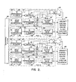
- the automatic flight control system of Figure 2 is fail operational for a first generic or random fault and is fail passive for a second generic or random fault.
- the system includes a first flight control computer (FCC) 20 which may be considered as a first subsystem of the automatic flight control system illustrated.
- the flight control computer 20 is of dual channel configuration with cross-channel monitoring.
- the flight control computer 20 includes first and second data processing channels 21 and 22, respectively.
- the channel 21 includes an input data conversion portion 23, a processing element 24 and an output data conversion portion 25 configured and intercoupled in a manner similar to the channel 10 described above with respect to Figure 1.
- the channel 22 similarly includes an input data conversion portion 26 and an output data conversion portion 27 as well as processing elements 28 and 29.
- the components of the channel 22 are configured and intercoupled in a manner similar to that described above with respect to the channel 10 of Figure 1 except that two processing elements are associated with the channel 22 instead of one processing element as illustrated in channel 10.
- the channel 22 also includes switches 30 and 31 coupling the processing elements 28 and 29, respectively, to the output data conversion portion 27.
- the switches 30 and 31 are arranged to disable the processing elements 28 and 29, respectively, from providing control signals from the channel 22.
- the channels 21 and 22 are cross coupled in a cross channel monitoring arrangement via leads 32 and 33 and cross-channel monitoring software within the processing elements 24, 28 and 29 to be further described hereinbelow.
- the lead 32 couples the output of the output data conversion portion 25 of the channel 21 with the input data conversion portion 26 of the channel 22.
- the lead 33 couples the output from the output data conversion portion 27 of the channel 22 with the input data conversion portion 23 of the channel 21.
- the processing element 24 contains a software segment for comparing the output of the channel 21 with the output of the channel 22 provided by the processing element 28 and provides a cross-channel comparison discrete signal on a lead 34 when a discrepancy is detected.
- the processing element 24 includes software for comparing the outputs of the channel 21 with the output of the channel 22 as provided by the processing element 29, providing a discrete signal on a lead 35 when a disagreement is discerned.
- the processing element 28 also includes cross-channel monitoring software for comparing the output from the channel 21 with the output from the channel 22 as provided by the processing element 28, providing a discrete signal on the lead 36 when a discrepancy is detected.
- the processing element 29 includes cross-channel monitoring software comparing the outputs from the channels 21 and 22 with respect to the processing element 29, and providing a discrete signal on a lead 37 when a disagreement is discerned. It will be appreciated that the leads 34-37 conveying the cross-channel monitoring discretes are illustrated as dashed lines, whereas the solid lines emanating from the elements 24, 28 and 29 convey data.
- the input data conversion portions 23 and 26 of the channels 21 and 22, respectively, receive sensor data from sensor sets 38. Sensors for providing signals related to aircraft and flight parameters are included within the block 38 in the manner described above with respect to the sensor set 11 of Figure 1.
- the outputs from the output data conversion portions 25 and 27 of the channels 21 and 22, respectively, are applied to aircraft control servos and/or flight director equipment 39.
- the aircraft control servos and/or flight director equipment 39 are of the type described above with respect to the block 15 of Figure 1.
- the cross-channel comparison discrete signals on the leads 35 and 37 are applied as inputs to an OR gate or element 40, the output of which is applied to actuate the switch 31.
- OR gate or element 40 the output of which is applied to actuate the switch 31.
- an OR gate or element 41 receives the cross-channel monitoring discrete signals on the leads 34 and 36 with respect to the cross-channel comparison involving processing element 28, thereby opening the switch 30 when a cross-channel monitoring discrete is provided on either the lead 34 or the lead 36.
- the outputs from the OR elements 40 and 41 are also applied as inputs to an AND gate or element 42.
- the output of the AND element 42 is applied to the aircraft control servos and/or flight director equipment 39 for disabling the servos and equipment 39 whenever both the OR elements 40 and 41 are enabled.
- the servos and equipment 39 may be disabled by the output from the AND element 42 by, for example, disconnecting the power to the servos. Conveniently, power to the servo engage coils or detents may be disconnected.
- the automatic flight control system illustrated in Figure includes a first subsystem comprising the flight control computer 20.
- the automatic flight control system also includes an independent subsystem comprising a flight control computer 50.
- the architecture of the flight control computer 50 is also dual-channel comprising channels 51 and 52.
- the arrangement and construction of the elements, except for the processing elements, of the flight control computer 50 are substantially the same as that described above with respect to the flight control computer 20.
- the elements 50 to 67 and 70 to 72 inclusive, of the flight control computer 50 correspond, respectively, to the elements 20 to 37 and 40 to 42 of the flight control computer 20.
- the servos and equipment 69 in the second subsystem replicate the servos and equipment 39 of the first subsystem.
- the input data conversion portions 53 and 56 of the respective channels 51 and 52 receive sensor data from the sensor set 38 in a manner to be explained.
- the processing elements 24, 28 and 29 of the flight control computer 20 provide dissimilar data processing with respect to each other and similarly the processing elements 54, 58 and 59 of the flight control computer 50 also provide dissimilar data processing with respect to each other. It is also necessary in accordance with the invention that the processing elements in the channels that only have one processing element associated therewith; viz, the elements 24 and 54, provide dissimilar data processing with respect to each other.
- the processing elements 24, 28 and 29 of the flight control computer 20 provide data processing of the C, A and B types, respectively.
- the processing elements 54, 58 and 59 of the flight control computer 50 provide data processing of the B, A and C types, respectively.
- the data processing type of any of the processing elements in the system is selected from a group consisting of three dissimilar types. Therefore, it is seen that processing elements 24, 28 and 29 provide dissimilar data processing with respect to each other as do the processing elements 54, 58 and 59. Furthermore, the processing elements 24 and 54 provide dissimilar data processing with respect to each other.
- the dissimilar data processing may be effected by dissimilar hardware, dissimilar software or both dissimilar hardware and dissimilar software. If only generic faults associated with the software are of concern, then the hardware of the processing elements may be identical.
- Dissimilar hardware may be effected by utilising three processing elements of.different electrical and logic design which additionally may be manufactured by different manufacturers.
- the software may be rendered dissimilar by utilising three distinct teams of program designers providing three distinct program specifications and three separate teams of programmers writing dissimilar code in dissimilar languages.
- the assemblers and compilers utilised for each type of data processing may also be dissimilar with respect to each other as may the software operating systems and executive code for each type of data processing.
- the software support procedures such as software testing may also be rendered dissimilar by utilising dissimilar procedures and personnel. The tasks, however, that each processing element performs are similar with respect to each other.
- the automatic flight control system specification including aircraft control laws and mode transition criteria are common to all three data processing type elements.
- three dissimilar computer types are utilised which are manufactured and are available from the Applicants of the present application. These computers are the SDP 175-2, the SDP 275 and SDP 375. These computers are designed for airborne applications.
- the SDP 175-2 microprocessor was designed and developed by the present Applicants.
- the SDP 275 is based on the Z8002 microprocessor.
- the SDP 375 is based on the 8086-8087 Intel microprocessor design.
- Each of these three computer types has its own distinct assembler. It will be appreciated that although three specific computer types are delineated above, any three types of processing elements that provide dissimilar data processing with respect to each other may be utilised in practicing the invention.
- Figure 3A illustrates the processing elements 28, 29, 58 and 59 of Figure 2
- Figure 3B illustrates the processing elements 24 and 54 of Figure 2.
- an input-output section 80 of the processing element receives inputs from the associated input data conversion block of Figure 2 and provides data outputs on a lead 81 to the switch associated with the processing element.
- the input-output section 80 also provides a discrete signal on a lead 82 via a latch 83 to the associated OR gate of Figure 2.
- the discrete signal on the lead 82 is provided as a result of cross-channel comparison monitoring in a manner to be explained.
- the processing element of Figure 3A includes a cross-channel comparison monitoring capability illustrated schematically at reference numeral 84.
- the cross-channel monitoring 84 compares the output from the other channel of the flight control computer in which the processing element of Figure 3A is located with the output of the channel in which it itself is located and sets into the latch 83 a discrete signal whenever the cross-channel monitoring 84 detects disagreement between the two channels.
- the processing element of Figure 3A also includes the capability of performing the numerous automatic flight control and/or flight director tasks required of the automatic flight control system of Figure 2. This task performance capability is schematically illustrated at reference numeral 85. The results of performing the tasks 85 are communicated via the input/output 80 to the switch associated with the processing element and then to the output data conversion portion of the channel in which the processing element is located.
- the processing element of Figure 3B includes an input/output section 90 for receiving data from the input data conversion portion of the channel of Figure 2 in which the processing element is utilised and for providing data via a lead 91 to the output data conversion portion of Figure 2 associated with the processing element.
- the input/output section 90 also provides cross-channel monitoring discrete signals on leads 92 and 93 which are set into latches 94 and 95, respectively.
- the outputs from the latches 94 and 95 are coupled, respectively, to the two OR gates included in the flight control computer in which the processing element is located as illustrated in Figure 2.
- the processing element of Figure 3B includes a cross-channel monitoring capability illustrated schematically at reference numeral 96.
- the cross-channel monitoring 96 of the processing element of Figure 3B compares the output provided by the channel in which the processing element of Figure 3B is located with the outputs from the other channel of the flight control computer provided by the two respective processing elements associated with the other channel. When a disagreement occurs between the output of the channel that includes the'processing element of Figure 3B and the output of the other channel due to one of the two processing elements associated therewith, a cross-channel monitoring discrete signal is set into the latch 94. If the disagreement is due to the output of the other processing element associated with the other channel of the flight control computer, the cross-channel monitoring discrete signal is set into the latch 95.
- the processing element of Figure 3B includes the capability of performing automatic flight control and/or flight director tasks indicated schematically at reference numeral 97. These tasks are identical to those discussed above with respect to reference numeral 85 of Figure 3A.
- the cross channel comparison monitoring in the flight control computer 50 compares the outputs of the channels 51 and 52 to detect discrepancies therebetween.
- Each of the processing elements in each of the flight control computers performs the full set of three axis critical tasks required in the control of the aircraft. It will be appreciated that not all of the processing element outputs need be utilised to drive the aircraft control servos and flight director equipment.
- the channel 21 of the flight control computer 20 may be utilised to provide aircraft control with respect to the longitudinal axis of the aircraft via the servos and equipment 39, and the channel 22 may provide the lateral axis aircraft control via the servos and equipment 39.
- the channel 51 of the flight control computer 50 may provide longitudinal axis control via the servos and equipment 69 and the channel 52 lateral axis control via the servos and equipment 62.
- the various leads illustrated in Figure 2 may be multi-conductor buses conveying pluralities of signals.
- the leads 32 and 33 are multi-conductor buses intercoupling all of the outputs of the output data conversion sections of the channels to the input data conversion sections of the opposite channels so that the cross-channel monitoring functions may be performed within the processing elements. Some of these conductors of these buses also go to the servos and equipment 39 as described above to provide control of the aircraft in all of its axes.
- the leads illustrated with respect to the flight control computer 50 may be multi-conductor buses interconnecting the elements illustrated therein and the servos and equipment 69.
- the leads 81 and 91 of the processing elements illustrated in Figures 3A and 3B are also multi-conductor buses conveying pluralities of data signals.
- the cross-channel monitoring in the flight control computer 20 will detect a disagreement between the channels 21 and 22 and the cross-channel monitoring of the flight control computer 50 will detect a disagreement between the channels 51 and 52.
- the cross-channel monitoring 84 ( Figure 3A) of the processing element 28 will provide a cross-channel comparison disagreement signal to the latch 83 ( Figure 3A) and thus via the lead 36 to the OR gate 41.
- the cross-channel monitoring 96 ( Figure 3B) of the processing element 24 will set a cross-channel monitoring disagreement signal into the latch 94 ( Figure 3B) and thus apply this disagreement discrete signal via the lead 34 to the OR gate 41.
- the faulted A type processing element 58 of the flight control computer 50 is disabled via the cross-channel monitoring discretes 64 and 66 through the OR gate 71 deactuating the switch 60.
- the channel 52 of the flight control computer 50 also retains full processing capability via the C type processing element 59.
- the automatic flight control system illustrated in Figure 2 remains fully operational with full cross-channel monitoring in each flight control computer.
- the system retains a dual-dual configuration. That is, the flight control computer 20 retains fully operational channels 21 and 22 with cross-channel monitoring and the flight control computer 50 retains channels 51 and 52 with cross-channel monitoring.
- the system of Figure 2 is fail operational after a first generic failure of the A type processing element.
- the cross-channel monitoring discretes that were enabled because of this failure remain stored in the latches 83 and 94 ( Figures A and 3B) of the processing elements 24, 28, 54 and 58, thus maintaining the OR gates 41 and 71 enabled.
- channels 22 and 21 of the flight control computer 20 have B and C type processing elements, respectively, associated therewith and the channels 51 and 52 of the flight control computer 50 also have B and C type processing elements associated therewith, respectively.
- the next generic fault that is manifested in either the B type processing elements or the C type processing elements will result in a cross channel miscomparison in both flight control computers 20 and 50 resulting in a passive shutdown of the entire system.
- the second generic failure will result in enablement of the OR gates 40 and 70, thereby enabling the AND gates 42 and 72, thus disabling the servos and equipment 39 and 69 from providing further control of the aircraft.
- the automatic flight control system of Figure 2 again fails operatively but retains a different configuration from that described above.
- the failure of the B type processing element 29 results in the enablement of the OR gate 40 and the disablement of the switch 31, thereby preventing the processing element 29 from providing further outputs for the channel 22.
- the flight control computer 20 retains two fully operative channels with operative cross-channel comparison monitoring.
- the channel 21 retains the C type processing element 24 and the channel 22 retains the A type processing element 28.
- the failure discretes resulting from the cross-channel monitoring that detected the failure are latched into the processing elements 24 and 29 to maintain enabling signals on the leads 37 and 35, thereby maintaining the OR gate 40 enabled.
- the failure of the type B processing element 54 results in a miscomparison between the outputs of both the A type processing element 58 and the C type processing element 59 on the opposite channel. This results in cross-channel discretes on all of the leads 64, 65, 66 and 67 enabling both OR gates 70 and 71 and therefore the AND gate 72. Enablement of the AND gate 72 disables the servos and equipment 69 thereby shutting down the subsystem of the automatic flight control system comprising the flight control computer 50 and the servos and equipment 69.
- the automatic flight control system remains operational because of the operative and fully monitored state of the subsystem comprising the flight control computer 20 and the servos and equipment 39.
- the next generic failure in either the C type processing element 24 or the A type processing element 28 will be detected by the cross-channel monitoring between the channels 21 and 22 resulting in passive disablement of the subsystem comprising the flight control computer 20 and the servos and equipment 39.
- a first generic failure in the C type processing elements 24 and 59 results in the failure configuration just described except that after this first failure, the subsystem comprising the flight control computer 50 and the servos and equipment 69 remains operational, whereas the subsystem comprising the flight control computer 20 and the servos and equipment 39 is passively disabled.
- the failed configuration retains the channel 51 with the B type processing element 54 and the channel 52 with the A type processing element 58.
- the channels 51 and 52 again retain complete cross-channel monitoring capabilities.
- a second generic failure in either the A type processing element 58 or the B type processing element 54 results in passive disablement of the subsystem comprising the flight control computer 50 and the servos and equipment 69 in a manner similar to that described above.
- two independent subsystems are utilised, one comprising the flight control computer 20 with the servos and equipment 39 and the other comprising the flight control computer 50 with the servos and equipment 69.
- the cross-channel comparison monitoring in each subsystem is such that if only one of the processing elements in the channel having two processing elements disagrees with the channel having one processing element, the involved processing element in the two processing element channel is disabled from further control of the aircraft. If, however, both processing elements in the channel having two processing elements disagree with the channel having the single processing element, the entire subsystem is disabled.
- the described architecture may also be considered as having a channel with a primary processing element and an active standby processing element that is substituted for the primary processing element if a generic failure should occur with respect to the primary processing element. If replacement does not resolve the disagreement, the subsystem is then disabled.
- the channel 22 may be considered as having a primary processing element 28 and a standby processing element 29. With appropriate logic actuating the switches 30 and 31, the processing element 29 may be substituted for the processing element 28 and the processing element 24. If this substitution does not resolve the disagreement between the channels 21 and 22, the servos and equipment 39 would be disabled as previously described.
- the automatic flight control system of Figure 2 is fail operational in response to a first generic fault and fail passive in response to a second generic fault.
- the sensor sets 38 and the servos and equipment 39 and 69 in combination with the flight control computers 20 and 50 must also exhibit these characteristics.
- the sensor sets 38 may include redundancy, monitoring and voting to achieve the characteristics.
- three sensor sets are traditionally utilised, particularly with respect to those sensors providing data for the critical modes of the flight regimes. It a fault occurs in one set, the two remaining sets may be utilised to provide the data and for cross-sensor comparison. When the two remaining sets fail to agree, the entire system is shut down.
- each of the blocks 39 and 69 represent a full set of control servos and/or flight director equipment for providing all of the aircraft control and flight director functions for the aircraft.
- the flight control computers 20 and 50 are utilised to monitor the performance of the servos and equipment 39 and 69 respectively.
- Servo position and rate transducers coupled to control surface actuators are included in the blocks 39 and 69 and provide inputs (not shown) to the sensor sets 38 for end around inputting into the flight control computers 20 and 50.
- the flight control computers 20 and 50 can monitor the performance of the servos and equipment 39 and 69, respectively, disabling either set of servos and equipment if a failure is detected.
- the involved subsystem of the automatic flight control system of Figure 2 is disabled. This leaves operational the remaining subsystem with its servos and equipment to maintain control of the aircraft until a second failure in that subsystem causes a shutdown of the entire flight control system.
- each of the blocks 39 and 69 are monitored and compared by the associated flight control computer to detect failures as described.
- the flight control computers 20 and 50 provide inputs to the associated servos and equipment, monitor the outputs from the associated servos and equipment and enable and disable the servos and equipment for providing the desired failure characteristics.
- each of the servos and equipment blocks 39 and 69 may comprise multiply redundant sets for achieving the desired failure characteristic.
- three redundant sets of servos and equipment would provide fail operational performance.
- Such redundant servos may utilise conventional force summing and cam-out techniques to remain operational in response to a failure.
- An additional advantage derived from utilising the present invention relates to software or hardware changes introduced after certification of the flight control system by the U.S. Federal Aviation Authority. The possibility that such changes to software or hardware would result in an undetected error is essentially eliminated. Such errors could occur in coding, or in complex integrated circuits such as microprocessors.
- the servos and equipment 39 may be disabled.
- a similar arrangement could be included in the flight control computer 50. It will be appreciated that the dual-dual channel configuration for automatic flight control systems provides fail operational performance for random failures.
- the dual-dual configuration of the automatic flight control system of Figure 2 utilising the invention provides the same fail operational response to a generic failure. In both situations, only one of the dual channel subsystems is disabled in response to the first failure.
- the processing elements included in the flight control computers of Figure 2 perform the same tasks utilising dissimilar data processing. If the cross-channel monitoring with respect to the two processing elements in one of the channels of each flight control computer indicates agreement with the processing element of the other channel of the flight control computer, then the output can be taken from either channel for application to the aircraft control servos and/or flight director equipment. Additionally, where the cross-channel monitoring indicates agreement, the output from the channel having two processing elements may be derived from either of the two elements.
- the redundancy and cross-channel monitoring configuration described above is only utilised for critical functions. A non-critical function may be provided by only one channel of each flight control computer without utilising cross-channel monitoring. For such non-critical mode implementations, traditional verification and validation procedures may be utilised.
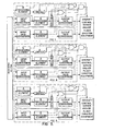
- the A-type processing elements 28 and 58 in the channels 22 and 52 of the flight control computers 20 and 50, respectively, may be considered as the primary processors for the channels with the B-type and C-type processing elements 29 and 59 considered as secondary active standby processors.
- an alternative, but equivalent, configuration may be provided utilising dissimilar processing element types for the primary processors with the same type of processing element utilised as the secondary element in the channel.
- Such an arrangement is illustrated in Figure 4. It will be appreciated that the embodiment of Figure 4 is identical to that of Figure 2 except for the arrangement of the A, B and C-type processing elements with respect to the channels. Further discussion, therefore, of the details of the Figure 4 embodiment will be omitted for brevity.
- the failure modes of the Figure 4 embodiment are similar to that described above with respect to Figure 2.
- the automatic flight control system of Figure 4 is fail operational with respect to the first generic fault and fail passive with respect to the second generic fault.
- the subsystem including the flight control computer 2 will be disabled in response to a first generic failure in the A-type processing element with the subsystem including flight control computer 1 providing continued fail passive performance. If the first generic failure occurs in the B-type processing element, the subsystem including flight control computer 1 is disabled with the subsystem including flight control computer 2 continuing operation. Should the first generic failure occur in the C-type processing element, both subsystems will remain operational in a full passive status.
- an automatic flight control system is illustrated that is fail operational for a first generic fault and fail passive for a second generic fault, but is fail operational squared with respect to random faults.
- the system of Figure 5 will remain operational after two consecutive random failures and will be fail passive with respect to a third random failure.
- the automatic flight control system of Figure 5 utilises three subsystems, each having a flight control computer (FCC) 1, 2, 3 and dedicated aircraft control servos and/or flight director equipment in a manner similar to that described above with respect to Figure 2.
- FCC flight control computer
- the processing elements in each FCC provide dissimilar data processing with respect to each other.
- the sensor sets of Figure 5 should be configured, in a conventional manner, to provide the fail operational squared characteristic of the architecture of the system illustrated. In a well known manner, four sensor sets for the critical data provide the desired characteristics.
- a second signal may be provided by the processing element 24 for disabling the servos and equipment 39 in the event both of the processing elements 28 and 29 disagree with the processing element 24.
- Suitable comparison outputs from the processing elements 28 and 29 may also control the switch and disable the servos and equipment 39 in a similar manner. Additionally, the arrangement may also be used in implementing the other subsystem in Figure 2 as well as the subsystems of Figures 4 and 5.
Abstract
Description
- This invention relates to automatic control systems utilising digital control computers and has particular, but not exclusive reference to flight control systems for aircraft in connection with which it will in the main be discussed.
- Automatic flight control systems are constrained by U.S. Federal Air Regulations to provide safe control of the aircraft throughout the regimes in which the automatic flight control system is utilised. Any failure condition which prevents continued safe flight and landing must be extremely improbable. Present day regulations require a probability of less than 10-9 failures per hour for flight critical components. A flight critical portion of an automatic flight control system is one, the failure of which will endanger the lives of the persons aboard the aircraft. Generally, the safety level of components of the system is determined by analysis, testing and field history procedures familiar to those skilled in the art. Such procedures are often referred to as verification and validation. Analysis of non-critical flight control system elements, however, typically need only be performed to at most a level of 10-7 failures per hour. For example, components of an automatic flight control system utilised in automatically landing the aircraft may be designated as flight critical, whereas, certain components utilised during cruise control may be designated as non-critical.
- Automatic flight control systems utilising analogue computers and components had been prevalent in the art wherein it had been completely practical to perform the verification and validation procedures to certify conformance of such systems to the safety requirements of the Federal Air Regulations. Traditionally, such analogue systems utilised independent control of the aircraft axes by providing, for example, independent pitch and roll control channels. Certification analysis was facilitated by the axis independent control. A hardover failure, for example, in the pitch or roll axis affected only that axis.
- A known technique for enhancing automatic flight control system reliability is that of dual redundancy. Dual redundancy is the utilisation of two identical channels with cross channel monitoring to detect a failure in one of the channels. Although such systems are effective against random faults, cross channel monitoring does not provide effective detection of generic faults. A generic fault is defined as a fault that is inadvertently designed into a component such that all like components generically have this fault and respond in a like but defective manner. When identical components having a generic fault are in respective redundant channels, the cross channel monitoring detects the same although erroneous output from both channels and therefore does not detect the error. Such generic faults are also denoted as design errors. In the prior art, in order to satisfy the U.S. Federal Air Regulations, the absence of generic faults was traditionally proven by analysis and testing to the required level.
- Such prior art dual redundant systems with identical channels provided fail passive performance with respect to random faults. When the cross-channel monitoring detected different outputs from the two channels, the dual channel automatic flight control system was disengaged thereby failing in a passive manner. In order to effect fail operational performance with respect to random faults, two such dual redundant channel pairs have been conventionally utilised, whereby a miscomparison in one pair would result in shut down of that pair with the other channel pair remaining in operation. The occurrance of a second random fault in the remaining channel pair would effect passive shut down of the system. For the reasons discussed above, such multiply redundant systems were ineffectual in detecting generic faults.
- In present day technology, stored program digital computers are supplanting the analogue computer of the prior art technology. It has generally been found that a digital computer including the hardware and software is of such complexity that the verification and validation analysis for certification in accordance with U.S. Federal Air Regulations is exceedingly more time consuming, expensive and difficult than with the analogue computer. The level of complexity and sophistication of the digital technology is increasing to the point where analysis and proof of certification to the stringent safety requirements is approaching impossibility. Such digital systems possess an almost unlimited number of unique failure modes and indeterminable effects. To further exacerbate the difficulty, current day digital flight control computers perform all of the computations for all of the control axes of the aircraft in the same "black box" unlike in the analogue computer approach where the control of the aircraft axes was provided by separate respective "black boxes". It will be appreciated that modern aircraft are stressed to withstand hardovers in the pitch axis or the roll axis but not in both axes simultaneously.
- A further problem engendered by the introduction of the programmed digital computer technology into automatic flight control systems is that the extensive software required is susceptible to generic design errors. An error can arise in the definition phase of software preparation as well as in the coding thereof. A generic design error can occur in the attendant assembler or compiler as well as in the micro-code for the processor. In the prior art, in order to satisfy the stringent safety requirements of the U.S. Federal Air Regulations, exhaustive verification and validation was often utilised to prove the absence of such generic design faults in the software as well as in the processor hardware to the required level. It is appreciated that such verification and validation procedures are exceedingly time consuming and expensive. Software based redundant systems have the unique characteristic attribute of being precisely identical. Accordingly, a generic fault in, for example, detail program code or processor hardware may result in a unique set of otherwise benign time-dependent events precipitating precisely the same hazardous response in all redundant systems at precisely the same time. Thus the unique aspect of software systems to be precisely identical exacerbates the problems with generic faults in such systems.
- For the reasons given above, it will be appreciated that redundant identical channels of digital data processing with cross channel monitoring may not detect hardware and software generic design errors so that reliability can be certified to the required level. Furthermore, with the increasingly complex and sophisticated digital processing being incorporated into automatic flight control systems, it is approaching impossibility to prove by analysis the absence of such generic errors to the levels required by the U.S. Federal Air Regulations. It will be appreciated that in a digital flight control channel, including a digital computer, sensors, input and output processing apparatus, and control servos, all of the processing for all aircraft axes are performed in the same computer and critical as well as non-critical functions are controlled by the same channel. Thus, the entire channel must be certified in accordance with the "extremely improbable" rule discussed above with respect to flight critical aspects of the system. Thus, even those portions of the system utilised for performing non-critical functions must be certified to the same level as the critical portions since the non-critical portions are within the same computation complex as the critical portions.
- In order to overcome these problems, the automatic flight control technology has only recently advanced to the concept of dissimilar redundancy. In dissimilar redundancy, as currently utilised, dual dissimilar processors perform identical tasks utilising dissimilar software with cross channel monitoring to detect failures. With this approach, a generic error designed into the processor or software of one channel will not exist in the processor or software of the other channel and the cross channel monitoring will detect the discrepancy. The remainder of the channel may then readily be analysed to the safety levels required by the U.S. Federal Air Regulations. The dissimilar computation apparatus and software, however, need not be subject to the analysis which, as described above, is currently approaching impossibility.
- Such a prior art dual dissimilar processor system would be fail passive with respect to both random and generic faults. A random or generic fault occurring with respect to one of the dissimilar processors would be detected by the cross-channel monitoring and the dual dissimilar processor system passively disengaged.
- None of the prior art system configurations discussed above provide fail operational performance with respect to generic faults. The utilisation of multiple dual redundant systems with similar processing elements fails to detect generic faults for the reasons discussed above. A mere replication of dual channel subsystems utilising dissimilar processing elements would result in a fail passive capability rather than the fail operational performance that such a system configuration would be expected to provide. This is because a generic fault detected in one dual subsystem causing that subsystem to be disengaged would be present in the corresponding element in the other subsystem also resulting in disengagement thereof. Thus this dual-dual dissimilar configuration instead of providing fail operational performance, as is expected from this system arrangement, results in a fail passive system which is the property otherwise obtainable from one half the system.
- The present invention is defined in the appended claims and provides the first automatic flight control system that is fail operational with respect to a generic fault. The automatic flight control system of the present invention utilises at least two independent flight control subsystems, each comprising a pair of channels. One channel in each subsystem includes a first digital data processor and the other channel includes a second digital data processor with an active third processor. The two channels in each subsystem are cross-channel monitored to detect disagreements between the outputs of the first and second processors and between the outputs of the first and third processors. All of the processors perform the same automatic flight control and/or flight director system tasks, at least with respect to flight critical functions. The three processors in each subsystem provide dissimilar data processing with respect to each other. The two processors that do not have active third processors associated therewith in the respective subsystems provide dissimilar data processing with respect to each other. The six processors are arranged so that there are only three types of dissimilar data processing. When the cross-channel monitoring in a subsystem detects a discrepancy between the outputs of the first and second processors, the output of the second processor is disabled and the active third processor continues servicing its channel. If the cross-channel monitoring detects a discrepancy between the outputs of the first and second processors and the outputs of the first and third processors, the entire subsystem is disengaged. In effect, the third processor is substituted for the second processor when the second processor is detected to be defective and if the substitution does not resolve the discrepancy, the subsystem is disengaged.
- This arrangement provides fail operational performance for a first random or generic failure and fail passive performance for a second random or generic failure.
- An alternative embodiment that is fail operational for the first two random failures and fail passive for a third random failure and which is fail operational for the first generic failure and fail passive for the second generic failure utilises three subsystems configured in the manner described. The three processors in the respective subsystems that do not have active third processors associated therewith provide dissimilar data processing with respect to each other. The dissimilar data processing, as implemented in the present invention, may be effected by utilising dissimilar hardware, dissimilar software or both dissimilar hardware and dissimilar software.
- Flight control systems in accordance with the present invention will now be described in greater detail, by way of example, with reference to the accompanying drawings, in which:-
- Figure 1 is a block diagram illustrating a prior art automatic flight control system channel,
- Figure 2 is a block diagram illustrating an automatic flight control system implemented in accordance with the present invention,
- Figures 3A and 3B are block diagrams illustrating details of the processing elements of Figure 2,
- Figure 4 is a block diagram of an alternative embodiment of an automatic flight control system implemented in accordance with the present invention, and
- Figure 5 is a block diagram of a further embodiment of an automatic flight control system implemented in accordance with the present invention.
- Referring to Fig. 1, the elements comprising a data processing channel 10 of a known automatic flight control system are illustrated. The channel 10 receives inputs from a sensor set 11 which may include conventional attitude, rate and acceleration sensors as well as other devices such as control wheel force sensors that are conventionally utilised in modern jet transports. The sensor set 11 may include such devices as directional and vertical gyroscopes, rate gyroscopes, and accelerometers. Preferably, the sensor set 11 will include one or more inertial reference units for providing attitude information. The sensor set 11 may additionally include conventional radio guidance equipment such as VOR, DME and ILS receivers and the like as well as radio altimeters. The sensor set 11 may also include an air data computer for providing such parameters as barometric altitude, total air temperature, airspeed and the like. A flight management system may also be included in the sensor set 11 as well as aircraft control surface position and rate transducers, such as linear variable differential transformers, synchros, and tachometers as well as engine sensors. The sensor set 11 includes the required complement of analogue and digital sensors to provide signals for use in controlling the aircraft. It will be appreciated that included within the sensor set 11 are conventional analogue and digital signal processing circuits for preparing the sensor signals for entry into the channel 10. Such processing circuits include demodulators for synchro data and the like.
- The channel 10 includes an input
data conversion portion 12 for receiving all of the signals from the sensor set 11 and converting these signals into a format suitable for application to a digital computer. The inputdata conversion portion 12 includes one or more conventional analogue-to-digital converters for converting the analogue signals from the sensor set 11 into digital format. The sensor signals from the sensor set 11 may have a variety of formats such as discrete voltage levels, variable voltage levels, amplitude modulated AC carriers, serial digital information in various formats and at various data rates and fibre optics information. The sensor data in whatever form it is provided by the sensor set is converted into the appropriate digital format for the computer. The input data conversion may, for example, include a digital bit serial to a digital bit parallel conversion, or a demodulation of a sensor signal. The analogue sensor signals are voltages related to conditions existing at various locations in the aircraft or may be serial or parallel digital data from, for example, an air data computer requiring serial-to-parallel conversion and/or level shifting. - The channel 10 includes a
digital processing element 13 responsive to the input signals from the inputdata conversion block 12. Theprocessing element 13 includes a central processing unit (CPU), memory and computer programs (software) for performing operations upon the information provided by the sensor set 11 to produce responses to the aircraft for performing such functions as aircraft control. The channel 10 may have one or more processing elements associated therewith for reasons to be discussed. - The channel 10 also includes an output
data conversion portion 14 responsive to the outputs from thedigital processing element 13 for converting the computer outputs in computer format into signals suitable for providing the variety of control and display functions required in the automatic flight control system. Basically, the outputdata conversion portion 14 will include one or more digital-to-analogue converters and additional equipment for formatting the signals. The output of the outputdata conversion portion 14 may be discrete voltage levels, single digits, light transmission for fibre optics, serial digital transmissions, voltages for servo valves to control hydraulic actuators for the aerodynamic control surfaces of the aircraft, and the like. The outputdata conversion portion 14 of the channel 10 receives signals in computer format and converts these signals to whatever format is required thereof. - The outputs from the channel 10 are applied to aircraft control servos and/or
flight director equipment 15 for providing conventional 3-axis control of the aircraft. The control servos and actuators may be of the well-known electro-mechanical or electro-hydraulic variety and are schematically representative of the total aircraft surface actuator system which may, in modern jet transports, be of the redundant variety. The channel 10 may also provide signals to conventional flight director instrumentation which provides visual commands to the pilot via attitude director instruments in a well known manner. - In the automatic flight control system configured in accordance with the present invention, the input data conversion
electronic equipment 12 and the output data conversionelectronic equipment 14 are analysed in a conventional manner to assure the absence of generic faults to the required level. Additionally, the sensor set 11 and the aircraft control servos and/orflight director equipment 15 are configured in a traditional manner to meet the flight safety requirements of the Federal Air Regulations. Theprocessing element 13 is utilised in a manner to be described so as to avoid effecting the traditionally required verification and validation procedures with respect thereto. Since theprocessing element 13 is exceedingly more complicated than the remainder of the system, it is virtually impossible to analyse so as to prove the absence of a design flaw or a generic fault to the extremely high confidence levels required by the U.S. Federal Air Regulations. - Referring to Figure 2, a fail operational automatic flight control system configured in accordance with the present invention is illustrated. The automatic flight control system of Figure 2 is fail operational for a first generic or random fault and is fail passive for a second generic or random fault. The system includes a first flight control computer (FCC) 20 which may be considered as a first subsystem of the automatic flight control system illustrated. The
flight control computer 20 is of dual channel configuration with cross-channel monitoring. Thus theflight control computer 20 includes first and seconddata processing channels 21 and 22, respectively. Thechannel 21 includes an inputdata conversion portion 23, aprocessing element 24 and an outputdata conversion portion 25 configured and intercoupled in a manner similar to the channel 10 described above with respect to Figure 1. The channel 22 similarly includes an inputdata conversion portion 26 and an outputdata conversion portion 27 as well asprocessing elements switches processing elements data conversion portion 27. Theswitches processing elements - The
channels 21 and 22 are cross coupled in a cross channel monitoring arrangement via leads 32 and 33 and cross-channel monitoring software within theprocessing elements data conversion portion 25 of thechannel 21 with the inputdata conversion portion 26 of the channel 22. Similarly the lead 33 couples the output from the outputdata conversion portion 27 of the channel 22 with the inputdata conversion portion 23 of thechannel 21. Theprocessing element 24 contains a software segment for comparing the output of thechannel 21 with the output of the channel 22 provided by theprocessing element 28 and provides a cross-channel comparison discrete signal on a lead 34 when a discrepancy is detected. Similarly, theprocessing element 24 includes software for comparing the outputs of thechannel 21 with the output of the channel 22 as provided by theprocessing element 29, providing a discrete signal on a lead 35 when a disagreement is discerned. Theprocessing element 28 also includes cross-channel monitoring software for comparing the output from thechannel 21 with the output from the channel 22 as provided by theprocessing element 28, providing a discrete signal on the lead 36 when a discrepancy is detected. Similarly, theprocessing element 29 includes cross-channel monitoring software comparing the outputs from thechannels 21 and 22 with respect to theprocessing element 29, and providing a discrete signal on a lead 37 when a disagreement is discerned. It will be appreciated that the leads 34-37 conveying the cross-channel monitoring discretes are illustrated as dashed lines, whereas the solid lines emanating from theelements - The input
data conversion portions channels 21 and 22, respectively, receive sensor data from sensor sets 38. Sensors for providing signals related to aircraft and flight parameters are included within theblock 38 in the manner described above with respect to the sensor set 11 of Figure 1. The outputs from the outputdata conversion portions channels 21 and 22, respectively, are applied to aircraft control servos and/orflight director equipment 39. The aircraft control servos and/orflight director equipment 39 are of the type described above with respect to theblock 15 of Figure 1. - The cross-channel comparison discrete signals on the
leads element 40, the output of which is applied to actuate theswitch 31. Thus, whenever the output from thechannel 21 disagrees with the output from the channel 22 provided by theprocessing element 29, the fault as detected by either theprocessing element 24 or theprocessing element 29, or by both, results in discrete signals on one or both of thelines OR element 40 which opens theswitch 31. Therefore, this discrepancy results in disabling theprocessing element 29 from further contributing to the output of the channel 22, thereby disabling theprocessing element 29 from further effecting external control. - In a similar manner an OR gate or
element 41 receives the cross-channel monitoring discrete signals on theleads 34 and 36 with respect to the cross-channel comparison involving processingelement 28, thereby opening theswitch 30 when a cross-channel monitoring discrete is provided on either thelead 34 or the lead 36. - The outputs from the OR
elements element 42. The output of the ANDelement 42 is applied to the aircraft control servos and/orflight director equipment 39 for disabling the servos andequipment 39 whenever both the ORelements processing elements channel 21, the servos andequipment 39 are disabled. The servos andequipment 39 may be disabled by the output from the ANDelement 42 by, for example, disconnecting the power to the servos. Conveniently, power to the servo engage coils or detents may be disconnected. - As discussed above, the automatic flight control system illustrated in Figure includes a first subsystem comprising the
flight control computer 20. The automatic flight control system also includes an independent subsystem comprising aflight control computer 50. The architecture of theflight control computer 50 is also dual-channel comprising channels flight control computer 50 are substantially the same as that described above with respect to theflight control computer 20. Theelements 50 to 67 and 70 to 72 inclusive, of theflight control computer 50 correspond, respectively, to theelements 20 to 37 and 40 to 42 of theflight control computer 20. The servos andequipment 69 in the second subsystem replicate the servos andequipment 39 of the first subsystem. The inputdata conversion portions respective channels - As discussed above, it is approaching impossibility to prove the absence of faults to the stringent levels required by U.S. Federal Air Regulations in digital processing elements with respect to the hardware and software thereof. This is particularly true with respect to critical functions. Additionally, as discussed above, identical redundant channels with cross-channel monitoring is ineffective in detecting generic faults. Accordingly, in accordance with the present invention, fail operational performance to the levels required by the U.S. Federal Air Regulations is for the first time attained in the presence of generic faults which may effect processor hardware and software without utilising the traditional, exhaustive verification and validation procedures with respect to the processing elements. In order to achieve this objective, three dissimilar types of data processing are utilised with respect to the
processing elements - In accordance with the invention, it is necessary that the
processing elements flight control computer 20 provide dissimilar data processing with respect to each other and similarly theprocessing elements flight control computer 50 also provide dissimilar data processing with respect to each other. It is also necessary in accordance with the invention that the processing elements in the channels that only have one processing element associated therewith; viz, theelements - Accordingly, in the embodiment of Figure 2, the
processing elements flight control computer 20 provide data processing of the C, A and B types, respectively. Theprocessing elements flight control computer 50 provide data processing of the B, A and C types, respectively. Thus it will be appreciated that the data processing type of any of the processing elements in the system is selected from a group consisting of three dissimilar types. Therefore, it is seen that processingelements processing elements processing elements - The dissimilar data processing may be effected by dissimilar hardware, dissimilar software or both dissimilar hardware and dissimilar software. If only generic faults associated with the software are of concern, then the hardware of the processing elements may be identical.
- Dissimilar hardware may be effected by utilising three processing elements of.different electrical and logic design which additionally may be manufactured by different manufacturers. The software may be rendered dissimilar by utilising three distinct teams of program designers providing three distinct program specifications and three separate teams of programmers writing dissimilar code in dissimilar languages. The assemblers and compilers utilised for each type of data processing may also be dissimilar with respect to each other as may the software operating systems and executive code for each type of data processing. The software support procedures such as software testing may also be rendered dissimilar by utilising dissimilar procedures and personnel. The tasks, however, that each processing element performs are similar with respect to each other. The automatic flight control system specification including aircraft control laws and mode transition criteria are common to all three data processing type elements.
- In a preferred embodiment of the invention, three dissimilar computer types are utilised which are manufactured and are available from the Applicants of the present application. These computers are the SDP 175-2, the SDP 275 and SDP 375. These computers are designed for airborne applications. The SDP 175-2 microprocessor was designed and developed by the present Applicants. The SDP 275 is based on the Z8002 microprocessor. The SDP 375 is based on the 8086-8087 Intel microprocessor design. Each of these three computer types has its own distinct assembler. It will be appreciated that although three specific computer types are delineated above, any three types of processing elements that provide dissimilar data processing with respect to each other may be utilised in practicing the invention.
- Referring now to Figures 3A and 3B, further details of the processing elements utilised in the automatic flight control system of Figure 2 are illustrated. Figure 3A illustrates the
processing elements processing elements output section 80 of the processing element receives inputs from the associated input data conversion block of Figure 2 and provides data outputs on a lead 81 to the switch associated with the processing element. The input-output section 80 also provides a discrete signal on a lead 82 via alatch 83 to the associated OR gate of Figure 2. The discrete signal on the lead 82 is provided as a result of cross-channel comparison monitoring in a manner to be explained. - The processing element of Figure 3A includes a cross-channel comparison monitoring capability illustrated schematically at
reference numeral 84. Thecross-channel monitoring 84 compares the output from the other channel of the flight control computer in which the processing element of Figure 3A is located with the output of the channel in which it itself is located and sets into the latch 83 a discrete signal whenever thecross-channel monitoring 84 detects disagreement between the two channels. - The processing element of Figure 3A also includes the capability of performing the numerous automatic flight control and/or flight director tasks required of the automatic flight control system of Figure 2. This task performance capability is schematically illustrated at
reference numeral 85. The results of performing thetasks 85 are communicated via the input/output 80 to the switch associated with the processing element and then to the output data conversion portion of the channel in which the processing element is located. - Referring now to Figure 3B, further details of the
processing elements output section 90 for receiving data from the input data conversion portion of the channel of Figure 2 in which the processing element is utilised and for providing data via alead 91 to the output data conversion portion of Figure 2 associated with the processing element. The input/output section 90 also provides cross-channel monitoring discrete signals onleads latches 94 and 95, respectively. The outputs from thelatches 94 and 95 are coupled, respectively, to the two OR gates included in the flight control computer in which the processing element is located as illustrated in Figure 2. - The processing element of Figure 3B includes a cross-channel monitoring capability illustrated schematically at
reference numeral 96. Thecross-channel monitoring 96 of the processing element of Figure 3B, compares the output provided by the channel in which the processing element of Figure 3B is located with the outputs from the other channel of the flight control computer provided by the two respective processing elements associated with the other channel. When a disagreement occurs between the output of the channel that includes the'processing element of Figure 3B and the output of the other channel due to one of the two processing elements associated therewith, a cross-channel monitoring discrete signal is set into the latch 94. If the disagreement is due to the output of the other processing element associated with the other channel of the flight control computer, the cross-channel monitoring discrete signal is set into thelatch 95. - The processing element of Figure 3B includes the capability of performing automatic flight control and/or flight director tasks indicated schematically at
reference numeral 97. These tasks are identical to those discussed above with respect toreference numeral 85 of Figure 3A. - Referring to Figures 2, 3A and 3B it will be appreciated from the foregoing that because of the architecture described above, fail operational performance is attained in the automatic flight control system of Figure 2 in the presence of generic faults. This performance is attained without the exhaustive analysis otherwise required in prior art arrangements to attempt to prove the absence of hardware and software generic faults in the processing elements of the system. The
flight control computer 20 with the servos andequipment 39 provides complete control of the aircraft in all three axes. Similarly, theflight control computer 50 with itsdedicated set 69 of servos and equipment also provides independent control of the aircraft in the three axes. Thechannels 21 and 22 of theflight control computer 20 provide cross-channel comparison monitoring to detect any discrepancies between the two channels. In a similar manner, the cross channel comparison monitoring in theflight control computer 50 compares the outputs of thechannels channel 21 of theflight control computer 20 may be utilised to provide aircraft control with respect to the longitudinal axis of the aircraft via the servos andequipment 39, and the channel 22 may provide the lateral axis aircraft control via the servos andequipment 39. In a similar manner, thechannel 51 of theflight control computer 50 may provide longitudinal axis control via the servos andequipment 69 and thechannel 52 lateral axis control via the servos andequipment 62. - It will be appreciated, therefore, that the various leads illustrated in Figure 2 may be multi-conductor buses conveying pluralities of signals. For example, the
leads equipment 39 as described above to provide control of the aircraft in all of its axes. Similarly, the leads illustrated with respect to theflight control computer 50 may be multi-conductor buses interconnecting the elements illustrated therein and the servos andequipment 69. In a similar manner, theleads 81 and 91 of the processing elements illustrated in Figures 3A and 3B are also multi-conductor buses conveying pluralities of data signals. - If a generic fault is present in the A type of processing element (processing
elements 28 and 58) the cross-channel monitoring in theflight control computer 20 will detect a disagreement between thechannels 21 and 22 and the cross-channel monitoring of theflight control computer 50 will detect a disagreement between thechannels flight control computer 20, the cross-channel monitoring 84 (Figure 3A) of theprocessing element 28 will provide a cross-channel comparison disagreement signal to the latch 83 (Figure 3A) and thus via the lead 36 to theOR gate 41. Redundantly, the cross-channel monitoring 96 (Figure 3B) of theprocessing element 24 will set a cross-channel monitoring disagreement signal into the latch 94 (Figure 3B) and thus apply this disagreement discrete signal via thelead 34 to theOR gate 41. Either one of these discretes applied to theOR gate 41 would result in deactuating theswitch 30, thereby preventing the faultedprocessing element 28 from providing further outputs to the channel 22. In effect, theprocessing element 28 is disabled from further control of the aircraft. The Btype processing element 29 in the channel 22, however, continues to provide active outputs for the channel. - In a similar manner, the faulted A
type processing element 58 of theflight control computer 50 is disabled via thecross-channel monitoring discretes 64 and 66 through the OR gate 71 deactuating theswitch 60. Thechannel 52 of theflight control computer 50 also retains full processing capability via the Ctype processing element 59. - It will be appreciated that after the first generic fault manifests itself in the A type processing element, the automatic flight control system illustrated in Figure 2 remains fully operational with full cross-channel monitoring in each flight control computer. After this failure of the type A processing element, the system retains a dual-dual configuration. That is, the
flight control computer 20 retains fullyoperational channels 21 and 22 with cross-channel monitoring and theflight control computer 50 retainschannels latches 83 and 94 (Figures A and 3B) of theprocessing elements gates 41 and 71 enabled. - After the first failure in the A type processing element,
channels 22 and 21 of theflight control computer 20 have B and C type processing elements, respectively, associated therewith and thechannels flight control computer 50 also have B and C type processing elements associated therewith, respectively. - The next generic fault that is manifested in either the B type processing elements or the C type processing elements will result in a cross channel miscomparison in both
flight control computers gates 40 and 70, thereby enabling the ANDgates 42 and 72, thus disabling the servos andequipment - If, however, the first generic fault to be manifested occurs in the B
type processing elements flight control computer 20, the failure of the Btype processing element 29 results in the enablement of theOR gate 40 and the disablement of theswitch 31, thereby preventing theprocessing element 29 from providing further outputs for the channel 22. After the failure, however, theflight control computer 20 retains two fully operative channels with operative cross-channel comparison monitoring. Thechannel 21 retains the Ctype processing element 24 and the channel 22 retains the Atype processing element 28. The failure discretes resulting from the cross-channel monitoring that detected the failure are latched into theprocessing elements leads OR gate 40 enabled. - In the
flight control computer 50, however, the failure of the typeB processing element 54 results in a miscomparison between the outputs of both the Atype processing element 58 and the Ctype processing element 59 on the opposite channel. This results in cross-channel discretes on all of theleads equipment 69 thereby shutting down the subsystem of the automatic flight control system comprising theflight control computer 50 and the servos andequipment 69. The automatic flight control system, however, remains operational because of the operative and fully monitored state of the subsystem comprising theflight control computer 20 and the servos andequipment 39. The next generic failure in either the Ctype processing element 24 or the Atype processing element 28 will be detected by the cross-channel monitoring between thechannels 21 and 22 resulting in passive disablement of the subsystem comprising theflight control computer 20 and the servos andequipment 39. - A first generic failure in the C
type processing elements flight control computer 50 and the servos andequipment 69 remains operational, whereas the subsystem comprising theflight control computer 20 and the servos andequipment 39 is passively disabled. - The failed configuration retains the
channel 51 with the Btype processing element 54 and thechannel 52 with the Atype processing element 58. Thechannels type processing element 58 or the Btype processing element 54 results in passive disablement of the subsystem comprising theflight control computer 50 and the servos andequipment 69 in a manner similar to that described above. - Generally, with respect to the automatic flight control system of Figure 2, two independent subsystems are utilised, one comprising the
flight control computer 20 with the servos andequipment 39 and the other comprising theflight control computer 50 with the servos andequipment 69. The cross-channel comparison monitoring in each subsystem is such that if only one of the processing elements in the channel having two processing elements disagrees with the channel having one processing element, the involved processing element in the two processing element channel is disabled from further control of the aircraft. If, however, both processing elements in the channel having two processing elements disagree with the channel having the single processing element, the entire subsystem is disabled. The described architecture may also be considered as having a channel with a primary processing element and an active standby processing element that is substituted for the primary processing element if a generic failure should occur with respect to the primary processing element. If replacement does not resolve the disagreement, the subsystem is then disabled. For example, in theflight control computer 20, the channel 22 may be considered as having aprimary processing element 28 and astandby processing element 29. With appropriate logic actuating theswitches processing element 29 may be substituted for theprocessing element 28 and theprocessing element 24. If this substitution does not resolve the disagreement between thechannels 21 and 22, the servos andequipment 39 would be disabled as previously described. - Thus, it will be appreciated with respect to the architecture of the automatic flight control system of Figure 2 that when a generic failure occurs in one of the two processing elements in the channel having the two elements, that the failed element is disabled from effecting further external aircraft control. When, however, the generic failure occurs in the processing element that does not have a second processing element in the channel therewith, the entire subsystem is disabled.
- As discussed above, the automatic flight control system of Figure 2 is fail operational in response to a first generic fault and fail passive in response to a second generic fault. The sensor sets 38 and the servos and
equipment flight control computers blocks - The
flight control computers equipment blocks flight control computers flight control computers equipment equipment - Thus the inputs and outputs of each of the
blocks flight control computers - Alternatively, each of the servos and equipment blocks 39 and 69 may comprise multiply redundant sets for achieving the desired failure characteristic. For example, three redundant sets of servos and equipment would provide fail operational performance. Such redundant servos may utilise conventional force summing and cam-out techniques to remain operational in response to a failure.
- It will be appreciated that it is only necessary to utilise dissimilar redundancy, in the manner described above, with respect to the processing elements of the automatic flight control system of Figure 2. All of the input data conversion portions may be implemented identically as may all of the output data conversion portions. These sections of the automatic flight control system of Figure 2 may be designed and analysed by traditional procedures so as to prove compliance with the U.S. Federal Air Regulations discussed above. The invention, however, provides substantial savings in the time and expense otherwise associated with the level of exhaustive analysis traditionally required with respect to digital computer processing elements in applications requiring performance to a high confidence level. With respect to the logic comprising the
gates switches - An additional advantage derived from utilising the present invention relates to software or hardware changes introduced after certification of the flight control system by the U.S. Federal Aviation Authority. The possibility that such changes to software or hardware would result in an undetected error is essentially eliminated. Such errors could occur in coding, or in complex integrated circuits such as microprocessors.
- The cross-channel monitoring performed with respect to the automatic flight control system of Figure 2 was explained above in terms of the
elements elements flight control computer 20 of Figure 2, a hardware comparator may be utilised for comparing the outputs of theprocessing elements switch 31 when a disagreement is detected. Another comparator may be utilised between theprocessing elements switch 30. When both comparators detect disagreement, the servos andequipment 39 may be disabled. A similar arrangement could be included in theflight control computer 50. It will be appreciated that the dual-dual channel configuration for automatic flight control systems provides fail operational performance for random failures. The dual-dual configuration of the automatic flight control system of Figure 2 utilising the invention provides the same fail operational response to a generic failure. In both situations, only one of the dual channel subsystems is disabled in response to the first failure. - As discussed above, all of the processing elements included in the flight control computers of Figure 2 perform the same tasks utilising dissimilar data processing. If the cross-channel monitoring with respect to the two processing elements in one of the channels of each flight control computer indicates agreement with the processing element of the other channel of the flight control computer, then the output can be taken from either channel for application to the aircraft control servos and/or flight director equipment. Additionally, where the cross-channel monitoring indicates agreement, the output from the channel having two processing elements may be derived from either of the two elements. In the presently preferred mode of practicing the invention, the redundancy and cross-channel monitoring configuration described above is only utilised for critical functions. A non-critical function may be provided by only one channel of each flight control computer without utilising cross-channel monitoring. For such non-critical mode implementations, traditional verification and validation procedures may be utilised.
- As discussed above with respect to Figure 2, the
A-type processing elements channels 22 and 52 of theflight control computers type processing elements flight control computer 2 will be disabled in response to a first generic failure in the A-type processing element with the subsystem includingflight control computer 1 providing continued fail passive performance. If the first generic failure occurs in the B-type processing element, the subsystem includingflight control computer 1 is disabled with the subsystem includingflight control computer 2 continuing operation. Should the first generic failure occur in the C-type processing element, both subsystems will remain operational in a full passive status. - It will be appreciated that a third arrangement (not shown) equivalent to the embodiments of Figures 2 and 4 may be effected where the processing elements equivalent to the
elements elements - Referring to Figure 5, an automatic flight control system is illustrated that is fail operational for a first generic fault and fail passive for a second generic fault, but is fail operational squared with respect to random faults. The system of Figure 5 will remain operational after two consecutive random failures and will be fail passive with respect to a third random failure. The automatic flight control system of Figure 5 utilises three subsystems, each having a flight control computer (FCC) 1, 2, 3 and dedicated aircraft control servos and/or flight director equipment in a manner similar to that described above with respect to Figure 2. In the three
flight control computers - It will be appreciated that the sensor sets of Figure 5 should be configured, in a conventional manner, to provide the fail operational squared characteristic of the architecture of the system illustrated. In a well known manner, four sensor sets for the critical data provide the desired characteristics.
- The above described embodiments of the invention were explained in terms of the
elements switches processing element 28 orprocessing element 29 to the outputdata conversion block 27. Suitable logic contained, for example, within theprocessing element 24, may provide a signal that controls the switch to select either theprocessing element 28 or theprocessing element 29 depending upon the cross-channel comparisons. A second signal may be provided by theprocessing element 24 for disabling the servos andequipment 39 in the event both of theprocessing elements processing element 24. Suitable comparison outputs from theprocessing elements equipment 39 in a similar manner. Additionally, the arrangement may also be used in implementing the other subsystem in Figure 2 as well as the subsystems of Figures 4 and 5. - Although the present invention has been explained in terms of an automatic flight control system, the inventive concept is also applicable in other environments such as nuclear control systems and railroad switching systems.
Claims (20)
Applications Claiming Priority (2)
| Application Number | Priority Date | Filing Date | Title |
|---|---|---|---|
| US675154 | 1984-11-27 | ||
| US06/675,154 US4622667A (en) | 1984-11-27 | 1984-11-27 | Digital fail operational automatic flight control system utilizing redundant dissimilar data processing |
Publications (2)
| Publication Number | Publication Date |
|---|---|
| EP0186965A1 true EP0186965A1 (en) | 1986-07-09 |
| EP0186965B1 EP0186965B1 (en) | 1990-03-28 |
Family
ID=24709275
Family Applications (1)
| Application Number | Title | Priority Date | Filing Date |
|---|---|---|---|
| EP85308525A Expired - Lifetime EP0186965B1 (en) | 1984-11-27 | 1985-11-25 | Digital fail operational automatic flight control system utilising redundant dissimilar data processing |
Country Status (5)
| Country | Link |
|---|---|
| US (1) | US4622667A (en) |
| EP (1) | EP0186965B1 (en) |
| JP (1) | JPS61128339A (en) |
| CA (1) | CA1228655A (en) |
| DE (1) | DE3576865D1 (en) |
Cited By (13)
| Publication number | Priority date | Publication date | Assignee | Title |
|---|---|---|---|---|
| EP0200352A2 (en) * | 1985-03-25 | 1986-11-05 | British Aerospace Public Limited Company | Computer control system |
| EP0265366A2 (en) * | 1986-10-24 | 1988-04-27 | United Technologies Corporation | An independent backup mode transfer method and mechanism for digital control computers |
| FR2628858A1 (en) * | 1988-03-15 | 1989-09-22 | Aerospatiale | Flight control system for civil aircraft - uses interlinked computers to provide dual decision making to determine signals which will be delivered to control surfaces |
| DE3923432A1 (en) * | 1989-07-15 | 1991-01-24 | Bodenseewerk Geraetetech | DEVICE FOR GENERATING MEASURING SIGNALS WITH A MULTIPLE NUMBER OF REDUNDANT SENSORS |
| EP0415281A2 (en) * | 1989-08-29 | 1991-03-06 | Nord-Micro, Elektronik Feinmechanik Ag | Signal formation evaluation method and circuit from a plurality of redundant measure signals |
| DE3929404A1 (en) * | 1989-09-05 | 1991-03-07 | Bodenseewerk Geraetetech | METHOD AND DEVICE FOR DETECTING AND IDENTIFYING ERRORS ON SENSORS |
| EP0628897A1 (en) * | 1993-06-07 | 1994-12-14 | Sextant Avionique | Device for automatic aircraft control |
| WO1995029434A1 (en) * | 1994-04-25 | 1995-11-02 | The Boeing Company | Method and apparatus for implementing a databus voter to select the command signals from one of several redundant asynchronous digital processing units |
| EP1785799A2 (en) * | 2005-11-14 | 2007-05-16 | Honeywell International Inc. | Integrating avionics system with single event upset autonomous recovery |
| DE10125650B4 (en) * | 2001-05-25 | 2007-10-04 | Siemens Ag | Tax or regulatory procedure |
| EP3428758A1 (en) * | 2017-07-11 | 2019-01-16 | Bell Helicopter Textron Inc. | Fbw rotorcraft control with redundant processors using state comparison |
| WO2020127703A1 (en) * | 2018-12-19 | 2020-06-25 | Safran Electronics & Defense | Piloting device designed to be integrated into a preexisting aircraft |
| WO2020127710A1 (en) * | 2018-12-19 | 2020-06-25 | Safran Electronics & Defense | System for configuring an aircraft in a single-pilot mode or a two-pilot mode |
Families Citing this family (74)
| Publication number | Priority date | Publication date | Assignee | Title |
|---|---|---|---|---|
| US4799159A (en) * | 1985-05-30 | 1989-01-17 | Honeywell Inc. | Digital automatic flight control system with disparate function monitoring |
| FR2590379B1 (en) * | 1985-11-20 | 1988-02-26 | Aerospatiale | SYSTEM FOR THE CENTRALIZED CONTROL OF A PLURALITY OF RADIOCOMMUNICATION AND RADIONAVIGATION APPARATUS ON BOARD AN AIRCRAFT |
| US4785403A (en) * | 1986-05-02 | 1988-11-15 | United Technologies Corporation | Distributed flight condition data validation system and method |
| US4887214A (en) * | 1987-10-27 | 1989-12-12 | The Boeing Company | Flight control system employing two dual controllers operating a dual actuator |
| US4845495A (en) * | 1988-02-17 | 1989-07-04 | Allied-Signal Inc. | Integrated avionics control and display arrangement |
| DE3825280A1 (en) * | 1988-07-26 | 1990-02-01 | Bayerische Motoren Werke Ag | CONTROL SYSTEM FOR ACTUATING DEVICES OF A MOTOR VEHICLE |
| GB2228114B (en) * | 1989-02-13 | 1993-02-10 | Westinghouse Brake & Signal | A system comprising a processor |
| DE3906846C2 (en) * | 1989-03-03 | 1994-02-17 | Bodenseewerk Geraetetech | Redundant computer arrangement for control systems |
| US5245531A (en) * | 1989-03-10 | 1993-09-14 | Kabushiki Kaisha Toshiba | Multiplexed digital control device |
| US5086499A (en) * | 1989-05-23 | 1992-02-04 | Aeg Westinghouse Transportation Systems, Inc. | Computer network for real time control with automatic fault identification and by-pass |
| US5297052A (en) * | 1989-10-16 | 1994-03-22 | The Boeing Company | Integrated fault-tolerant air data inertial reference system |
| US5195040A (en) * | 1990-03-19 | 1993-03-16 | The United States Of America As Represented By The Secretary Of The Navy | Backup navigation system |
| GB2242716B (en) * | 1990-03-28 | 1994-04-06 | Nissan Motor | Control apparatus with fail-safe faculty |
| US5274554A (en) * | 1991-02-01 | 1993-12-28 | The Boeing Company | Multiple-voting fault detection system for flight critical actuation control systems |
| CA2068048A1 (en) * | 1991-05-06 | 1992-11-07 | Douglas D. Cheung | Fault tolerant processing section with dynamically reconfigurable voting |
| GB2255838A (en) * | 1991-05-13 | 1992-11-18 | Gen Electric | Filtered signal validation. |
| US5428769A (en) * | 1992-03-31 | 1995-06-27 | The Dow Chemical Company | Process control interface system having triply redundant remote field units |
| US5285381A (en) * | 1992-09-09 | 1994-02-08 | Vanderbilt University | Multiple control-point control system and method of use |
| DE4241849C2 (en) * | 1992-12-11 | 1996-04-25 | Danfoss As | Steering system for vehicles or ships |
| US5550736A (en) * | 1993-04-27 | 1996-08-27 | Honeywell Inc. | Fail-operational fault tolerant flight critical computer architecture and monitoring method |
| FR2708769B1 (en) * | 1993-07-30 | 1995-11-10 | Aerospatiale | Control system of an installation comprising several independent circuits in parallel and requiring a high level of security. |
| EP0731945B1 (en) * | 1993-12-01 | 2000-05-17 | Marathon Technologies Corporation | Fault resilient/fault tolerant computing |
| GB9411525D0 (en) * | 1994-06-09 | 1994-08-03 | Smiths Industries Plc | Fuel gauging systems |
| JP3412349B2 (en) * | 1994-12-28 | 2003-06-03 | 株式会社日立製作所 | Control device |
| FR2730074B1 (en) * | 1995-01-27 | 1997-04-04 | Sextant Avionique | FAULT-TOLERANT COMPUTER ARCHITECTURE |
| US5796935A (en) * | 1995-07-20 | 1998-08-18 | Raytheon Company | Voting node for a distributed control system |
| US5666483A (en) * | 1995-09-22 | 1997-09-09 | Honeywell Inc. | Redundant processing system architecture |
| US6112140A (en) * | 1996-05-14 | 2000-08-29 | The Boeing Company | Flight management system providing for automatic control display unit backup utilizing structured data routing |
| US5790397A (en) | 1996-09-17 | 1998-08-04 | Marathon Technologies Corporation | Fault resilient/fault tolerant computing |
| AU5808299A (en) * | 1998-09-04 | 2000-03-27 | Innovative Solutions And Support Inc. | Flat panel display using dual cpu's for an aircraft cockpit |
| US6367031B1 (en) * | 1998-12-17 | 2002-04-02 | Honeywell International Inc. | Critical control adaption of integrated modular architecture |
| JP2001107751A (en) * | 1999-10-05 | 2001-04-17 | Honda Motor Co Ltd | Control device for aircraft gas turbine engine |
| US6532550B1 (en) * | 2000-02-10 | 2003-03-11 | Westinghouse Electric Company Llc | Process protection system |
| US6732300B1 (en) | 2000-02-18 | 2004-05-04 | Lev Freydel | Hybrid triple redundant computer system |
| US6550018B1 (en) | 2000-02-18 | 2003-04-15 | The University Of Akron | Hybrid multiple redundant computer system |
| US6820213B1 (en) | 2000-04-13 | 2004-11-16 | Stratus Technologies Bermuda, Ltd. | Fault-tolerant computer system with voter delay buffer |
| US6687851B1 (en) | 2000-04-13 | 2004-02-03 | Stratus Technologies Bermuda Ltd. | Method and system for upgrading fault-tolerant systems |
| US6901481B2 (en) | 2000-04-14 | 2005-05-31 | Stratus Technologies Bermuda Ltd. | Method and apparatus for storing transactional information in persistent memory |
| US6802022B1 (en) | 2000-04-14 | 2004-10-05 | Stratus Technologies Bermuda Ltd. | Maintenance of consistent, redundant mass storage images |
| US6691225B1 (en) | 2000-04-14 | 2004-02-10 | Stratus Technologies Bermuda Ltd. | Method and apparatus for deterministically booting a computer system having redundant components |
| US7017861B1 (en) | 2000-05-22 | 2006-03-28 | Saab Ab | Control system for actuators in an aircraft |
| US7065672B2 (en) | 2001-03-28 | 2006-06-20 | Stratus Technologies Bermuda Ltd. | Apparatus and methods for fault-tolerant computing using a switching fabric |
| US6928583B2 (en) * | 2001-04-11 | 2005-08-09 | Stratus Technologies Bermuda Ltd. | Apparatus and method for two computing elements in a fault-tolerant server to execute instructions in lockstep |
| WO2003003131A1 (en) | 2001-06-29 | 2003-01-09 | Honeywell International Inc. | Fail passive servo controller |
| US6630872B1 (en) | 2001-07-20 | 2003-10-07 | Cmc Electronics, Inc. | Digital indirectly compensated crystal oscillator |
| DE10243713B4 (en) * | 2002-09-20 | 2006-10-05 | Daimlerchrysler Ag | Redundant control unit arrangement |
| US6922625B2 (en) | 2002-12-12 | 2005-07-26 | Honeywell International Inc. | Jet engine control and protection system and method |
| US7142971B2 (en) * | 2003-02-19 | 2006-11-28 | The Boeing Company | System and method for automatically controlling a path of travel of a vehicle |
| US7209809B2 (en) * | 2003-10-15 | 2007-04-24 | The Boeing Company | Method and apparatus for obtaining high integrity and availability in multi-channel systems |
| ITTO20040325A1 (en) * | 2004-05-14 | 2004-08-14 | Ansaldo Segnalamento Ferroviario Spa | DEVICE FOR THE SAFE TRANSMISSION OF DATA TO BOE FOR RAILWAY SIGNALING |
| IL164335A (en) * | 2004-09-28 | 2010-04-29 | Steadicopter Ltd | Autonomous flight system for flight platforms |
| US7337044B2 (en) * | 2004-11-10 | 2008-02-26 | Thales Canada Inc. | Dual/triplex flight control architecture |
| US20060200278A1 (en) * | 2005-03-02 | 2006-09-07 | Honeywell International Inc. | Generic software fault mitigation |
| US20070300115A1 (en) * | 2006-06-01 | 2007-12-27 | Ramyanshu Datta | Apparatus and method for accelerating test, debug and failure analysis of a multiprocessor device |
| NZ549967A (en) * | 2006-09-19 | 2008-06-30 | Mas Zengrange Nz Ltd | Initiator for the remote initiation of explosive charges |
| EP1970781B1 (en) * | 2007-03-15 | 2012-05-16 | Saab Ab | Arrangement and method for cross-monitoring of sensor data |
| US8084972B2 (en) * | 2007-11-16 | 2011-12-27 | Honeywell International Inc. | Dual lane control of a permanent magnet brushless motor using non-trapezoidal commutation control |
| US8015390B1 (en) | 2008-03-19 | 2011-09-06 | Rockwell Collins, Inc. | Dissimilar processor synchronization in fly-by-wire high integrity computing platforms and displays |
| US7852235B1 (en) | 2008-04-28 | 2010-12-14 | Rockwell Collins, Inc. | High integrity computing via input synchronization systems and methods |
| US8224552B2 (en) * | 2008-07-10 | 2012-07-17 | General Electric Company | Methods and systems to facilitate over-speed protection |
| US8209526B2 (en) * | 2008-09-30 | 2012-06-26 | General Electric Company | Method and systems for restarting a flight control system |
| US7877627B1 (en) | 2008-12-18 | 2011-01-25 | Supercon, L.L.C. | Multiple redundant computer system combining fault diagnostics and majority voting with dissimilar redundancy technology |
| US8289734B2 (en) * | 2009-10-15 | 2012-10-16 | Ansaldo Sts Usa, Inc. | Output apparatus to output a vital output from two sources |
| JP5590955B2 (en) | 2010-04-26 | 2014-09-17 | ナブテスコ株式会社 | Actuator control system |
| JP2013540326A (en) * | 2010-10-11 | 2013-10-31 | ゼネラル・エレクトリック・カンパニイ | System, method and apparatus for detecting shifts with redundant sensor signals |
| AT515341B1 (en) * | 2014-01-23 | 2015-12-15 | Bernecker & Rainer Ind Elektronik Gmbh | Procedure for checking the execution of software |
| GB201411300D0 (en) | 2014-06-25 | 2014-08-06 | Trw Ltd | An electric power assisted steering system |
| FR3050303B1 (en) * | 2016-04-15 | 2018-03-30 | Thales | SECURING THE SEQUENCING OF THE FLIGHT PLAN OF AN AIRCRAFT |
| US10248430B2 (en) * | 2016-12-16 | 2019-04-02 | Hamilton Sundstrand Corporation | Runtime reconfigurable dissimilar processing platform |
| US11100025B2 (en) * | 2018-08-24 | 2021-08-24 | Hamilton Sundstrand Corporation | Selectable system controller for multi-processor computing systems |
| US11459112B2 (en) * | 2019-07-19 | 2022-10-04 | Rosemount Aerospace Inc. | Active aircraft probe heat monitor and method of use |
| CN112182876B (en) * | 2020-09-25 | 2023-06-20 | 西安微电子技术研究所 | Dual-redundancy steering engine channel fault switching system and logic design method |
| DE102021201874A1 (en) * | 2021-02-26 | 2022-09-01 | Thyssenkrupp Ag | Method for operating a fault-tolerant device control and device control |
| KR102577755B1 (en) * | 2021-04-30 | 2023-09-12 | (주)모아소프트 | Fault tolerant flight control computer using additional analytical channel |
Citations (4)
| Publication number | Priority date | Publication date | Assignee | Title |
|---|---|---|---|---|
| US4217486A (en) * | 1977-06-02 | 1980-08-12 | The Bendix Corporation | Digital flight guidance system |
| GB2084349A (en) * | 1980-09-26 | 1982-04-07 | Bendix Corp | Controller for dual servo system |
| EP0096510A2 (en) * | 1982-06-03 | 1983-12-21 | LUCAS INDUSTRIES public limited company | Control system primarily responsive to signals from digital computers |
| WO1984000071A1 (en) * | 1982-06-16 | 1984-01-05 | Boeing Co | Autopilot flight director system |
Family Cites Families (16)
| Publication number | Priority date | Publication date | Assignee | Title |
|---|---|---|---|---|
| BE790654A (en) * | 1971-10-28 | 1973-04-27 | Siemens Ag | TREATMENT SYSTEM WITH SYSTEM UNITS |
| US3783250A (en) * | 1972-02-25 | 1974-01-01 | Nasa | Adaptive voting computer system |
| CA1026850A (en) * | 1973-09-24 | 1978-02-21 | Smiths Industries Limited | Dual, simultaneously operating control system with fault detection |
| US3931505A (en) * | 1974-03-13 | 1976-01-06 | Bell Telephone Laboratories, Incorporated | Program controlled data processor |
| US3994456A (en) * | 1975-05-29 | 1976-11-30 | Sperry Rand Corporation | Steered lateral course transition control apparatus for aircraft area navigation systems |
| GB1561650A (en) * | 1976-01-29 | 1980-02-27 | Sperry Rand Corp | Aircraft control system |
| FR2344063A1 (en) * | 1976-03-10 | 1977-10-07 | Smiths Industries Ltd | AT LEAST TWO-WAY DIGITAL CONTROL CIRCUIT |
| DE2701924B2 (en) * | 1977-01-19 | 1981-03-19 | Standard Elektrik Lorenz Ag, 7000 Stuttgart | Control device for track-bound vehicles |
| JPS5465453A (en) * | 1977-11-02 | 1979-05-26 | Japanese National Railways<Jnr> | Interface system between multi-system logic units |
| JPS5525122A (en) * | 1978-08-11 | 1980-02-22 | Hitachi Ltd | Multiple digital control method |
| US4313201A (en) * | 1980-03-05 | 1982-01-26 | United Technologies Corporation | Tested, dissimilar helicopter stability augmentation |
| JPS56166562A (en) * | 1980-05-23 | 1981-12-21 | Mitsubishi Electric Corp | Data processor |
| US4327437A (en) * | 1980-07-30 | 1982-04-27 | Nasa | Reconfiguring redundancy management |
| JPS6043550B2 (en) * | 1980-10-28 | 1985-09-28 | 日本電気株式会社 | Communication line control device |
| US4472780A (en) * | 1981-09-28 | 1984-09-18 | The Boeing Company | Fly-by-wire lateral control system |
| US4497059A (en) * | 1982-04-28 | 1985-01-29 | The Charles Stark Draper Laboratory, Inc. | Multi-channel redundant processing systems |
-
1984
- 1984-11-27 US US06/675,154 patent/US4622667A/en not_active Expired - Lifetime
-
1985
- 1985-07-05 CA CA000486385A patent/CA1228655A/en not_active Expired
- 1985-08-09 JP JP60174429A patent/JPS61128339A/en active Pending
- 1985-11-25 EP EP85308525A patent/EP0186965B1/en not_active Expired - Lifetime
- 1985-11-25 DE DE8585308525T patent/DE3576865D1/en not_active Expired - Fee Related
Patent Citations (4)
| Publication number | Priority date | Publication date | Assignee | Title |
|---|---|---|---|---|
| US4217486A (en) * | 1977-06-02 | 1980-08-12 | The Bendix Corporation | Digital flight guidance system |
| GB2084349A (en) * | 1980-09-26 | 1982-04-07 | Bendix Corp | Controller for dual servo system |
| EP0096510A2 (en) * | 1982-06-03 | 1983-12-21 | LUCAS INDUSTRIES public limited company | Control system primarily responsive to signals from digital computers |
| WO1984000071A1 (en) * | 1982-06-16 | 1984-01-05 | Boeing Co | Autopilot flight director system |
Non-Patent Citations (1)
| Title |
|---|
| JOURNAL OF GUIDANCE, CONTROL AND DYNAMICS, vol. 6, no. 2, March-April 1983, pages 65-71, New York, US; S. OSDER "Generic faults and architecture design considerations in flight-critical systems" * |
Cited By (27)
| Publication number | Priority date | Publication date | Assignee | Title |
|---|---|---|---|---|
| EP0200352A2 (en) * | 1985-03-25 | 1986-11-05 | British Aerospace Public Limited Company | Computer control system |
| EP0200352A3 (en) * | 1985-03-25 | 1990-04-25 | British Aerospace Public Limited Company | Computer control system |
| EP0265366A2 (en) * | 1986-10-24 | 1988-04-27 | United Technologies Corporation | An independent backup mode transfer method and mechanism for digital control computers |
| EP0265366A3 (en) * | 1986-10-24 | 1990-05-16 | United Technologies Corporation | An independent backup mode transfer method and mechanism for digital control computers |
| FR2628858A1 (en) * | 1988-03-15 | 1989-09-22 | Aerospatiale | Flight control system for civil aircraft - uses interlinked computers to provide dual decision making to determine signals which will be delivered to control surfaces |
| EP0476160A1 (en) * | 1989-07-15 | 1992-03-25 | Bodenseewerk Gerätetechnik GmbH | Apparatus for generating measurement signals with a plurality of redundant sensors |
| DE3923432C2 (en) * | 1989-07-15 | 1997-07-17 | Bodenseewerk Geraetetech | Device for generating measurement signals with a plurality of sensors |
| DE3923432A1 (en) * | 1989-07-15 | 1991-01-24 | Bodenseewerk Geraetetech | DEVICE FOR GENERATING MEASURING SIGNALS WITH A MULTIPLE NUMBER OF REDUNDANT SENSORS |
| EP0415281A2 (en) * | 1989-08-29 | 1991-03-06 | Nord-Micro, Elektronik Feinmechanik Ag | Signal formation evaluation method and circuit from a plurality of redundant measure signals |
| EP0415281A3 (en) * | 1989-08-29 | 1991-07-24 | Nord-Micro, Elektronik Feinmechanik Ag | Signal formation evaluation method and circuit from a plurality of redundant measure signals |
| DE3929404A1 (en) * | 1989-09-05 | 1991-03-07 | Bodenseewerk Geraetetech | METHOD AND DEVICE FOR DETECTING AND IDENTIFYING ERRORS ON SENSORS |
| EP0628897A1 (en) * | 1993-06-07 | 1994-12-14 | Sextant Avionique | Device for automatic aircraft control |
| FR2706153A1 (en) * | 1993-06-07 | 1994-12-16 | Sextant Avionique | Automatic piloting device for aerodynes. |
| US5560570A (en) * | 1993-06-07 | 1996-10-01 | Sextant Avionique | Automatic piloting device for aerodynes |
| WO1995029434A1 (en) * | 1994-04-25 | 1995-11-02 | The Boeing Company | Method and apparatus for implementing a databus voter to select the command signals from one of several redundant asynchronous digital processing units |
| DE10125650B4 (en) * | 2001-05-25 | 2007-10-04 | Siemens Ag | Tax or regulatory procedure |
| EP1785799A2 (en) * | 2005-11-14 | 2007-05-16 | Honeywell International Inc. | Integrating avionics system with single event upset autonomous recovery |
| EP1785799A3 (en) * | 2005-11-14 | 2009-05-13 | Honeywell International Inc. | Integrating avionics system with single event upset autonomous recovery |
| EP3428758A1 (en) * | 2017-07-11 | 2019-01-16 | Bell Helicopter Textron Inc. | Fbw rotorcraft control with redundant processors using state comparison |
| CN109240073A (en) * | 2017-07-11 | 2019-01-18 | 贝尔直升机德事隆公司 | Rotary aircraft with the redundant processor that use state compares |
| US10377470B2 (en) | 2017-07-11 | 2019-08-13 | Bell Helicopter Textron Inc. | Rotorcraft with redundant processors using state comparison |
| CN109240073B (en) * | 2017-07-11 | 2022-05-10 | 贝尔直升机德事隆公司 | Rotary aircraft with redundant processors using state comparison |
| WO2020127703A1 (en) * | 2018-12-19 | 2020-06-25 | Safran Electronics & Defense | Piloting device designed to be integrated into a preexisting aircraft |
| WO2020127710A1 (en) * | 2018-12-19 | 2020-06-25 | Safran Electronics & Defense | System for configuring an aircraft in a single-pilot mode or a two-pilot mode |
| CN113412218A (en) * | 2018-12-19 | 2021-09-17 | 赛峰电子与防务公司 | Acquisition and analysis device intended to be integrated in an existing aircraft |
| US11834151B2 (en) | 2018-12-19 | 2023-12-05 | Safran Electronics & Defense | System for configuring an aircraft in a single-pilot mode or a two-pilot mode |
| US11945571B2 (en) | 2018-12-19 | 2024-04-02 | Safran Electronics & Defense | Piloting device designed to be integrated into a preexisting aircraft |
Also Published As
| Publication number | Publication date |
|---|---|
| US4622667A (en) | 1986-11-11 |
| DE3576865D1 (en) | 1990-05-03 |
| CA1228655A (en) | 1987-10-27 |
| JPS61128339A (en) | 1986-06-16 |
| EP0186965B1 (en) | 1990-03-28 |
Similar Documents
| Publication | Publication Date | Title |
|---|---|---|
| EP0186965B1 (en) | Digital fail operational automatic flight control system utilising redundant dissimilar data processing | |
| US5550736A (en) | Fail-operational fault tolerant flight critical computer architecture and monitoring method | |
| EP0207611B1 (en) | Digital automatic flight control system with disparate function monitoring | |
| US7017861B1 (en) | Control system for actuators in an aircraft | |
| Yeh | Triple-triple redundant 777 primary flight computer | |
| US4354230A (en) | Synchronized, fail-operational, fail-safe multi-computer control system | |
| US4115847A (en) | Automatic flight control system with operatively monitored digital computer | |
| Yeh | Safety critical avionics for the 777 primary flight controls system | |
| Patton | Robustness issues in fault-tolerant control | |
| US7693616B2 (en) | System and method of redundancy management for fault effect mitigation | |
| US4345191A (en) | Two/one (2/1) fail operational electrohydraulic servoactuator | |
| US3476922A (en) | Failure monitor for redundant channel systems | |
| US6367031B1 (en) | Critical control adaption of integrated modular architecture | |
| CN110710164B (en) | Flight control system | |
| EP3605258A1 (en) | Redundant fly-by-wire systems with fault resiliency | |
| Traverse | AIRBUS and ATR system architecture and specification | |
| US4594714A (en) | Dual-actuator monitor | |
| EP1980924A1 (en) | System and method of redundancy management for fault effect mitigation | |
| Lieret et al. | Fault detection for autonomous multirotors using a redundant flight control architecture | |
| Osder | DC-9-80 digital flight guidance system monitoring techniques | |
| Hendrick et al. | Self-testing digital flight control applications | |
| JP3395288B2 (en) | Information processing apparatus and information processing method | |
| Masreliez et al. | Fault-Tolerant System Reliability Modeling/Analysis | |
| Moreines et al. | A Fail-Operative Stability Augmentation System with Self-Test Capability | |
| MARX | Computer redundancy for aircraft flight control |
Legal Events
| Date | Code | Title | Description |
|---|---|---|---|
| PUAI | Public reference made under article 153(3) epc to a published international application that has entered the european phase |
Free format text: ORIGINAL CODE: 0009012 |
|
| AK | Designated contracting states |
Kind code of ref document: A1 Designated state(s): DE FR GB IT |
|
| 17P | Request for examination filed |
Effective date: 19861218 |
|
| RAP1 | Party data changed (applicant data changed or rights of an application transferred) |
Owner name: HONEYWELL INC. |
|
| 17Q | First examination report despatched |
Effective date: 19880812 |
|
| ITF | It: translation for a ep patent filed |
Owner name: FIAMMENGHI - DOMENIGHETTI |
|
| GRAA | (expected) grant |
Free format text: ORIGINAL CODE: 0009210 |
|
| AK | Designated contracting states |
Kind code of ref document: B1 Designated state(s): DE FR GB IT |
|
| ET | Fr: translation filed | ||
| REF | Corresponds to: |
Ref document number: 3576865 Country of ref document: DE Date of ref document: 19900503 |
|
| PLBE | No opposition filed within time limit |
Free format text: ORIGINAL CODE: 0009261 |
|
| STAA | Information on the status of an ep patent application or granted ep patent |
Free format text: STATUS: NO OPPOSITION FILED WITHIN TIME LIMIT |
|
| 26N | No opposition filed | ||
| ITTA | It: last paid annual fee | ||
| REG | Reference to a national code |
Ref country code: GB Ref legal event code: IF02 |
|
| PGFP | Annual fee paid to national office [announced via postgrant information from national office to epo] |
Ref country code: GB Payment date: 20031002 Year of fee payment: 19 |
|
| PGFP | Annual fee paid to national office [announced via postgrant information from national office to epo] |
Ref country code: FR Payment date: 20031105 Year of fee payment: 19 |
|
| PGFP | Annual fee paid to national office [announced via postgrant information from national office to epo] |
Ref country code: DE Payment date: 20031128 Year of fee payment: 19 |
|
| PG25 | Lapsed in a contracting state [announced via postgrant information from national office to epo] |
Ref country code: GB Free format text: LAPSE BECAUSE OF NON-PAYMENT OF DUE FEES Effective date: 20041125 |
|
| PG25 | Lapsed in a contracting state [announced via postgrant information from national office to epo] |
Ref country code: DE Free format text: LAPSE BECAUSE OF NON-PAYMENT OF DUE FEES Effective date: 20050601 |
|
| GBPC | Gb: european patent ceased through non-payment of renewal fee |
Effective date: 20041125 |
|
| PG25 | Lapsed in a contracting state [announced via postgrant information from national office to epo] |
Ref country code: FR Free format text: LAPSE BECAUSE OF NON-PAYMENT OF DUE FEES Effective date: 20050729 |
|
| REG | Reference to a national code |
Ref country code: FR Ref legal event code: ST |
|
| P01 | Opt-out of the competence of the unified patent court (upc) registered |
Effective date: 20230525 |