EP0186486A2 - Apparatus for use in playing a game - Google Patents
Apparatus for use in playing a game Download PDFInfo
- Publication number
- EP0186486A2 EP0186486A2 EP85309400A EP85309400A EP0186486A2 EP 0186486 A2 EP0186486 A2 EP 0186486A2 EP 85309400 A EP85309400 A EP 85309400A EP 85309400 A EP85309400 A EP 85309400A EP 0186486 A2 EP0186486 A2 EP 0186486A2
- Authority
- EP
- European Patent Office
- Prior art keywords
- target
- objective
- ball
- areas
- struck
- Prior art date
- Legal status (The legal status is an assumption and is not a legal conclusion. Google has not performed a legal analysis and makes no representation as to the accuracy of the status listed.)
- Granted
Links
Images


Classifications
-
- A—HUMAN NECESSITIES
- A63—SPORTS; GAMES; AMUSEMENTS
- A63B—APPARATUS FOR PHYSICAL TRAINING, GYMNASTICS, SWIMMING, CLIMBING, OR FENCING; BALL GAMES; TRAINING EQUIPMENT
- A63B63/00—Targets or goals for ball games
-
- A—HUMAN NECESSITIES
- A63—SPORTS; GAMES; AMUSEMENTS
- A63B—APPARATUS FOR PHYSICAL TRAINING, GYMNASTICS, SWIMMING, CLIMBING, OR FENCING; BALL GAMES; TRAINING EQUIPMENT
- A63B24/00—Electric or electronic controls for exercising apparatus of preceding groups; Controlling or monitoring of exercises, sportive games, training or athletic performances
- A63B24/0021—Tracking a path or terminating locations
- A63B2024/0037—Tracking a path or terminating locations on a target surface or at impact on the ground
- A63B2024/004—Multiple detectors or sensors each defining a different zone
Definitions
- This invention relates to apparatus for use in playing a game.
- apparatus for use in playing a game comprising a ball and a target, the target having on its surface first and second mutually-distinguished areas each of which denotes an objective to be struck by the ball, the ball and target being used in accordance with rules hereinafter set forth.
- the target is preferably in the form of an upstanding post although other forms may also be used.
- the objective areas are preferably of equal size and disposed on equivalent portions of the target; for example they may be provided on opposite faces of the target at equal heights and of equal extent.
- the target may include indicator means for denoting when an objective area has been struck by the ball.
- indicator means may be visual or audible, an especially suitable form being one or more lights which are illuminated by switch means associated with the objective areas.
- Each objective area may be connected with a respective indicator means so that the objective area struck may be easily identified.
- the indicator means may include a pressure-sensitive actuator, for example a pad covering the entire objective area.
- a first embodiment of a target comprises a base 1 having a central section 1A and side sections 1B which are hinged at 2 to the central section lA.
- the base 1 has an upward stub projection 3 which fits within a corresponding recess in a lower portion of an upright post 4.
- the post is of generally elliptical cross-section, and can be removed from the stub projection 3 and stored within a recess 5 in the underside of the base 1, and enclosed therein by hingeing the sections 1B of the base so as to lie below the central section lA.
- the opposed faces of the post 4 are formed by pressure-sensitive pads 6A, 6B which are differently coloured, the pads 6A, 6B each providing a switch which completes a respective electrical circuit to actuate a buzzer and light disposed in an upper area 7 of the post.
- the lights 7A, 7B are differently coloured, and the circuitry is powered by batteries.
- the post 4 is 1.35m in height and the base is 1.05m in overall width and 1.25m in overall length.
- a lightweight ball which actuates the pressure-sensitive pads 4 on striking them is also provided, and the game is played as follows:
- a second embodiment of a target is illustrated. This is similar to the embodiment described above but has smaller overall dimensions for ease of portability.
- the post 4 is supported by poles, not shown, which are inserted into sockets 10 on the base 1 of the target.
- a series of discs 11 mounted on runners 12 can be used as score indicators.
- the layout of batteries 13 and electronic circuits 14 is illustrated in Fig. 8.
- the overall height of the target is 0.95m with the height to the top of the pressure sensitive pads 0.85m and the width 0.64m.
- the base is 0.20m deep and the post 0.17m deep.
- the base support poles are formed from 30mm box section metal and are 0.85m long.
- the faces of the post forming the objective or target areas are each formed by 22 guage sheet metal each covered with a pair of security alarm pads. These pads comprise a foam layer with 10mm diameter holes cut out at approximately 20mm from each other. The foam layer is enclosed between two aluminium foil backed sheets attached to wires.
- This composite structure is enclosed in a sealed plastic envelope which leaves two wires extending.
- the pads are fixed to the post by double sided adhesive tape.
- the two sides are distinguished using coloured adhesive carpet backing tape.
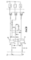
- Figs. 5 and 6 illustrate the basic electronic circuitry of the target.
- the reduction in resistance is detected by circuit 15 or 16 and the appropriate light A or B is illuminated and the siren operated.
- the light A or B is illuminated in each case for a period longer than that during which the siren sounds. While either light is on the circuit will not respond to either pressure pad. As a function check both lights are illuminated and the siren sounds when the power supply is switched on.
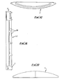
- Figs. 9-20 illustrate a third embodiment of a target.
- the base support poles consist of a pair of U-shaped metal poles which are resiliently biased into sockets on the base of the target.
- the U-shaped poles act as base supports and also define "no-go areas" during play.
- the poles are also designed to fold up around the sides and over the top of the post for transport and storage.
- This embodiment is similar to that shown in Figs. 7 and 8 but the post 4 has a modified upper area 7 which provides a neater construction.
- Fig. 21 illustrates a fourth embodiment of a target. This embodiment is similar to that shown in Figs. 9-20 but is of smaller overall dimensions. This embodiment is thus more easily portable than the previous embodiments.
- the base support poles also fold around the sides of the post 4 to form handles for ease of transportation.
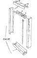
- Fig. 22 is an exploded perspective view illustrating a basic framework for a target. As can be seen the base 1, sides and upper area 7 are formed from steel channel sections to form a rigid framework for the target. The batteries 13 and electronic circuits 14 are also mounted on a similar steel channel section.
- Figs. 23-28 illustrate details of a further embodiment of a target.
- This target is identical in function to the earlier embodiments but differs in constructional details.
- the basic construction of this embodiment is similar to that illustrated in Fig. 22 with the base 1, sides and upper area 7 being formed from steel channel sections.
- the pressure sensitive pads 6A and 6B extend between the side sections.
- a number of alternative detecting means are possible. Examples of these are:
- the basic audible warning device may be supplemented or replaced by a bell, a whistle noise or a crowd cheering noise and the length of time for which the sound operates may be varied.
- the target may be produced in a variety of different sizes for different applications. Such different applications may require the use of different materials. For example various different plastics or combinations of metal and plastics may be used.
- the base may also be of plastics, metal or concrete as appropriate.
Abstract
Description
- This invention relates to apparatus for use in playing a game.
- According to the present invention there is provided apparatus for use in playing a game, comprising a ball and a target, the target having on its surface first and second mutually-distinguished areas each of which denotes an objective to be struck by the ball, the ball and target being used in accordance with rules hereinafter set forth.
- The target is preferably in the form of an upstanding post although other forms may also be used. The objective areas are preferably of equal size and disposed on equivalent portions of the target; for example they may be provided on opposite faces of the target at equal heights and of equal extent.
- The target may include indicator means for denoting when an objective area has been struck by the ball. Such indicator means may be visual or audible, an especially suitable form being one or more lights which are illuminated by switch means associated with the objective areas. Each objective area may be connected with a respective indicator means so that the objective area struck may be easily identified.
- The indicator means may include a pressure-sensitive actuator, for example a pad covering the entire objective area.
- Embodiments of the present invention will now be described by way of example with reference to the accompanying drawings in which:
- Fig. 1 is a perspective view of one embodiment of a target for use in the apparatus of this invention;
- Figs. 2, 3 and 4 are respectively a plan, side and front view of the target of Fig. 1;
- Fig. 5 is a schematic circuit diagram of a target;
- Fig. 6 is a circuit diagram of a scoring indicator circuit of a target;
- Fig. 7 is a perspective view showing two examples of a second embodiment of a target for use in the apparatus of this invention;
- Fig. 8 is a perspective view showing the construction of part of one of the targets of Fig. 7;
- Fig. 9 is a perspective view of a third embodiment of a target for use in the apparatus of this invention;
- Fig. 10 is a front view of the target of Fig. 9;
- Fig. 11 is a side view of the target of Fig. 10;
- Fig. 12 is a top plan view of the target of Fig. 10;
- Fig. 13 is a bottom plan view of the target of Fig. 10;
- Fig. 14 is a sectional view of the target of Fig. 10 taken along line A-A;
- Fig. 15 is a sectional view of the target of Fig. 10 taken along line B-B;
- Fig. 16 is a sectional view of the target of Fig. 10 taken along line C-C;
- Fig. 17 is a sectional view of the target of Fig. 10 taken along line D-D;
- Fig. 18 is a sectional view of the target of Fig. 10 taken along line E-E;
- Fig. 19 is a sectional view of the target of Fig. 10 taken along line F-F;
- Fig. 20 is a sectional view of the target of Fig. 10 taken along line G-G.
- Fig. 21 is a perspective view of a fourth embodiment of a target for use in the apparatus of this invention;
- Fig. 22 is an exploded perspective view showing constructional details of a target;
- Fig. 23 is a front view of a further embodiment of a target for use in the apparatus of this invention;
- Fig. 24 is a side view of the target of Fig. 23;
- Fig. 25 is a sectional side view of the target of Fig. 23 taken along C-C;
- Fig. 26 is a sectional plan view of the target of Fig. 23 taken along line D-D;
- Fig. 27 is a part cut away side sectional view to a different scale of the target of Fig. 23 taken along line A-A of Fig. 25; and
- Fig. 28 is a sectional detail view to a different scale of the target of Fig. 23 taken along line B-B of Fig. 27.
- Referring to Figs. 1 to 4 of the drawings, a first embodiment of a target comprises a
base 1 having acentral section 1A andside sections 1B which are hinged at 2 to the central section lA. Thebase 1 has anupward stub projection 3 which fits within a corresponding recess in a lower portion of anupright post 4. The post is of generally elliptical cross-section, and can be removed from thestub projection 3 and stored within a recess 5 in the underside of thebase 1, and enclosed therein by hingeing thesections 1B of the base so as to lie below the central section lA. - The opposed faces of the
post 4 are formed by pressure-sensitive pads pads upper area 7 of the post. Thelights - The
post 4 is 1.35m in height and the base is 1.05m in overall width and 1.25m in overall length. - A lightweight ball which actuates the pressure-
sensitive pads 4 on striking them is also provided, and the game is played as follows: - The game can be played by 2, 4, 6 or 8 people split into opposing sides. The game commences at the beginning and after each goal by bouncing the ball off at a point approximately 10 metres from the
post 4 along the midline of thepost 4. Opposing teams then play as in football with the object being to score goals by kicking the ball against an appropriate one of the pressure-sensitive pads - Referring to Figs. 7 and 8 of the drawings a second embodiment of a target is illustrated. This is similar to the embodiment described above but has smaller overall dimensions for ease of portability. In addition instead of a solid base the
post 4 is supported by poles, not shown, which are inserted intosockets 10 on thebase 1 of the target. A series of discs 11 mounted on runners 12 can be used as score indicators. The layout ofbatteries 13 andelectronic circuits 14 is illustrated in Fig. 8. - The overall height of the target is 0.95m with the height to the top of the pressure sensitive pads 0.85m and the width 0.64m. The base is 0.20m deep and the post 0.17m deep. The base support poles are formed from 30mm box section metal and are 0.85m long.
- The faces of the post forming the objective or target areas are each formed by 22 guage sheet metal each covered with a pair of security alarm pads. These pads comprise a foam layer with 10mm diameter holes cut out at approximately 20mm from each other. The foam layer is enclosed between two aluminium foil backed sheets attached to wires.
- This composite structure is enclosed in a sealed plastic envelope which leaves two wires extending.
- The pads are fixed to the post by double sided adhesive tape. The two sides are distinguished using coloured adhesive carpet backing tape.
- Figs. 5 and 6 illustrate the basic electronic circuitry of the target. When one side of the post is hit by the ball there is a reduction in resistance between the controls of the pad A or B (Fig. 6) on that side. The reduction in resistance is detected by
circuit 15 or 16 and the appropriate light A or B is illuminated and the siren operated. The light A or B is illuminated in each case for a period longer than that during which the siren sounds. While either light is on the circuit will not respond to either pressure pad. As a function check both lights are illuminated and the siren sounds when the power supply is switched on. - Figs. 9-20 illustrate a third embodiment of a target. In this embodiment the base support poles consist of a pair of U-shaped metal poles which are resiliently biased into sockets on the base of the target. The U-shaped poles act as base supports and also define "no-go areas" during play. The poles are also designed to fold up around the sides and over the top of the post for transport and storage.
- This embodiment is similar to that shown in Figs. 7 and 8 but the
post 4 has a modifiedupper area 7 which provides a neater construction. - Fig. 21 illustrates a fourth embodiment of a target. This embodiment is similar to that shown in Figs. 9-20 but is of smaller overall dimensions. This embodiment is thus more easily portable than the previous embodiments. The base support poles also fold around the sides of the
post 4 to form handles for ease of transportation. - Fig. 22 is an exploded perspective view illustrating a basic framework for a target. As can be seen the
base 1, sides andupper area 7 are formed from steel channel sections to form a rigid framework for the target. Thebatteries 13 andelectronic circuits 14 are also mounted on a similar steel channel section. - Figs. 23-28 illustrate details of a further embodiment of a target. This target is identical in function to the earlier embodiments but differs in constructional details. The basic construction of this embodiment is similar to that illustrated in Fig. 22 with the
base 1, sides andupper area 7 being formed from steel channel sections. - The pressure
sensitive pads - The embodiments illustrated are only by way of example.
- Various modifications and additional features are also envisaged.
- A number of alternative detecting means are possible. Examples of these are:
- Microphones;
- Vibration sensors;
- Trip wires placed over the target areas; Photo electric cells:
- Nets to trigger microswitches;
- Microswitches or magnetic reed switches
- triggered by initial ball contact on
- either face of the target;
- Various proximity switches including the
- use of a 'special' ball to trigger the
- mechanism; and
- Pneumatic 'air bag' switches.
- Various types of indicators can also be used. Examples of these are various types of
- Standard filament bulbs;
- Various gas filled bulbs;
- Mechanical shutters, black to luminous yellow/red, for example;
- No lights or colour indication at all, only noise;
- Variations in timing of flashes etc; and L.E.D./L.C.D. displays plus an automatic counter display.
- The basic audible warning device may be supplemented or replaced by a bell, a whistle noise or a crowd cheering noise and the length of time for which the sound operates may be varied.
- In addition to the embodiments described the target may be produced in a variety of different sizes for different applications. Such different applications may require the use of different materials. For example various different plastics or combinations of metal and plastics may be used.
- The base may also be of plastics, metal or concrete as appropriate.
Claims (9)
Priority Applications (1)
| Application Number | Priority Date | Filing Date | Title |
|---|---|---|---|
| AT85309400T ATE61739T1 (en) | 1984-12-28 | 1985-12-23 | DEVICE FOR PLAYING A GAME. |
Applications Claiming Priority (4)
| Application Number | Priority Date | Filing Date | Title |
|---|---|---|---|
| GB8432718 | 1984-12-28 | ||
| GB848432718A GB8432718D0 (en) | 1984-12-28 | 1984-12-28 | Apparatus for playing game |
| GB8526945 | 1985-11-01 | ||
| GB858526945A GB8526945D0 (en) | 1985-11-01 | 1985-11-01 | Apparatus for playing game |
Publications (3)
| Publication Number | Publication Date |
|---|---|
| EP0186486A2 true EP0186486A2 (en) | 1986-07-02 |
| EP0186486A3 EP0186486A3 (en) | 1987-08-26 |
| EP0186486B1 EP0186486B1 (en) | 1991-03-20 |
Family
ID=26288618
Family Applications (1)
| Application Number | Title | Priority Date | Filing Date |
|---|---|---|---|
| EP85309400A Expired - Lifetime EP0186486B1 (en) | 1984-12-28 | 1985-12-23 | Apparatus for use in playing a game |
Country Status (6)
| Country | Link |
|---|---|
| US (1) | US4676511A (en) |
| EP (1) | EP0186486B1 (en) |
| AU (1) | AU592326B2 (en) |
| DE (1) | DE3582232D1 (en) |
| ES (1) | ES296828Y (en) |
| PT (1) | PT81761B (en) |
Cited By (6)
| Publication number | Priority date | Publication date | Assignee | Title |
|---|---|---|---|---|
| NL9402058A (en) * | 1994-10-21 | 1996-06-03 | Cornelis Marie Lodewijks | Apparatus for methodical didactic help in improving skills |
| US6985939B2 (en) | 2001-09-19 | 2006-01-10 | International Business Machines Corporation | Building distributed software services as aggregations of other services |
| US7035944B2 (en) | 2001-09-19 | 2006-04-25 | International Business Machines Corporation | Programmatic management of software resources in a content framework environment |
| US7343428B2 (en) | 2001-09-19 | 2008-03-11 | International Business Machines Corporation | Dynamic, real-time integration of software resources through services of a content framework |
| US7603469B2 (en) | 2002-01-15 | 2009-10-13 | International Business Machines Corporation | Provisioning aggregated services in a distributed computing environment |
| US11130053B2 (en) | 2018-08-23 | 2021-09-28 | Rhenae Andre Thompson | Game contacting smart objects |
Families Citing this family (15)
| Publication number | Priority date | Publication date | Assignee | Title |
|---|---|---|---|---|
| AU599763B2 (en) * | 1987-03-09 | 1990-07-26 | Harry Fritz Boikowski | Improvements relating to sporting equipment |
| US5553860A (en) * | 1994-08-31 | 1996-09-10 | Zelikovich; Rami | Sports impact sensor apparatus for proximate operation |
| US5575478A (en) * | 1995-10-27 | 1996-11-19 | Catherine Lamberti | Gaming apparatus |
| FR2838355A1 (en) * | 2002-04-12 | 2003-10-17 | Didier Philippe Torres | Target for precision ball practice, e.g. with football, comprises assembled sections and two rigid panels with shock absorbing layer between |
| NO319643B1 (en) * | 2003-02-25 | 2005-09-05 | 2Feet | Ball game device |
| US7887467B2 (en) * | 2004-03-01 | 2011-02-15 | Bruce Wayne Booker | Whistling punching bag |
| GB0506297D0 (en) * | 2005-03-29 | 2005-05-04 | Nugent Richard J J | Sports apparatus |
| US8070965B2 (en) * | 2007-04-18 | 2011-12-06 | Tarves Robert J Jun | Dual walled dynamic phase separator |
| US20090291782A1 (en) * | 2008-05-20 | 2009-11-26 | Hinn Robert C | Soccer-golf games with electronic scoring and sensing system |
| US8663036B1 (en) | 2012-07-10 | 2014-03-04 | Alan Trieu | Adjustable ping pong table returning system |
| US8858372B1 (en) | 2012-07-10 | 2014-10-14 | Alan Trieu | Table tennis skill improvement racket |
| US9089751B1 (en) * | 2013-11-21 | 2015-07-28 | Iky A. Torres | Batting practice trainer |
| NO342252B1 (en) * | 2016-05-20 | 2018-04-30 | Roeynestad Tom Toralv | Exercise equipment for ball games |
| US20220062734A1 (en) * | 2020-08-26 | 2022-03-03 | P&P Imports LLC | Column configuration for sporting equipment |
| USD1005396S1 (en) | 2022-01-20 | 2023-11-21 | Christian Bendyna | Throwing game board apparatus |
Citations (5)
| Publication number | Priority date | Publication date | Assignee | Title |
|---|---|---|---|---|
| US3580575A (en) * | 1967-08-28 | 1971-05-25 | Autotelic Ind Ltd | Game device including selectively impact operable lights |
| US4199141A (en) * | 1978-03-27 | 1980-04-22 | Garcia Abril I | Baseball pitching scoring apparatus |
| US4261570A (en) * | 1979-09-06 | 1981-04-14 | Switzer William K | Field surface related projectile target construction |
| SU917845A1 (en) * | 1979-07-24 | 1982-04-07 | Всесоюзный Проектно-Технологический Экспериментально-Конструкторский Институт По Спортивным И Туристским Изделиям | System for monitoring throwing at target |
| SU978880A1 (en) * | 1981-02-02 | 1982-12-07 | Рижский Краснознаменный Институт Инженеров Гражданской Авиации Им.Ленинского Комсомола | Apparatus for training with ball |
Family Cites Families (3)
| Publication number | Priority date | Publication date | Assignee | Title |
|---|---|---|---|---|
| US2783999A (en) * | 1954-02-25 | 1957-03-05 | Reflectone Corp | Golf game |
| US3117783A (en) * | 1962-05-17 | 1964-01-14 | Willard J Reid | Game apparatus |
| US4232866A (en) * | 1978-10-02 | 1980-11-11 | Attilio Pennachio | Apparatus for playing a game of chance |
-
1985
- 1985-12-23 DE DE8585309400T patent/DE3582232D1/en not_active Expired - Lifetime
- 1985-12-23 EP EP85309400A patent/EP0186486B1/en not_active Expired - Lifetime
- 1985-12-23 US US06/812,221 patent/US4676511A/en not_active Expired - Fee Related
- 1985-12-24 AU AU51691/85A patent/AU592326B2/en not_active Ceased
- 1985-12-26 PT PT81761A patent/PT81761B/en not_active IP Right Cessation
- 1985-12-27 ES ES1985296828U patent/ES296828Y/en not_active Expired
Patent Citations (5)
| Publication number | Priority date | Publication date | Assignee | Title |
|---|---|---|---|---|
| US3580575A (en) * | 1967-08-28 | 1971-05-25 | Autotelic Ind Ltd | Game device including selectively impact operable lights |
| US4199141A (en) * | 1978-03-27 | 1980-04-22 | Garcia Abril I | Baseball pitching scoring apparatus |
| SU917845A1 (en) * | 1979-07-24 | 1982-04-07 | Всесоюзный Проектно-Технологический Экспериментально-Конструкторский Институт По Спортивным И Туристским Изделиям | System for monitoring throwing at target |
| US4261570A (en) * | 1979-09-06 | 1981-04-14 | Switzer William K | Field surface related projectile target construction |
| SU978880A1 (en) * | 1981-02-02 | 1982-12-07 | Рижский Краснознаменный Институт Инженеров Гражданской Авиации Им.Ленинского Комсомола | Apparatus for training with ball |
Non-Patent Citations (2)
| Title |
|---|
| SOVIET INVENTIONS ILLUSTRATED, Section Mechanical, 16th March 1983, Week K05, abstract no. B6789 W04, Derwent Publications Ltd., London, GB; & SU - A - 917 845 (SPORT TOURISM INST) 07-04-1982 * |
| SOVIET INVENTIONS ILLUSTRATED, Section Mechanical, 23rd November 1983, Week K41, abstract no. 787290 P36, Derwent Publications Ltd., London, GB; & SU - A - 978 880 (RIGA CIVIL AVIAT ENGS) 07-12-1982 * |
Cited By (6)
| Publication number | Priority date | Publication date | Assignee | Title |
|---|---|---|---|---|
| NL9402058A (en) * | 1994-10-21 | 1996-06-03 | Cornelis Marie Lodewijks | Apparatus for methodical didactic help in improving skills |
| US6985939B2 (en) | 2001-09-19 | 2006-01-10 | International Business Machines Corporation | Building distributed software services as aggregations of other services |
| US7035944B2 (en) | 2001-09-19 | 2006-04-25 | International Business Machines Corporation | Programmatic management of software resources in a content framework environment |
| US7343428B2 (en) | 2001-09-19 | 2008-03-11 | International Business Machines Corporation | Dynamic, real-time integration of software resources through services of a content framework |
| US7603469B2 (en) | 2002-01-15 | 2009-10-13 | International Business Machines Corporation | Provisioning aggregated services in a distributed computing environment |
| US11130053B2 (en) | 2018-08-23 | 2021-09-28 | Rhenae Andre Thompson | Game contacting smart objects |
Also Published As
| Publication number | Publication date |
|---|---|
| US4676511A (en) | 1987-06-30 |
| AU592326B2 (en) | 1990-01-11 |
| ES296828Y (en) | 1988-09-16 |
| PT81761B (en) | 1987-10-20 |
| ES296828U (en) | 1988-01-16 |
| EP0186486A3 (en) | 1987-08-26 |
| AU5169185A (en) | 1986-07-03 |
| EP0186486B1 (en) | 1991-03-20 |
| PT81761A (en) | 1986-01-02 |
| DE3582232D1 (en) | 1991-04-25 |
Similar Documents
| Publication | Publication Date | Title |
|---|---|---|
| EP0186486A2 (en) | Apparatus for use in playing a game | |
| US4199141A (en) | Baseball pitching scoring apparatus | |
| US4765622A (en) | Hockey game | |
| US5615880A (en) | Electronic goal detecting system | |
| US4830369A (en) | Baseball pitching practice target | |
| AU6345286A (en) | Transducer arrangement for detecting and indicating a scoring hit in sports games such as karate and fencing | |
| US9220967B2 (en) | Method of providing a tennis practice target and display | |
| WO2005110555A2 (en) | Ball with internal impact detector and an indicator to indicate impact | |
| US5988646A (en) | Impact sensor and target apparatus embodying the same | |
| US20160213989A1 (en) | Ball game and apparatus | |
| US6394903B1 (en) | Toy dice | |
| US5356135A (en) | Combination hockey & roller ball reflex practice board | |
| KR950031139A (en) | Golf practice | |
| US5069450A (en) | Automatic umpire for slow pitch softball | |
| US5449326A (en) | Bumper bowling system with contact switch | |
| US3254433A (en) | Scoring device | |
| US5316296A (en) | Shock-absorbing game racket | |
| GB2271724A (en) | Board game apparatus. | |
| US11376490B2 (en) | Game scoring and tracking system | |
| JPS61222468A (en) | Apparatus used in game | |
| WO2005028035A1 (en) | Ball and game | |
| US3215434A (en) | Bowling practice game device | |
| ATE9271T1 (en) | BAT. | |
| JPS642775Y2 (en) | ||
| AU718054B2 (en) | A football game apparatus |
Legal Events
| Date | Code | Title | Description |
|---|---|---|---|
| PUAI | Public reference made under article 153(3) epc to a published international application that has entered the european phase |
Free format text: ORIGINAL CODE: 0009012 |
|
| AK | Designated contracting states |
Kind code of ref document: A2 Designated state(s): AT BE CH DE FR GB IT LI NL SE |
|
| PUAL | Search report despatched |
Free format text: ORIGINAL CODE: 0009013 |
|
| AK | Designated contracting states |
Kind code of ref document: A3 Designated state(s): AT BE CH DE FR GB IT LI NL SE |
|
| 17P | Request for examination filed |
Effective date: 19880226 |
|
| 17Q | First examination report despatched |
Effective date: 19890123 |
|
| GRAA | (expected) grant |
Free format text: ORIGINAL CODE: 0009210 |
|
| AK | Designated contracting states |
Kind code of ref document: B1 Designated state(s): AT BE CH DE FR GB IT LI NL SE |
|
| PG25 | Lapsed in a contracting state [announced via postgrant information from national office to epo] |
Ref country code: SE Effective date: 19910320 Ref country code: NL Effective date: 19910320 Ref country code: LI Effective date: 19910320 Ref country code: IT Free format text: LAPSE BECAUSE OF FAILURE TO SUBMIT A TRANSLATION OF THE DESCRIPTION OR TO PAY THE FEE WITHIN THE PRESCRIBED TIME-LIMIT;WARNING: LAPSES OF ITALIAN PATENTS WITH EFFECTIVE DATE BEFORE 2007 MAY HAVE OCCURRED AT ANY TIME BEFORE 2007. THE CORRECT EFFECTIVE DATE MAY BE DIFFERENT FROM THE ONE RECORDED. Effective date: 19910320 Ref country code: CH Effective date: 19910320 Ref country code: AT Effective date: 19910320 |
|
| REF | Corresponds to: |
Ref document number: 61739 Country of ref document: AT Date of ref document: 19910415 Kind code of ref document: T |
|
| REF | Corresponds to: |
Ref document number: 3582232 Country of ref document: DE Date of ref document: 19910425 |
|
| REG | Reference to a national code |
Ref country code: CH Ref legal event code: PL |
|
| ET | Fr: translation filed | ||
| NLV1 | Nl: lapsed or annulled due to failure to fulfill the requirements of art. 29p and 29m of the patents act | ||
| PLBE | No opposition filed within time limit |
Free format text: ORIGINAL CODE: 0009261 |
|
| STAA | Information on the status of an ep patent application or granted ep patent |
Free format text: STATUS: NO OPPOSITION FILED WITHIN TIME LIMIT |
|
| 26N | No opposition filed | ||
| PGFP | Annual fee paid to national office [announced via postgrant information from national office to epo] |
Ref country code: BE Payment date: 19920630 Year of fee payment: 7 |
|
| PG25 | Lapsed in a contracting state [announced via postgrant information from national office to epo] |
Ref country code: BE Effective date: 19921231 |
|
| BERE | Be: lapsed |
Owner name: MACKIE DONALD ELRICK Effective date: 19921231 |
|
| PGFP | Annual fee paid to national office [announced via postgrant information from national office to epo] |
Ref country code: GB Payment date: 19931223 Year of fee payment: 9 |
|
| PGFP | Annual fee paid to national office [announced via postgrant information from national office to epo] |
Ref country code: FR Payment date: 19931227 Year of fee payment: 9 |
|
| PGFP | Annual fee paid to national office [announced via postgrant information from national office to epo] |
Ref country code: DE Payment date: 19940225 Year of fee payment: 9 |
|
| PG25 | Lapsed in a contracting state [announced via postgrant information from national office to epo] |
Ref country code: GB Effective date: 19941223 |
|
| GBPC | Gb: european patent ceased through non-payment of renewal fee |
Effective date: 19941223 |
|
| PG25 | Lapsed in a contracting state [announced via postgrant information from national office to epo] |
Ref country code: FR Effective date: 19950831 |
|
| PG25 | Lapsed in a contracting state [announced via postgrant information from national office to epo] |
Ref country code: DE Effective date: 19950901 |
|
| REG | Reference to a national code |
Ref country code: FR Ref legal event code: ST |