EP0181438B1 - Host-programmable input/output terminal - Google Patents
Host-programmable input/output terminal Download PDFInfo
- Publication number
- EP0181438B1 EP0181438B1 EP85109734A EP85109734A EP0181438B1 EP 0181438 B1 EP0181438 B1 EP 0181438B1 EP 85109734 A EP85109734 A EP 85109734A EP 85109734 A EP85109734 A EP 85109734A EP 0181438 B1 EP0181438 B1 EP 0181438B1
- Authority
- EP
- European Patent Office
- Prior art keywords
- data
- designating
- input
- entry
- designated
- Prior art date
- Legal status (The legal status is an assumption and is not a legal conclusion. Google has not performed a legal analysis and makes no representation as to the accuracy of the status listed.)
- Expired - Lifetime
Links
Images


Classifications
-
- G—PHYSICS
- G06—COMPUTING; CALCULATING OR COUNTING
- G06F—ELECTRIC DIGITAL DATA PROCESSING
- G06F3/00—Input arrangements for transferring data to be processed into a form capable of being handled by the computer; Output arrangements for transferring data from processing unit to output unit, e.g. interface arrangements
- G06F3/01—Input arrangements or combined input and output arrangements for interaction between user and computer
- G06F3/048—Interaction techniques based on graphical user interfaces [GUI]
- G06F3/0487—Interaction techniques based on graphical user interfaces [GUI] using specific features provided by the input device, e.g. functions controlled by the rotation of a mouse with dual sensing arrangements, or of the nature of the input device, e.g. tap gestures based on pressure sensed by a digitiser
- G06F3/0489—Interaction techniques based on graphical user interfaces [GUI] using specific features provided by the input device, e.g. functions controlled by the rotation of a mouse with dual sensing arrangements, or of the nature of the input device, e.g. tap gestures based on pressure sensed by a digitiser using dedicated keyboard keys or combinations thereof
Definitions
- the present invention relates to a data input/output terminal equipment which is connected to a host machine (host-computer) communicably wherein at least one program stored in the host machine is loaded prior to data input/output and data are input and/or output under the control of the program loaded.
- host machine host-computer
- the conventional data input/output terminal equipment is developed only for an exclusive use in which application programs thereof are so designated as to be adapted for a specified category of business and for business usage therein.
- application programs have to be designed according to every specified category of business such as a transportation service, a wholesale business etc. and, even in the same specified category of business, according to every service such as receipt service of goods, shipping service of goods etc. Accordingly, even in the same category of business, a variety of terminal equipments are provided each for every service thereof. This causes increase in number of the equipments and leads to possible misuse among them and a lower utility thereof.
- a data input/output terminal equipment connected to a host computer is known.
- the known equipment is designed for an emergency medical care information system comprising a clinical computer network through which a plurality of such equipments placed at clinical institutes are connected to the control-center host computer.
- the host computer collects data relating e.g. to the waiting status of doctors in charge for each department so that the system can give directions for taking an acutely ill patient to an appropriate hospital as quickly as possible.
- the user can communicate with the system according to a plurality of application programs registered in the system. For each service a separate application program is required to load in the data input/output terminal equipment. Thus, kind and number of the application programs are limited to those registered beforehand.
- the data input/output equipment comprises:
- Fig. 1 and 2 show a block diagram of the system and construction of the data input/output terminal equipment, and Fig. 3 shows a front view of the equipment.
- the data input/output equipment EOST communicably is connected to a host machine HM and comprises a mode setting means A for designating at least a program setting mode and an execution mode, a RAM means B for storing at least one basical program being loaded from the host machine, a parameter setting means C for designating parameters included in the basical program loaded in the program setting mode to define a plurality of applcation programs, each of which is available for a specified service, a RAM means T for memorizing parameters designated, a RAM means E for memorizing entry data, and a service selecting means F for designating one of application programs in the execution mode.
- a mode setting means A for designating at least a program setting mode and an execution mode
- a RAM means B for storing at least one basical program being loaded from the host machine
- a parameter setting means C for designating parameters included in the basical program loaded in the program setting mode to define a plurality of applcation programs, each of which is available for a specified service
- a RAM means T for memorizing parameters
- the present data terminal is comprised of a central processing unit (hereinafter referred to CPU 1) being composed of one-chip micro - processor;
- One more RAM 17 for programs and a pen reader 18 for reading bar codes (hereinafter referred to TPR 18) can be equipped as optional equipment.
- CPU 1 is connected via serial interface 12 and/or parallel interface 13, to a host computer 19 and/or another data input/output terminal equipment 20.
- the mode switch 9 is a slide switch for selecting either one of modes A and B.
- PRAM 3 and DRAM 4 are always backed up by a battery means (not shown) stored in the equipment.
- the first and second system switches 7 and 8 are arranged operably in the battery chamber 21 each of which is a switch having three selectable positions A, B and C. The first and second system switches 7 and 8 are used for designating a specified mode together with the mode switch 9.
- Figs. 5 and 6 show a flow chart of main routine being proceeded by CPU 1.
- the system is initialized first and is checked whether programs have been loaded or not and whether they are normal or not. Then, the voltage of the battery is checked. When the battery is normal, the mode to be proceeded by CPU 1 is identified. The mode is designated by a combination of the first and second system switches 7 and 8 and the mode switch 9, as is shown in Table 1.
- the mode for testing hardwares such as ROM, RAM, the liquid crystal display, the key board and the buzzer by proceeding a diagnosis program stored in ROM 2.
- the application mode is divided into parameter setting mode and execution mode.
- the mode for designating specifications with respect to each of services such as data entry services (maximum seven kinds can be set), data output service (one kind), data input service (one kind), data collection service (one kind as an optional service) through setting or designating parameters.
- the mode for executing each service program mentioned above according to operations necessary for initial setting, initial registration and selection of service such as data entry services, data output service and so on.
- the mode for loading programs and parameters into PRAM 3 and DRAM 4 which are transmitted from the host machine and/or other data terminal equipment.
- the mode for unloading programs and parameters having been stored in PRAM 3 and DRAM 4 to the host machine and/or other data terminal equipment.
- the program setting mode is the most characteristic mode according to the present invention.
- each service program can be made through setting parameters as will become apparent hereinafter.
- the present equipment is applicable for each of a variety of categories of business commonly, since a plurality of service programs can be made most appropriately according to the category of business taking user's requirements into considerations.
- Fig. 7 The key arrangement for this mode is shown in Fig. 7. This key arrangement is fixed in the mode. In the arrangement, keys to be operated are ten keys "0" to "9", six alphabetic keys “A” to “F”, three function keys “FK1 " to "FK3” and a clear key "CE”.
- the operation NK1 is a key operation for designating a job number JOB# (for instance, of 4 digits)
- the operation NK2 is a key operation for designating an item number ITEM# (for instance, of 2 digits)
- the operation NK3 is a key operation for designating data for setting parameters which are predetermined according to every parameter to be set.
- Function key FK1 transfers the key operation from NK1 to NK2 upon the first and push down thereof and effect to display the content of the job being designated by JOB# upon the second push down thereof.
- Function key FK2 transfers the key operation automatically to a next key operation for designating ITEM# or JOB# upon every push down thereof.
- Function key FK3 effects to display the content of the next job upon the push down thereof.
- function key FK3 is pushed down successively.
- Fig. 9 shows the data format for the memory for registering data being used for data entry during the execution mode.
- the initial registration record and service code record are fixed after having been set once according to the system. Each of heading, detail and footing records is fixed with respect to each data entry service selected. The initial registration, service code, heading and footing records may be not necessarily set.
- Each record except for the service code record is comprised of a plurality of items (fields) as is shown in Fig. 10.
- the heading record is provided for memorizing heading data such as a sum of individual quantity as for the quantity, a sum of individual amount of money as for the amount of money, date and time upon inputting and/or outputting data or the like.
- Parameters for setting the heading record can be designated through JOB# "0101 " to "0114” and ITEM# "10" to "14".
- Table 2 shows the manner for designating parameters of the heading record.
- Detail record is defined for memorizing particular data such as a unit price of an individual article, and/or a quantity thereof.
- the manner for designating parameters of the detail record is shown in Tables 3-1 and 3-2.
- the footing record is provided for finishing or completing detail records in such a manner as to memorize, for instance the total amount of money summed up all through detail records which is defined at a position next to the final detail record.
- the manner for designating parameters of the footing record is shown in Table 4.
- Each length (number of digits) necessary for every item is designated by one of integers "01 “ to "15”.
- C/D check codes, symbols such as decimal point ".”, signs " ⁇ ” etc. and item partition code are included in calculation of the number of digits.
- the length of each item designated is assigned to the memory for registering data.
- the number of line on which the data is displayed, the beginning digit on the line from which the data is displayed and the length of digits are designated respectively.
- item partition code is to be memorized or not upon memorizing each item in the memory for registering data.
- the code is designated with one of numerals or alphabets shown in Table 2. It is to be noted that the codes in the case of 4 BIT is differentiated from those in the case of 8 BIT.
- a key code is designated with a number of two digits to indicate that the input of the final item has been completed. When the key code designated is input, all inputs regarding the item is supposed to be finished.
- the present system provides two calendar functions. One is a function being able to write the calendar into the initial registration item and the other is a function being able to read the calendar of the item in the heading or detail record. It can be designated whether the calendar function is necessary or not. When the calendar function is designated, one of three types of the calendar "date”, "time” and “date and time” is specified.
- the content of the calendar is checked by inequalities such as 00 ⁇ hours ⁇ 23, 00 ⁇ minutes ⁇ 59.
- the extent check is provided for checking whether the data input; for instance the amount of the money, is within the extent defined between an upper and lower limits or not.
- One combination can be designated among many, for instance ten combinations with respect to the upper limit and the lower limit which are defined as in the Table 5. If the calendar check is not designated with respect to one item, multiple extent checks (maximum 5 checks) become possible. Upon multiple extent checks, every check is done with use of "OR" logic and , in every check, only a significant number except for signs and the decimal point is checked.
- FIG. 11 shows a method for assigning weights when five numbers ni , n 2 , n 3 , n 4 and n 5 are designated as weights therefor.
- C/D check can be specified in Table 6 as a C/D check, table in which maximum six kinds of C/D check can be defined. Parameters to be designated are the number of C/D check table, whether or not other item is added to, and, if other item is to be added, the number of other item.
- comparison check data input are compared with data having been memorized in the memory for initial setting. As the result of the comparison, data input is processed duly when both data correspond to each other. When no correspondence between both data is obtained, an error message is displayed.
- This check is an equal check for checking whether the total value obtained through items in the heading or the detail records is equal to the value obtained by a totalizer provided in this system.
- Fig. 12 shows an example of the sum check.
- total number of clients obtained in the system totalizer by adding each number of clients being input into items of ITEM#1 to 3 respectively is compared with the total number of clients input into the item of ITEM#5.
- the sum check is available to both of the heading and detail records.
- One of numbers of the system totalizer "01 " to "04" is designated for the sum check.
- the total value (sum value) is cleared when the sum check has been finished.
- the system totalizer will be more fully disclosed in section (c) entitled "Use of System Totalizer".
- Fig. 13 shows a composition of the master file.
- a line number, top digit number and a number of digits for the display of each item are designated. If the line number is designated to "0", the corresponding item is not displayed.
- the position, length and editorial type for the display with respect to each item of the master data are designated according to Table 9 and Table 10.
- the input data (of a positive integer) is edited in the manner same to that of memory format and detail records of the data registration memory are searched, from the top thereof, with the key obtained as the result of the edition mentioned above.
- Editorial method for the display is as follows:
- Memory editorial method about the heading record, the detail record and the footing record are different from each other in designating method about parameters.
- the memory editorial method for the detail record will be explained particularly.
- the position of a decimal point on the memory is designated by one of integers "00", “01 and "02" (When "00" is designated, any decimal point is not assigned on the memory).
- Data input is edited referring to the position of the decimal point designated as a standard therefor. In this case, the portion overflowed from the memory area is cut off and blank portion of the area is filled with zeros.
- data are edited referring to the most right-hand position of the area as a standard. It depends on the designation of the system parameter whether the position of the decimal point is memorized or not.
- the input data is coupled or synthesized with the input data of other item of the heading record and/or the detail record.
- code "30" is first designated and the item number of the item to be synthesized (or coupled) is designated.
- totalizers 14 digits of the integer portion and two digits of the decimal fraction.
- the sum data of individual value to be input into individual item of the detail record is input first into the item #n of the heading record and the sum data is saved into a system totalizer upon the input thereof. Thereafter, individual data is input into individual item (#I to #n) of the detail record. These individual data are added in other system totalizer. In this case, the sum data having been saved is compared with the sum obtained in the other system totalizer in order for equal check.
- One fashion is set for the heading record or the footing record.
- the total number of digits is that of a significant number of the data and therefore, does not include the decimal point ".” and " ⁇ " signs and the like.
- Input Data are flushed to the right and all of blank digits are filled with zeros.
- Input data are flushed to the left, all of blank digits are filled with one of filler codes (HEX"0" - "9").
- Fig. 14 shows an example of data synthesis with respect to the item #2.
- the article code input into lower five digits at this time is synthesized with the classification code having been input into heading three digits of the preceding record.
- the top digit P of the data to be replaced with a new data is designated according to the key input fashion as is disclosed in ITEM#11.
- the synthesized data (classification code + article code) is input into the item #2 of the present pending record.
- the data synthesis method as mentioned above is able to simplify entry operation in such a case that all data have a portion common to each other.
- Fig. 15 shows a flow chart for data synthesizing upon data entry in the execution mode.
- the data synthesized is displayed so as to be confirmed it at step 104.
- step 105 a variety of checks are made as stated hereinafter. When all of checks are cleared, memory edition is executed and data are saved in the Write Buffer. These processes are repeated until the data entry of the last item have been completed (step 107).
- the data thus input and or synthesized are memorized in DRAM at step 108 and, then, data entry for the next record is started.
- the entry fashion is designated in ITEM#14. If data input is finished after a plurality of scannings of TPR, the entry fashion is designated in ITEM#15.
- C/D check method In order to prevent errors upon reading bar codes, data having been read are checked by C/D check method. In the case that data is input by ten keys, C/D check is done in order to prevent deposition mistakes similarly. However, the C/D check is available only for integers. Accordingly, it is impossible to do C/D check about data including symbols such as a decimal point, " ⁇ " signs etc.
- Fig. 17 shows a flow chart for C/D check.
- a real number for examp!e "-1234.67” is input from TPR at step 102
- " • sign and ".” decimal point in the input data are replaced respectively to decimal values designated, for example "11” and "31”, at step 104.
- C/D value is calculated with respect to the number obtained as the result of the replacement, for example "1112343167", at step 105.
- the result thus obtained is compared with C/D value. If the former is not equal to the latter, "Error" is indicated on the display. This idea is applicable to data including the symbols " ⁇ ", "S” and the like, indicating the currency of individual country.
- the terminal equipment according to the present invention is able to provide a variety of functions selectively in addition to those functions as are disclosed in the foregoing.
- the present system is characterized in that a plurality of service programs can be made through designation of system parameters and can be executed according to system parameters designated. Therefore, system parameters are required a very high reliability substan - tially equal to that of programs.
- check about system parameters can be possible as well as the check about programs in order to avoid mal-functions.
- the check about parameters are executed after the program routine has been completed and the power switch was turned off.
- Power-OFF Routine POR is executed for checking parameters having been set during program setting mode.
- check code such as Check Sum Code is calculated above the memory area in which parameters having been set are memorized and check code obtained has been set at a predetermined memory area.
- each parameter is checked in the Parameter Setting Mode, for instance by comparing each parameter being displayed with that in the data setting table.
- the master filing function according to the present system is comprised of a series of functions as follows:
- Master file is defined as an assembly of records having a predetermined same length, as is shown in Fig. 18, which has a numeral data indicating the beginning digit of the first record thereof as the top data.
- Each record thereof contains, as shown in Fig. 19, a top data indicating the beginning digit of a key data Mkey and the key data MKey through which the master file is searched.
- the master file is set according to the Tables 13 and 14.
- Each record is comprised of ten items from the first to tenth item.
- the length and beginning digit are designated according to tables mentioned above.
- Formats for displaying master data as references are set by designating a display line li, beginning digit di and digit length mi of each item i at the item #21 in JOB#4301 of Table 13. Further, editorial method for display is designated according to Table 15. Fig. 20 shows an example of the display.
- the master file of the terminal equipment is made by reading the corresponding caster file of the host machine serially or parallelly.
- Fig. 21 shows a flow chart showing a manner for data entry using master files.
- the present terminal equipment is connected to the host machine with the serial or parallel receiving cable.
- the master file of the host machine is read out and is memorized in the memory area of the terminal equipment reserved therefor to construct the master file therein.
- the master file can be made with respect to each service such as an ordering service, stock management or the like.
- the master file having been made can be corrected manually monitoring data thereof.
- the master data search check is executed as follows. This check, however, can be done only when the master data search check code is designated to "6000" at item #11 for designating check method of the Table 3 - -1.
- the check can be done in two modes C I and C 11 as shown in Fig. 21.
- the key data MKey through which the master data is searched is designated at the step 401.
- the mode switch is operated to set mode and the check is executed according to the flow chart shown in Fig. 22.
- step 501 When data of one record were input at step 501, one of function keys FK is operated. At step 502, it is decided if the search check for the master data should be done or not and, when the check is to be done, it is made by searching about each record whether or not the key data MKey of the record of the master file is correspond to the key data R key having been entered.
- the record having the MKey is displayed according to the display format mentioned above. Referring to the content displayed, data for other item are entered. When the entry operation for one record is finished, data for next record are entered and the search check is done therefor.
- the first record of the master file is displayed at step 406 in Fig. 21.
- the feed-forward function key is pushed and the second record is displayed.
- records of the master file are monitored successively.
- a predetermined function key FK is pushed at step 407
- the key data MKey of the corresponding record of the master file is read at step 408 and is memorized as the corresponding item of the entry data.
- data for other item are entered referring to the data displayed at step 409.
- data of other item of the record in the master file can be memorized as they are, similarly to the case of the key data.
- Data being treated in the terminal equipment can be integers and/or real numbers.
- the data is a real number, it may be a data having a decimal point of a variable digit or of a fixed digit.
- data of an integer or of a real number of a fixed digit is not necessary to memorize the decimal point itself although it should be memorized with respect to the data of a real number of a variable decimal point.
- the necessity of memorizing a decimal data depends on conditions under which data are processed.
- the volume of memory can be reduced when compared with the case in that every data about the decimal point is memorized without any exception.
- Fig. 23 shows a flow chart therefor. As shown in Fig. 23, when the data entry job is selected at step 101, application program corresponding to the data entry job is called at step 102, and data are entered with use of ten keys (at step 103) or through TPR (at step 104).
- step 105 it is decided if data should be memorized dependent upon the position of a decimal point.
- input data are edited according to the editorial method designated ("Flush Right” or “Flush Left” etc. ) and are memorized.
- step 109 it is decided if the data about the decimal point should be memorized or not at step 107, and, in the case of "YES", the data are memorized with decimal point respectively at step 108. In the case of "NO”, data are memorized without the decimal point even when it is included therein (step 109).
- step 110 After the data are memorized at one of steps 106, 108 or 109, it is decided if data entry is finished at step 110. If it is not finished, data are entered further at step 103 or 104. When the data entry operation is completed, there transferred to other operations.
- an essential object of the function is as follows.
- the quantity of an article to be ordered is specified with a unit such as one dozen, one carton or the like which is usually determined depending on the property of the article and the store in which the article is dealt with. Also, there are many zeros in data with respect to the quantity in the stock management.
- entry operations such as ten key "1 • _ function key - ten key "0" function key are repeated usually. In such a case as mentioned above, entry operations will be much simplified if a number of "0" or "1 " is automatically input only by pushing a function key without a deposition with use of a ten key.
- Fig. 24 shows a flow chart therefor. As is shown in Fig. 24, when one of data entry jobs is chosen, data are entered with use of ten keys or through TPR and, then, a function key is operated usually. Instead of the usual data entry, a specified function key can be operated first without the operations of one or more ten keys.
- Such omission of deposit is designated about every item of entry data. Therefore, it becomes possible to use the same function key as a key for omission of deposit among a variety of data entry jobs commonly. Accordingly, it becomes unnecessary to increase the number of function keys, key operations can be simplified, the entry speed can be made fast and possible entry mistakes can be avoided.
- the data of the corresponding item of the preceding record is automatically memorized as that of the present record when the skip of the data entry is made.
- the setting conditions about the skip is possible by designating parameters at the item #01 in Table 3-1.
- Fig. 25 shows a flow chart for skipping data entry.
- step 101 when each item is input by ten keys or through TPR, it is decided at step 101, if the entry fashion corresponds to that designated about the item (See items #13 and #14 in Table 2). In the case of "NO”, it is decided if the skip of data entry is possible at step 102. In the case of "YES”, it is decided if the entry fashion corresponds to that of the next item at step 103. Namely, at this step 103, it is decided if the data entry with respect to the item next to the item to be skipped was done. In the case of "NO", it is required to re-enter the data.
- step 105 the data of the item skipped having been edited is set in the buffer memory as the input data. Alternatively, if the entry fashion corresponding to that designated at step 101, there proceeded directly to step 105.
- step 106 When the entry about all items of one record is completed (step 106), the entry data in the buffer memory is set in the data memory as one record at step 107 and, then, the data entry for the next record is done.
- the entry of the common data can be skipped to execute the next data entry. Therefore, the data entry operation is simplified and can be done fast and possible entry errors can be avoided.
- the service identification code representing the kind thereof is automatically written on the data memory.
- the code is written at the timing that a job key for data entry is pushed down.
- the code is provided for identifying the kind of data in the case that the host machine accesses data entered at the side of the data terminal equipment and process data accessed.
- the digit length and content of the service identification code are set in the setting mode.
- the service identification code should be written on the data memory upon the data entry or not.
- the digit number can be designated arbitrarily.
- the content thereof can be also designated arbitrarily within the digit number designated for every data entry job (See Tables 19 and 20).
- the service identification code is set by designating a code suitable for representing the content of the service briefly within the digit number designated.
- Fig. 26 shows a flow chart for processing the service identification code.
- step 101 when one of data entry jobs is chosen at step 101, it is decided whether the service identification code is designated or not at step 102. In the case that it is designated, it is set in the data memory at step 103. Therefore, the service identification code is automatically assigned to the head of each data being entered in this data entry job.
- step 104 data regarding to the data entry job are entered sequentially and data having been entered are set by one record unit in the data memory. The data entry is continued until the completion of the data entry is confirmed at step 105.
- step 103 is skipped and the data entry at step 104 is executed.
- the next job for instance the output of data to the host machine is started.
- the data output job is chosen at step 106, the entry data memorized in the data memory are output to the host machine at step 107. Since the service identification code is output at first as a heading data upon the data output if it is designated, the kind of service with respect to data being input can be easily identified at the side of the host machine and, therefore, the sort or arrangement of data can be done advantageously.
- the memory clear job is designated at step 108 and the data in the data memory are cleared at step 109.
- the extent and/or the line to be scrolled up should be varied according to the display format.
- the scroll up function according to the present system is improved so as to be available for an arbitrary display format by changing parameters related thereto.
- Fig. 27 shows an example of the display of the entry data for the ordering service in which the scroll up function is not designated and Fig. 28 shows an example of the display of the entry data for the stock management in which each data entered is scrolled up in turn.
- a set of guide texts such as "ORDERING SERVICE”, “ARTICLE CODE”, “A DAY OF THE WEEK”, “CLASSIFICATION”, “UNIT PRICE” and “QUANTITY” are displayed in a fixed manner.
- Data are entered in the order of the article code D i , a day of the week D 2 , the classification D 3 , the unit price D 4 and the quantity D s .
- all these data D 1 to D 5 are cleared up on the display.
- Data are entered in the order of the article code Dn, unit price Dm and quantity DI.
- the set of these data Dn, Dm and DI is displayed on the lowermost line (the eighth line).
- the set of data D n - 1 , D m - 1 and D I - 1 entered prior to the set of Dn, Dm and DI is scrolled up from the eighth line to the seventh line.
- each proceeding set of data ((D n - 2 , D m - 2 , Di-z), - - (Dn-4, D m - 4 , D l-4 )) is scrolled up by one line on the display.
- This scroll up function is designated in the program setting mode and is effected in the execution mode.
- Fig. 29 shows a flow chart for program setting and Fig. 30 shows a flow chart far effecting the scroll up function.
- the mode is the execution mode or not at step 101.
- one job number "4301 " is designated among jobs (JOB#4301 to 4307) for designating a fashion of the scroll up at step 102.
- n i is the parameter for designating the number of lines by which the data is scrolled up
- n 2 is the parameter for designating the line number which defines the upper limit of the area being able to scroll up
- n 3 is the parameter for designating the line number which defines the lower limit of the area.
- the parameters ni, n 2 and n 3 are set equal to "1 ", "4" and "8" respectively.
- each of parameters ni, n 2 and n 3 is checked whether it is within the allowable extent for scroll up or not (In the example shown, the maximum of each parameter is set equal to 8).
- the parameter setting as mentioned above can be done about each of seven jobs from JOB#4301 to JOB#4307.
- the fashion or format of the scroll up is able to set with respect to each of seven data entry jobs.
- step 201 When one of data entry jobs is designated together with the job number thereof at step 201, data entry is done with use of ten keys at step 202 or through TPR at step 203. In the case that ten keys are used therefor, the end key is pushed down after the completion of the data entry at step 204. The data entry is continued until the completion of the data entry of all the items designated at item #06 in Table 13 is confirmed at step 205. When the data entry about one set of the items is finished, the entry data are set in the memory at step 206. Then, at step 207, parameters set at item #09 of the corresponding job number are read out and it is decided if the scroll up function is designated. In the case that it is designated, the data displayed are scrolled up in the fashion specified by parameters n i , n 2 and n 3 at step 207. This process is repeated until the completion of all data entry is confirmed at step 208.
- the key for transmission is provided.
- the transmission of data from the data terminal equipment to the host machine is started by the operation of the transmission key.
- either one of the following two fashions (a) and (b) for starting the transmission is able to choose according to the type of the data terminal;
- parameters are set in the program setting mode as follows.
- the automatic transmission is designated by the numeral code "00" and the manual transmission is designated by one key code of "01 " to "20".
- the format of data output can be designated only one among the formats defined in Table 17.
- Fig. 31 shows a flow chart for the data transmission in the execution mode. As is shown in Fig. 31, when one of data entry jobs have been completed at step 101, it is decided at step 102 whether the transmission key is provided or not. In the case that it is provided, it is decided if the key operated is the transmission key or not at step 103.
- connection cable is connected correctly between the data terminal and the host machine.
- step 102 In the case that the transmission key is not designated, namely the automatic transmission is designated, there proceeded from step 102 to step 104 directly and judged if the connecting cable is connected correctly or not.
- step 104 When the correct connection of the cable is confirmed at step 104, the data transmission to the host machine is started.
Description
- The present invention relates to a data input/output terminal equipment which is connected to a host machine (host-computer) communicably wherein at least one program stored in the host machine is loaded prior to data input/output and data are input and/or output under the control of the program loaded.
- Conventionally, there have been put on the market portable data input/output terminal equipment suitable for controlling the stock, checking load/unload of goods or the like.
- However, the conventional data input/output terminal equipment is developed only for an exclusive use in which application programs thereof are so designated as to be adapted for a specified category of business and for business usage therein.
- Thus, application programs have to be designed according to every specified category of business such as a transportation service, a wholesale business etc. and, even in the same specified category of business, according to every service such as receipt service of goods, shipping service of goods etc. Accordingly, even in the same category of business, a variety of terminal equipments are provided each for every service thereof. This causes increase in number of the equipments and leads to possible misuse among them and a lower utility thereof.
- From Medical & Biological Engineering & Computing, vol. 19 (1981) May no. 3, pages 257-261, a data input/output terminal equipment connected to a host computer is known. The known equipment is designed for an emergency medical care information system comprising a clinical computer network through which a plurality of such equipments placed at clinical institutes are connected to the control-center host computer. The host computer collects data relating e.g. to the waiting status of doctors in charge for each department so that the system can give directions for taking an acutely ill patient to an appropriate hospital as quickly as possible. In the known equipment, the user can communicate with the system according to a plurality of application programs registered in the system. For each service a separate application program is required to load in the data input/output terminal equipment. Thus, kind and number of the application programs are limited to those registered beforehand.
- It is the object of the invention to provide a data input/output terminal equipment which can be adapted to any category of business and to a plurality of services thereof without loading a specific application program being required therefore.
- According to the invention, the data input/output equipment comprises:
- processor means for controlling the data input/output equipment,
- interface means, in electrical connection with the host machine and the processor means, for transmitting data therebetween under control of the processor means,
- mode setting means, in electrical connection with the processor means, for designating at least a program setting mode and an execution mode of the equipment,
- program RAM means, in electrical connection with the processor means, for storing at least one program loaded from the host machine through the interface means,
- keyboard means having α - numeric keys and a set of function keys for entering data in the execution mode, the keyboard means being in electrical connection with the processor means,
- data RAM means, in electrical connection with the processor means, for memorizing entry data provided by the processor means, and
- service selecting means, in electrical connection with the processor means, for designating an application program to be executed in the execution mode,
- the keyboard means comprises function keys for designating and setting parameters included in at least one basic program loaded from the host machine and stored in the program RAM means in the program setting mode, to define a plurality of application programs, each of which is available for a specific service,
- a parameter RAM means for memorizing the set parameters is provided, and
- said processor means, in the execution mode, executes the application program designated by the service selecting means, by way of processing the basic program in accordance with the desired parameters stored in the parameter RAM means and the data entered.
- According to the present invention, it becomes possible to generate a plurality of service application programs by designating system parameters included in one or more basic or common programs loaded from the host computer so as to adapt programs to the specified category of business and for each service thereof.
- In the program setting mode, a variety of functions are selectably designated and set appropriately according to the kind of category of business, the type of service to be done thereabout and the custom of trade regarding thereto etc.
- The present invention will now be described more in detail by way of examples and with reference to the accompanying drawings in which;
- Fig. 1 is a block diagram showing essential means of the present invention;
- Fig. 2 is a block diagram showing a total system of the data input/output terminal according to the present invention;
- Fig. 3 is a front view of the data terminal;
- Fig. 4 is a partial perspective view showing system switches for designating operating mode of the data terminal;
- Figs. 5 and 6 are flow charts showing a main routine program to be executed by the system according to the present invention;
- Fig. 7 is a plan view showing a key arrangement in the program setting mode;
- Fig. 8 is a view showing a key sequence for setting parameters;
- Fig. 9 is a view showing a composition of entry data;
- Fig. 10 is a view showing a composition of a record;
- Fig. 11 is a view showing the manner for assigning check weights;
- Fig. 12 is a view showing the manner for equality check with use of a system totalizer according to the present invention;
- Fig. 13 is a view showing a composition of the master file;
- Fig. 14 is a view showing the manner for synthesizing data according to the present invention;
- Fig. 15 is a flow chart showing the manner of data synthesis in the execution mode;
- Figs. 16(a), (b) and (c) are views showing manners of use of system totalizer respectively;
- Fig. 17 is a flow chart showing the manner of C/D check about data including signs and/or symbols;
- Fig. 18 is a view showing the composition of a master file;
- Fig. 19 is a view showing the composition of one record;
- Fig. 20 is a schematic front view showing an example of display of the master data;
- Fig. 21 is a flow chart showing the manner of data entry with use of the master file;
- Fig. 22 is a flow chart showing the manner (C - shown in Fig. 21 more particularly;
- Fig. 23 is a low chart showing the manner of procession about data with a decimal point;
- Fig. 24 is a flow chart showing the manner of omission of deposition by ten keys;
- Fig. 25 is a flow chart showing the manner of skipping data entry;
- Fig. 26 is a flow chart showing the manner for giving service identification codes;
- Fig. 27 is a schematic front view showing an example of display without designation of "scroll up" function;
- Fig. 28 is a schematic front view showing an example of display with use of the scroll up function;
- Fig. 29 is a flow chart showing the setting manner about the scroll up function;
- Fig. 30 is a flow chart showing the execution of the scroll up; and
- Fig. 31 is a flow chart showing the data transmission to the host machine or other data terminal.
- Fig. 1 and 2 show a block diagram of the system and construction of the data input/output terminal equipment, and Fig. 3 shows a front view of the equipment.
- The data input/output equipment EOST communicably is connected to a host machine HM and comprises a mode setting means A for designating at least a program setting mode and an execution mode, a RAM means B for storing at least one basical program being loaded from the host machine, a parameter setting means C for designating parameters included in the basical program loaded in the program setting mode to define a plurality of applcation programs, each of which is available for a specified service, a RAM means T for memorizing parameters designated, a RAM means E for memorizing entry data, and a service selecting means F for designating one of application programs in the execution mode.
- In particular, the present data terminal is comprised of a central processing unit (hereinafter referred to CPU 1) being composed of one-chip micro - processor;
- a random access memory for loading an initial program (hereinafter referred to IPL ROM 2);
- a random access memory for programs (hereinafter referred to PRAM 3);
- a random access memory for data being input and for system parameter to be set (hereinafter referred to DRAM 4);
- a
key board 5 providing function keys and ten keys being operated at the time of setting system parameter and/or data entry; - switch means 10 comprising a battery (power)
switch 6, first and second system switches 7 and 8 and amode switch 9 each function of which will be disclosed hereinafter; - a liquid crystal display means 11 for displaying data input, indications, title, etc.;
- a
serial interface 12; - a
parallel interface 13; - an
interface 14 provided for a pen reader for reading bar codes; - a buzzer means 15 and
- a
connecter 16 for an earphone. - One
more RAM 17 for programs and apen reader 18 for reading bar codes (hereinafter referred to TPR 18) can be equipped as optional equipment. -
CPU 1 is connected viaserial interface 12 and/orparallel interface 13, to ahost computer 19 and/or another data input/output terminal equipment 20. - As is shown in Fig. 3, ten numeral keys NK(i) (i = 0 - 9) and twenty function keys FK(j) U = 1 - 20) are provided on the
key board 5. Themode switch 9 is a slide switch for selecting either one of modes A andB. PRAM 3 andDRAM 4 are always backed up by a battery means (not shown) stored in the equipment. The first and second system switches 7 and 8 are arranged operably in thebattery chamber 21 each of which is a switch having three selectable positions A, B and C. The first and second system switches 7 and 8 are used for designating a specified mode together with themode switch 9. - Figs. 5 and 6 show a flow chart of main routine being proceeded by
CPU 1. - As is shown in Fig. 5, when the
power switch 6 is turned on, the system is initialized first and is checked whether programs have been loaded or not and whether they are normal or not. Then, the voltage of the battery is checked. When the battery is normal, the mode to be proceeded byCPU 1 is identified. The mode is designated by a combination of the first and second system switches 7 and 8 and themode switch 9, as is shown in Table 1. - Five modes can be designated as follows.
- The mode for setting sum check codes into a predetermined memory area after calculating sum check modes of programs stored in
PRAM 3 and of system parameters stored inDRAM 4. - The mode for testing hardwares such as ROM, RAM, the liquid crystal display, the key board and the buzzer by proceeding a diagnosis program stored in
ROM 2. - The application mode is divided into parameter setting mode and execution mode.
- The mode for designating specifications with respect to each of services such as data entry services (maximum seven kinds can be set), data output service (one kind), data input service (one kind), data collection service (one kind as an optional service) through setting or designating parameters.
- The mode for executing each service program mentioned above according to operations necessary for initial setting, initial registration and selection of service such as data entry services, data output service and so on.
- The mode for loading programs and parameters into
PRAM 3 andDRAM 4 which are transmitted from the host machine and/or other data terminal equipment. - The mode for unloading programs and parameters having been stored in
PRAM 3 andDRAM 4 to the host machine and/or other data terminal equipment. - Among these modes cited above, the program setting mode is the most characteristic mode according to the present invention. In this mode, each service program can be made through setting parameters as will become apparent hereinafter. In other words, the present equipment is applicable for each of a variety of categories of business commonly, since a plurality of service programs can be made most appropriately according to the category of business taking user's requirements into considerations.
- Therefore, the program setting mode will be explained hereinafter particularly.
- The key arrangement for this mode is shown in Fig. 7. This key arrangement is fixed in the mode. In the arrangement, keys to be operated are ten keys "0" to "9", six alphabetic keys "A" to "F", three function keys "FK1 " to "FK3" and a clear key "CE".
- Setting operation is done always according to a key sequence as shown in Fig. 8.
- In Fig. 8, the operation NK1 is a key operation for designating a job number JOB# (for instance, of 4 digits), the operation NK2 is a key operation for designating an item number ITEM# (for instance, of 2 digits) and the operation NK3 is a key operation for designating data for setting parameters which are predetermined according to every parameter to be set. Function key FK1 transfers the key operation from NK1 to NK2 upon the first and push down thereof and effect to display the content of the job being designated by JOB# upon the second push down thereof. Function key FK2 transfers the key operation automatically to a next key operation for designating ITEM# or JOB# upon every push down thereof. Function key FK3 effects to display the content of the next job upon the push down thereof. Upon check of jobs designated, function key FK3 is pushed down successively.
- Fig. 9 shows the data format for the memory for registering data being used for data entry during the execution mode.
- The initial registration record and service code record are fixed after having been set once according to the system. Each of heading, detail and footing records is fixed with respect to each data entry service selected. The initial registration, service code, heading and footing records may be not necessarily set.
- Each record except for the service code record is comprised of a plurality of items (fields) as is shown in Fig. 10.
- The heading record is provided for memorizing heading data such as a sum of individual quantity as for the quantity, a sum of individual amount of money as for the amount of money, date and time upon inputting and/or outputting data or the like. Parameters for setting the heading record can be designated through JOB# "0101 " to "0114" and ITEM# "10" to "14".
- Table 2 shows the manner for designating parameters of the heading record.
- Detail record is defined for memorizing particular data such as a unit price of an individual article, and/or a quantity thereof. The manner for designating parameters of the detail record is shown in Tables 3-1 and 3-2.
- The footing record is provided for finishing or completing detail records in such a manner as to memorize, for instance the total amount of money summed up all through detail records which is defined at a position next to the final detail record. The manner for designating parameters of the footing record is shown in Table 4.
- Next, formats for setting these records will be explained according to Tables 2, 3 -1, 3 - 2 and 4.
- Each length (number of digits) necessary for every item is designated by one of integers "01 " to "15". C/D check codes, symbols such as decimal point ".", signs "±" etc. and item partition code are included in calculation of the number of digits. The length of each item designated is assigned to the memory for registering data.
- Each area for displaying input data to monitor them upon input with use of key board or input from the bar code reader TPR. The number of line on which the data is displayed, the beginning digit on the line from which the data is displayed and the length of digits are designated respectively.
- There is designated whether item partition code is to be memorized or not upon memorizing each item in the memory for registering data. When the item partition code is to be memorized, the code is designated with one of numerals or alphabets shown in Table 2. It is to be noted that the codes in the case of 4 BIT is differentiated from those in the case of 8 BIT.
- A key code is designated with a number of two digits to indicate that the input of the final item has been completed. When the key code designated is input, all inputs regarding the item is supposed to be finished.
- The present system provides two calendar functions. One is a function being able to write the calendar into the initial registration item and the other is a function being able to read the calendar of the item in the heading or detail record. It can be designated whether the calendar function is necessary or not. When the calendar function is designated, one of three types of the calendar "date", "time" and "date and time" is specified.
- It can be designated whether the input with use of TPR is possible or not. Since the input with use of ten keys is always possible, multiple inputs are possible when the input with use of TPR is designated.
- The content of the calendar is checked by inequalities such as 00≦ hours <23, 00≦ minutes ≦59.
- The extent check is provided for checking whether the data input; for instance the amount of the money, is within the extent defined between an upper and lower limits or not.
- One combination can be designated among many, for instance ten combinations with respect to the upper limit and the lower limit which are defined as in the Table 5. If the calendar check is not designated with respect to one item, multiple extent checks (maximum 5 checks) become possible. Upon multiple extent checks, every check is done with use of "OR" logic and , in every check, only a significant number except for signs and the decimal point is checked.
- This is C/D check against input items. As is shown in Fig. 11, C/D check can be done about an input item to the head of which other item is added. Fig. 11 shows a method for assigning weights when five numbers ni , n2, n3, n4 and n5 are designated as weights therefor.
- The content of C/D check can be specified in Table 6 as a C/D check, table in which maximum six kinds of C/D check can be defined. Parameters to be designated are the number of C/D check table, whether or not other item is added to, and, if other item is to be added, the number of other item.
- In the comparison check, data input are compared with data having been memorized in the memory for initial setting. As the result of the comparison, data input is processed duly when both data correspond to each other. When no correspondence between both data is obtained, an error message is displayed.
- This check is an equal check for checking whether the total value obtained through items in the heading or the detail records is equal to the value obtained by a totalizer provided in this system. Fig. 12 shows an example of the sum check. In this example, total number of clients obtained in the system totalizer by adding each number of clients being input into items of
ITEM# 1 to 3 respectively is compared with the total number of clients input into the item ofITEM# 5. The sum check is available to both of the heading and detail records. One of numbers of the system totalizer "01 " to "04" is designated for the sum check. The total value (sum value) is cleared when the sum check has been finished. The system totalizer will be more fully disclosed in section (c) entitled "Use of System Totalizer". - This check can be done with respect to input items of the heading and detail records. In the case that the check is designated about an input item, the following processions are executed. Fig. 13 shows a composition of the master file.
- (f - 1) There are two types of designation for the search check of the master data. One is a designation of key data in input data, as is shown in Table 7, and the other is a designation of the format of the memory for registration of the master, as is shown in Table 8.
- (f - 2) When the key is designated, the group of the detail records are searched with the key from the top thereof.
- (f - 2 - 1) If there is no key in the master registration memory, it is possible to designate either one of "Error" or "Neglect".
- * When "Error" is designated, the buzzer is driven in a mode of high tone with a long period. The buzzer is stopped by the operation of the clear key CE. Then, data with respect to the corresponding item are input again.
- * When "Neglect" is designated, data with respect to the next item are input after the completion of the input of the corresponding data.
- (f - 2 - 2) If there is the key in the master registration memory, maximum ten items of all the items of the master data are displayed on the
liquid crystal display 11. The content of each item displayed is referred to upon input of data with respect to items of detail record.- Designation of the Display Area for Each Item of the Master Data (This should be done at every data entry.)
- A line number, top digit number and a number of digits for the display of each item are designated. If the line number is designated to "0", the corresponding item is not displayed. The position, length and editorial type for the display with respect to each item of the master data are designated according to Table 9 and Table 10.
- In Table 10, parameters about editorial types for the display are assigned as follows:
- "0" - - - No edition, namely, data on the memory are displayed as they are.
- "1" - - - Only significant number is displayed suppressing zero or zeros being positioned before the significant number.
- "2" - - - Significant number is displayed down to one decimal place suppressing top zero or zeros.
- "3" - - - Significant number is displayed down to two decimal places suppressing top zero or zeros. Contents being displayed are cleared after final items of the heading or detail records have been input. Master Data Search Check will be disclosed particularly in the section entitled "Master File Functions".
- This check is possible only about input items of the detail record. In the case that the check is designated about the input item, the following processions are done.
- First, the input data (of a positive integer) is edited in the manner same to that of memory format and detail records of the data registration memory are searched, from the top thereof, with the key obtained as the result of the edition mentioned above.
- (g-1) When data have been input already, contents of detail record searched are displayed and the buzzer is driven with high tone.
- Editorial method for the display is as follows:
- * The item having a fixed digit construction is displayed as the data in the memory is.
- * The item having a variable digit construction is displayed suppressing top zero or zeros (If it has decimal fraction, the decimal point "." is displayed together).
- Then, the following processions will be done.
- * When the delete key is operated, the buzzer is turned off and the display is cleared. All the area covering detail records having been searched are filled with a predetermined special code (this code may be same to the memory clear code used upon deleting in the memory search.) and data are again input with respect to the items having been deleted.
- * When the key indicating no deletion is operated, the buzzer is turned off and the contents of display are cleared and, then, data regarding the item is input.
- It is possible to designate the key for deleting detail records of the data registration memory or the key for not deleting those.
- (g - 2) When data is not input yet, data of the next item are input after processing the input data.
- Memory editorial method about the heading record, the detail record and the footing record are different from each other in designating method about parameters. Hereinafter, the memory editorial method for the detail record will be explained particularly.
- First, the position of a decimal point on the memory is designated by one of integers "00", "01 and "02" (When "00" is designated, any decimal point is not assigned on the memory).
- Data input is edited referring to the position of the decimal point designated as a standard therefor. In this case, the portion overflowed from the memory area is cut off and blank portion of the area is filled with zeros. When "00" is designated, data are edited referring to the most right-hand position of the area as a standard. It depends on the designation of the system parameter whether the position of the decimal point is memorized or not.
- When "10" is designated, the last one digit (C/D value) of the input data is deleted and the input data deleted is memorized in the state of "Flush Right". The overflowed portion is cut off and blank portion is filled with zeros.
- When "2n" is designated, C/D value is added to the last digit of the input data and, then, the input data is memorized in the state of "Flush Right". The parameter "n" (n =1 - 6) designates one of item numbers in C/D Table. Also, the overflowed portion is cut off and the blank portion is filled with zeros.
- When "30" is designated, the input data is coupled or synthesized with the input data of other item of the heading record and/or the detail record.
- In this case, code "30" is first designated and the item number of the item to be synthesized (or coupled) is designated.
- In the present system, four totalizers (14 digits of the integer portion and two digits of the decimal fraction) are provided and can be used for the following objects.
- to save input data,
- * to sum up input data,
- * to read data of the system totalizer,
- * to compare, for equal check, input data with the data obtained in the system totalizer,
- * to compare, for equal check, two values being obtained in respective system totalizer with each other.
- These method can be designated in combination with at least one input item of the heading, the detail and the footing records as is shown in Table 11.
- In the case that individual value is input into
individual item # 1 to n and the sum of these individual values is input into the item therefor, as is shown in Fig. 16(a), an equal check between the sum being input and the sum obtained in the system totalizer is done. In this case, it is impossible to input the sum data into the corresponding item from the system totalizer without operating ten keys. - In the case that individual value is input into individual item of the detail record and the sum of these individual values is input into one item of the footing record, as is shown in Fig. 16(b), the sum having been input is compared with the sum data obtained in the system totalizer during input of individual value. In this case, the sum obtained in the system totalizer can be input into said one item of the footing record without entry by ten keys.
- Referring to Fig. 16(c), the sum data of individual value to be input into individual item of the detail record is input first into the item #n of the heading record and the sum data is saved into a system totalizer upon the input thereof. Thereafter, individual data is input into individual item (#I to #n) of the detail record. These individual data are added in other system totalizer. In this case, the sum data having been saved is compared with the sum obtained in the other system totalizer in order for equal check.
- With respect to the detail record, four fashions for inputting data with keys can be set. One fashion is set for the heading record or the footing record.
- The total number of digits is that of a significant number of the data and therefore, does not include the decimal point "." and "±" signs and the like.
-
Maximum 2 can be designated. If data has not any decimal fraction, "00" is designated. -
- "0" - - - The number of digits is fixed and only positive integer can be input. Sign" - " and decimal point "." are impossible to input.
- "1" - - - A positive integer with an arbitrary number of digits can be input but sign " - " and decimal point "." can not be input.
- "2" - - - A positive or negative integer with an arbitrary number of digits can be input but decimal point "." can not be input.
- "3" - - - A positive real number with an arbitrary number of digits can be input but sign " - " can not be input.
- "4" - - - A positive or negative real number with an arbitrary number of digits can be input.
- It is designated whether or not the deposition by ten keys can be omitted. In the case that the omission is designated, it is designated whether the omission is regarded as "0" or "1 ". When it is designated, the entry with use of only the end key becomes possible.
- Input Data are flushed to the right and all of blank digits are filled with zeros.
- Input data are flushed to the left, all of blank digits are filled with one of filler codes (HEX"0" - "9").
- Fig. 14 shows an example of data synthesis with respect to the
item # 2. As shown in Fig. 14, in the case that a classification code is to be input into upper three digits of theitem # 2 and an article code is to be input into lower five digits thereof, the article code input into lower five digits at this time is synthesized with the classification code having been input into heading three digits of the preceding record. In this case, the top digit P of the data to be replaced with a new data is designated according to the key input fashion as is disclosed inITEM# 11. - The synthesized data (classification code + article code) is input into the
item # 2 of the present pending record. - The data synthesis method as mentioned above is able to simplify entry operation in such a case that all data have a portion common to each other.
- Fig. 15 shows a flow chart for data synthesizing upon data entry in the execution mode.
- When data entry is begun by operations of ten keys or with TPR, input data is displayed on the
display 11 and at thestep 101, it is decided whether the data synthesizing is designated or not. In the case of "NO", other editions are processed as are designated in thestep 102. In the case of "YES", the data synthesizing is done atstep 103 as is stated above. - The data synthesized is displayed so as to be confirmed it at
step 104. Atstep 105, a variety of checks are made as stated hereinafter. When all of checks are cleared, memory edition is executed and data are saved in the Write Buffer. These processes are repeated until the data entry of the last item have been completed (step 107). The data thus input and or synthesized are memorized in DRAM atstep 108 and, then, data entry for the next record is started. - If the designation of (e - 2) or (e - 3) is designated, data edited are displayed again on the monitoring area after completion of data entry with use of keys.
- Checks above mentioned are executed against data having been edited already.
- If data input is finished with one scanning of TPR, the entry fashion is designated in
ITEM# 14. If data input is finished after a plurality of scannings of TPR, the entry fashion is designated inITEM# 15. - The designation of the entry fashion made essentially by designating JOB# in Table 12 for TPR input. Referring to Table 12, a number of digits of data to be read, a position from which the effective data are started, a length of the effective data, existence of partition code and partition code itself, the type of bar code (NW-7, JAN(8, 13 digits), 2 out of 5,
INTERLEAVED 2 out 5, the table number of C/D (Check/Digit), the digit number of the decimal portion of a positive(+), negative(-) and real(±) data are designated respectively. - In the case of a plurality of scannings, conditions for completion of input are designated.
- The conditions are as follows;
- * When data having a digit number and a partition code different from those designated are input, or when data is input from the key board.
- * When data other than "0 - 9" and the decimal point "." is input from TPR. (When sign "-" is input, the corresponding data is regarded as negative data and others are regarded as positive data. )
- In order to prevent errors upon reading bar codes, data having been read are checked by C/D check method. In the case that data is input by ten keys, C/D check is done in order to prevent deposition mistakes similarly. However, the C/D check is available only for integers. Accordingly, it is impossible to do C/D check about data including symbols such as a decimal point, "±" signs etc.
- In the system according to the present invention, there is assigned a special number to each symbol in order to make C/D check possible. Namely, the symbol included in the data is replaced to the special number designated upon calculation of C/D.
- Manner for designating these numbers is shown in the
item # 3 of Table 12. In theitem # 3, three integers of two digits (00 - 99) are assigned to " - " sign, "+" sign and the decimal point respectively. - Fig. 17 shows a flow chart for C/D check. when a real number, for examp!e "-1234.67" is input from TPR at
step 102, it is decided if C/D check is to be done or not atstep 103. When C/D check is to be done, " • sign and "." decimal point in the input data are replaced respectively to decimal values designated, for example "11" and "31", atstep 104. Then, C/D value is calculated with respect to the number obtained as the result of the replacement, for example "1112343167", atstep 105. Atstep 106, the result thus obtained is compared with C/D value. If the former is not equal to the latter, "Error" is indicated on the display. This idea is applicable to data including the symbols "¥", "S" and the like, indicating the currency of individual country. - The terminal equipment according to the present invention is able to provide a variety of functions selectively in addition to those functions as are disclosed in the foregoing.
- Hereinafter, main functions will be explained separately.
- As is clear from the foregoing, the present system is characterized in that a plurality of service programs can be made through designation of system parameters and can be executed according to system parameters designated. Therefore, system parameters are required a very high reliability substan - tially equal to that of programs.
- Conventionally, system parameters have not been checked although check about programs has been done with use of a checking method such as "Sum Check".
- In the system according to the present invention, check about system parameters can be possible as well as the check about programs in order to avoid mal-functions. As is shown in Fig. 6, the check about parameters are executed after the program routine has been completed and the power switch was turned off.
- Namely, when the power switch was turned off after setting of system parameters has been completed, Power-OFF Routine POR is executed for checking parameters having been set during program setting mode. In the routine POR, check code such as Check Sum Code is calculated above the memory area in which parameters having been set are memorized and check code obtained has been set at a predetermined memory area.
- Thereafter, when the power switch is turned on in order to execute a service program mode through designations of parameters or when a function key is pushed down to start an application program, first is judged whether the programs are loaded or not and, then, Sum Check is done as is indicated in the step SUM PD of Fig. 5. In this Sum Check routine, both programs and parameters are checked respectively. Accordingly an indication of Check Sum Errors is displayed and the execution of the program is stopped, if there is at least an undesirable change caused by an unknown origin in the parameter memory area.
- In the case that the execution of the program is stopped, each parameter is checked in the Parameter Setting Mode, for instance by comparing each parameter being displayed with that in the data setting table.
- Thus, according to this function, undesirable change in system parameters can be found before the run of the program and, therefore, correct service program can be executed always.
- The master filing function according to the present system is comprised of a series of functions as follows:
- (A) Function which allows to have several master files including reference data for referring upon the data entry into the data terminal,
- (B) Function which allows to search one or more master files with the key data entered and to display data related thereto,
- (C) It is possible to layout the master file freely,
- (D) Function which allows to select data needed for every service and to display at an arbitrary position,
- (E) Function which allows to read the master file being displayed as data,
- (F) Function which allows to load the master file from the host machine and to update the master file manually,
- (G) Function which allows to clear the master data displayed for the reference on the display whenever data entry of one record is finished.
- According to these functions, there are obtained a variety of merits as follows;
- (1) Entry operation is made easily, since it becomes possible to refer to the corresponding data during the data entry,
- (2) Entry mistake can be avoided,
- (3) It becomes unnecessary to search data separately,
- (4) It becomes possible to control a variety of data with master files,
- (5) It becomes possible to search and/or correct master files in case of necessity, and
- (6) Master file can be displayed with a format suitable for display thereof.
- Master file is defined as an assembly of records having a predetermined same length, as is shown in Fig. 18, which has a numeral data indicating the beginning digit of the first record thereof as the top data.
- Each record thereof contains, as shown in Fig. 19, a top data indicating the beginning digit of a key data Mkey and the key data MKey through which the master file is searched. The master file is set according to the Tables 13 and 14.
- Each record is comprised of ten items from the first to tenth item. The length and beginning digit are designated according to tables mentioned above.
- Formats for displaying master data as references are set by designating a display line li, beginning digit di and digit length mi of each item i at the
item # 21 inJOB# 4301 of Table 13. Further, editorial method for display is designated according to Table 15. Fig. 20 shows an example of the display. - The master file of the terminal equipment is made by reading the corresponding caster file of the host machine serially or parallelly.
- Fig. 21 shows a flow chart showing a manner for data entry using master files. In the flow shown in Fig. 21, when the job A for receiving the master file is chosen, the present terminal equipment is connected to the host machine with the serial or parallel receiving cable. When the key therefor is operated, the master file of the host machine is read out and is memorized in the memory area of the terminal equipment reserved therefor to construct the master file therein.
- The master file can be made with respect to each service such as an ordering service, stock management or the like.
- When the job B for correcting master file is chosen in Fig. 21, the master file having been made can be corrected manually monitoring data thereof.
- When the job C for data entry is chosen and the kind of service (ordering, stock management, etc.) to which the data entry is to be done is designated, the master data search check is executed as follows. This check, however, can be done only when the master data search check code is designated to "6000" at
item # 11 for designating check method of the Table 3 - -1. - The check can be done in two modes C I and
C 11 as shown in Fig. 21. - In this mode, the key data MKey through which the master data is searched is designated at the
step 401. - Parameters for the key data in the record are set according to Table 16.
- The mode switch is operated to set mode and the check is executed according to the flow chart shown in Fig. 22.
- When data of one record were input at
step 501, one of function keys FK is operated. Atstep 502, it is decided if the search check for the master data should be done or not and, when the check is to be done, it is made by searching about each record whether or not the key data MKey of the record of the master file is correspond to the key data R key having been entered. - When the MKey of the record is correspond to the RKey, the record having the MKey is displayed according to the display format mentioned above. Referring to the content displayed, data for other item are entered. When the entry operation for one record is finished, data for next record are entered and the search check is done therefor.
- If there is no record having the key data MKey which correspond to the key data RKey, "error" is displayed or the record is neglected according to the parameters designated.
- In this mode, the first record of the master file is displayed at
step 406 in Fig. 21. When the data displayed is not data intended, the feed-forward function key is pushed and the second record is displayed. Thus, records of the master file are monitored successively. When the data intended is displayed, a predetermined function key FK is pushed atstep 407, the key data MKey of the corresponding record of the master file is read atstep 408 and is memorized as the corresponding item of the entry data. Continuously, data for other item are entered referring to the data displayed atstep 409. Alternately, data of other item of the record in the master file can be memorized as they are, similarly to the case of the key data. When the data entry for one record is finished, next data entry is continued for the next record. - Data being treated in the terminal equipment can be integers and/or real numbers. In the case that the data is a real number, it may be a data having a decimal point of a variable digit or of a fixed digit. Upon memorizing these data of many types, data of an integer or of a real number of a fixed digit is not necessary to memorize the decimal point itself although it should be memorized with respect to the data of a real number of a variable decimal point. Contrary to the above, it may be advantageous for processing data between another data terminal to memorize data about the decimal point even in the case of an integer or a real number of a fixed decimal point. Thus, the necessity of memorizing a decimal data depends on conditions under which data are processed. Accordingly, it is desirable to be able to choose if data about the decimal point is to be memorized or not according to properties or conditions of data to be processed. Further, the volume of memory can be reduced when compared with the case in that every data about the decimal point is memorized without any exception.
- Fig. 23 shows a flow chart therefor. As shown in Fig. 23, when the data entry job is selected at
step 101, application program corresponding to the data entry job is called atstep 102, and data are entered with use of ten keys (at step 103) or through TPR (at step 104). - At
step 105, it is decided if data should be memorized dependent upon the position of a decimal point. In the case of "NO", input data are edited according to the editorial method designated ("Flush Right" or "Flush Left" etc. ) and are memorized. - In the case of "YES", it is decided if the data about the decimal point should be memorized or not at
step 107, and, in the case of "YES", the data are memorized with decimal point respectively atstep 108. In the case of "NO", data are memorized without the decimal point even when it is included therein (step 109). - After the data are memorized at one of
steps step 110. If it is not finished, data are entered further atstep - According to the data entry program mentioned just above, when a real number for instance "123.45" is entered, it is memorized as "00123.45" at
step 108 and, atstep 109, it is memorized as "0012345". - Decisions whether or not the decimal point should be the standard point upon memorizing data and whether or not the decimal point should be memorized together with other data are determined by parameters designated in the program setting mode.
- As is mentioned in connection with the setting manner of the detail records etc., an essential object of the function is as follows.
- Usually, data entry operations are made with use of ten keys and function keys in the data terminal equipment.
- According to the custom of the ordering service, for instance, the quantity of an article to be ordered is specified with a unit such as one dozen, one carton or the like which is usually determined depending on the property of the article and the store in which the article is dealt with. Also, there are many zeros in data with respect to the quantity in the stock management. In the case mentioned above, entry operations such as ten key "1 • _ function key - ten key "0" function key are repeated usually. In such a case as mentioned above, entry operations will be much simplified if a number of "0" or "1 " is automatically input only by pushing a function key without a deposition with use of a ten key.
- Fig. 24 shows a flow chart therefor. As is shown in Fig. 24, when one of data entry jobs is chosen, data are entered with use of ten keys or through TPR and, then, a function key is operated usually. Instead of the usual data entry, a specified function key can be operated first without the operations of one or more ten keys.
- If such an entry is designated to be invalid by parameters having been set in the parameter setting mode, it is regarded as an error at
step 101. - If such an entry is designated to be valid, it is decided whether the entry is to be treated as the deposit of "1 " or not at
step 102. If decided "YES", "1 " is memorized atstep 103. In the case of "NO", "0" is memorized atstep 104. - Such omission of deposit is designated about every item of entry data. Therefore, it becomes possible to use the same function key as a key for omission of deposit among a variety of data entry jobs commonly. Accordingly, it becomes unnecessary to increase the number of function keys, key operations can be simplified, the entry speed can be made fast and possible entry mistakes can be avoided.
- Upon inputting record data such as a set of a maker code, an article code, a quantity of article, an amount of money and so on, for instance in the ordering service, there are some common data such as a maker code, an article code or the like among records. In the case that there are some common data among records, it is bothersome to enter these data at the entry operations of each record. Therefore, in the present system, it becomes possible to designate with respect to every item whether the data entry can be skipped or not according to parameters designated.
- If it is designated with respect to one item that the data entry can be skipped, the data of the corresponding item of the preceding record is automatically memorized as that of the present record when the skip of the data entry is made.
- The setting conditions about the skip is possible by designating parameters at the item #01 in Table 3-1.
- Fig. 25 shows a flow chart for skipping data entry.
- As shown in Fig. 25, when each item is input by ten keys or through TPR, it is decided at
step 101, if the entry fashion corresponds to that designated about the item (Seeitems # 13 and #14 in Table 2). In the case of "NO", it is decided if the skip of data entry is possible atstep 102. In the case of "YES", it is decided if the entry fashion corresponds to that of the next item atstep 103. Namely, at thisstep 103, it is decided if the data entry with respect to the item next to the item to be skipped was done. In the case of "NO", it is required to re-enter the data. In the case of "YES", the data of the corresponding item of the preceding record is read out and is set once in the buffer memory after executing the edition of the data, every check thereof and the edition of the memory atstep 104. At thenext step 105, the data of the item skipped having been edited is set in the buffer memory as the input data. Alternatively, if the entry fashion corresponding to that designated atstep 101, there proceeded directly to step 105. - When the entry about all items of one record is completed (step 106), the entry data in the buffer memory is set in the data memory as one record at
step 107 and, then, the data entry for the next record is done. - According to the function just mentioned above, the entry of the common data can be skipped to execute the next data entry. Therefore, the data entry operation is simplified and can be done fast and possible entry errors can be avoided.
- According to this function, when one of data entry jobs for the stock management, the ordering service and the stock taking service etc. is chosen, the service identification code representing the kind thereof is automatically written on the data memory. The code is written at the timing that a job key for data entry is pushed down. The code is provided for identifying the kind of data in the case that the host machine accesses data entered at the side of the data terminal equipment and process data accessed.
- The digit length and content of the service identification code are set in the setting mode.
- It is selectable whether the service identification code should be written on the data memory upon the data entry or not. In the case that it is to be written, the digit number (length) can be designated arbitrarily. The content thereof can be also designated arbitrarily within the digit number designated for every data entry job (See Tables 19 and 20).
- According to the function mentioned above, many entry data of a variety of kinds can be memorized in the data memory mixedly.
- If the function is not necessary, "0" is designated as the system parameter therefor. If necessary, one digit of "1 " to "8" is designated.
- The service identification code is set by designating a code suitable for representing the content of the service briefly within the digit number designated.
- Fig. 26 shows a flow chart for processing the service identification code.
- As shown in Fig. 26, when one of data entry jobs is chosen at
step 101, it is decided whether the service identification code is designated or not atstep 102. In the case that it is designated, it is set in the data memory atstep 103. Therefore, the service identification code is automatically assigned to the head of each data being entered in this data entry job. - Then, at
step 104, data regarding to the data entry job are entered sequentially and data having been entered are set by one record unit in the data memory. The data entry is continued until the completion of the data entry is confirmed atstep 105. - Contrary to the above, if the service identification code is not designated, the
step 103 is skipped and the data entry atstep 104 is executed. - When the data entry job is completed, the next job, for instance the output of data to the host machine is started.
- The data output job is chosen at
step 106, the entry data memorized in the data memory are output to the host machine atstep 107. Since the service identification code is output at first as a heading data upon the data output if it is designated, the kind of service with respect to data being input can be easily identified at the side of the host machine and, therefore, the sort or arrangement of data can be done advantageously. - When the data output is completed, the memory clear job is designated at
step 108 and the data in the data memory are cleared atstep 109. - After these jobs are completed, the power is turned off at
step 110. - There are a variety of data entry jobs for the ordering, stock management etc. The number of items, the type of data, the entry fashion and the display format are different from each other among those jobs. Accordingly, there may be cases in which it is impossible to scroll up data displayed depending on the display format designated. Or, there may be cases in which it is better to clear the entry data when the entry is completed in order to avoid unclearness on the display.
- Further, the extent and/or the line to be scrolled up should be varied according to the display format.
- The scroll up function according to the present system is improved so as to be available for an arbitrary display format by changing parameters related thereto.
- Fig. 27 shows an example of the display of the entry data for the ordering service in which the scroll up function is not designated and Fig. 28 shows an example of the display of the entry data for the stock management in which each data entered is scrolled up in turn.
- In the example shown in Fig. 27, a set of guide texts such as "ORDERING SERVICE", "ARTICLE CODE", "A DAY OF THE WEEK", "CLASSIFICATION", "UNIT PRICE" and "QUANTITY" are displayed in a fixed manner. Data are entered in the order of the article code Di, a day of the week D2, the classification D3, the unit price D4 and the quantity Ds. When the entry of these data D1 to D5 is once completed, all these data D1 to D5 are cleared up on the display.
- In the example shown in Fig. 28, a set of guide texts such as "STOCK MANAGEMENT", "ARTICLE CODE", "UNIT PRICE", and "QUANTITY" are displayed in a fixed manner, and however, the fourth to eighth lines are reserved for displaying the entry data.
- Data are entered in the order of the article code Dn, unit price Dm and quantity DI. The set of these data Dn, Dm and DI is displayed on the lowermost line (the eighth line). The set of data Dn-1, Dm-1 and DI-1 entered prior to the set of Dn, Dm and DI is scrolled up from the eighth line to the seventh line. And also each proceding set of data ((Dn-2, Dm-2, Di-z), - - (Dn-4, Dm-4, Dl-4)) is scrolled up by one line on the display.
- This scroll up function is designated in the program setting mode and is effected in the execution mode.
- Fig. 29 shows a flow chart for program setting and Fig. 30 shows a flow chart far effecting the scroll up function.
- At first, the designation thereabout will be explained according to Fig. 29.
- As shown in Fig. 29, when the power is turned on, it is decided if the mode is the execution mode or not at
step 101. In the case of the setting mode, one job number "4301 " is designated among jobs (JOB# 4301 to 4307) for designating a fashion of the scroll up atstep 102. - As is clear from Table 13, since the
item # 09 is related to the scroll up function, the function key FK1 is operated atstep 103 and, then, "09" is deposited with use of ten keys atstep 104. - When the function key FK1 is pushed again at
step 105, the contents of the preceding setting are displayed atstep 106. Then, numerals "ni, n2, n3" are deposited with use of ten keys wherein ni is the parameter for designating the number of lines by which the data is scrolled up, n2 is the parameter for designating the line number which defines the upper limit of the area being able to scroll up and n3 is the parameter for designating the line number which defines the lower limit of the area. In the example shown in Fig. 28, the parameters ni, n2 and n3 are set equal to "1 ", "4" and "8" respectively. - In the case that the scroll up function is not needed, all of these parameters ni , n2 and n3 are set equal to "0".
- Then, the function key FK2 is pushed at
step 108 and, atsteps 109 to 111, each of parameters ni, n2 and n3 is checked whether it is within the allowable extent for scroll up or not (In the example shown, the maximum of each parameter is set equal to 8). - The parameter setting as mentioned above can be done about each of seven jobs from JOB#4301 to
JOB# 4307. In other words, the fashion or format of the scroll up is able to set with respect to each of seven data entry jobs. - Next, the scroll up function in the execution mode will be explained according to Fig. 30.
- When one of data entry jobs is designated together with the job number thereof at
step 201, data entry is done with use of ten keys atstep 202 or through TPR atstep 203. In the case that ten keys are used therefor, the end key is pushed down after the completion of the data entry atstep 204. The data entry is continued until the completion of the data entry of all the items designated at item #06 in Table 13 is confirmed atstep 205. When the data entry about one set of the items is finished, the entry data are set in the memory atstep 206. Then, atstep 207, parameters set atitem # 09 of the corresponding job number are read out and it is decided if the scroll up function is designated. In the case that it is designated, the data displayed are scrolled up in the fashion specified by parameters ni, n2 and n3 atstep 207. This process is repeated until the completion of all data entry is confirmed atstep 208. - With respect to guide texts to be displayed in a fixed manner, they are designated respectively at
items # 1 to #3 in Table 13. - In the conventional data terminal equipment, the key for transmission is provided. The transmission of data from the data terminal equipment to the host machine is started by the operation of the transmission key.
- However, the provision of the transmission key is impossible in the data terminal wherein the number of keys are restricted or there is a possibility of error operations in the data terminal where the transmission key is provided. Further, steps to be taken upon the data transmission such that one connect the cable to the data terminal first and, thereafter, the transmission key should be pushed down are complicated for an unexperienced person.
- According to the present system, there is provided [Automatic Transmission] function which makes the transmission start automatically when the cable is connected to the data terminal. This function is selectable depending on whether the transmission key is provided or not. Although the function may not be necessary in the case that the transmission key is provided, it becomes necessary in the case that the transmission key is not provided.
- In other words, either one of the following two fashions (a) and (b) for starting the transmission is able to choose according to the type of the data terminal;
- (a) the data transmission is automatically started when the cable for transmission is connected to the data terminal in order to transmit data having been entered into the data terminal to the host machine or another data terminal;
- (b) the data transmission is started only when the transmission key is operated in the case that the transmission key is provided.
- With respect to the job for transmission, parameters are set in the program setting mode as follows.
- The automatic transmission is designated by the numeral code "00" and the manual transmission is designated by one key code of "01 " to "20".
- The format of data output can be designated only one among the formats defined in Table 17.
- In the case that "GP4BTS" is designated in the Table 17, the transmission of data is automatically regarded as completed when all the data memorized have been output.
- In the case that one of data output formats other than "GP4BTS" is designated, the completion of the data transmission is decided only when the ending data being defined in Table 18 is received.
- Fig. 31 shows a flow chart for the data transmission in the execution mode. As is shown in Fig. 31, when one of data entry jobs have been completed at
step 101, it is decided atstep 102 whether the transmission key is provided or not. In the case that it is provided, it is decided if the key operated is the transmission key or not atstep 103. - When the transmission key is operated correctly, it is decided, at
step 104, if the connection cable is connected correctly between the data terminal and the host machine. - In the case that the transmission key is not designated, namely the automatic transmission is designated, there proceeded from
step 102 to step 104 directly and judged if the connecting cable is connected correctly or not. - When the correct connection of the cable is confirmed at
step 104, the data transmission to the host machine is started. - According to the function mentioned above, it is possible to select either the automatic transmission or the manual transmission with use of the transmission key and, in the case of the automatic transmission, the transmission key becomes unnecessary and, therefore, operations for data transmission can be simplified.


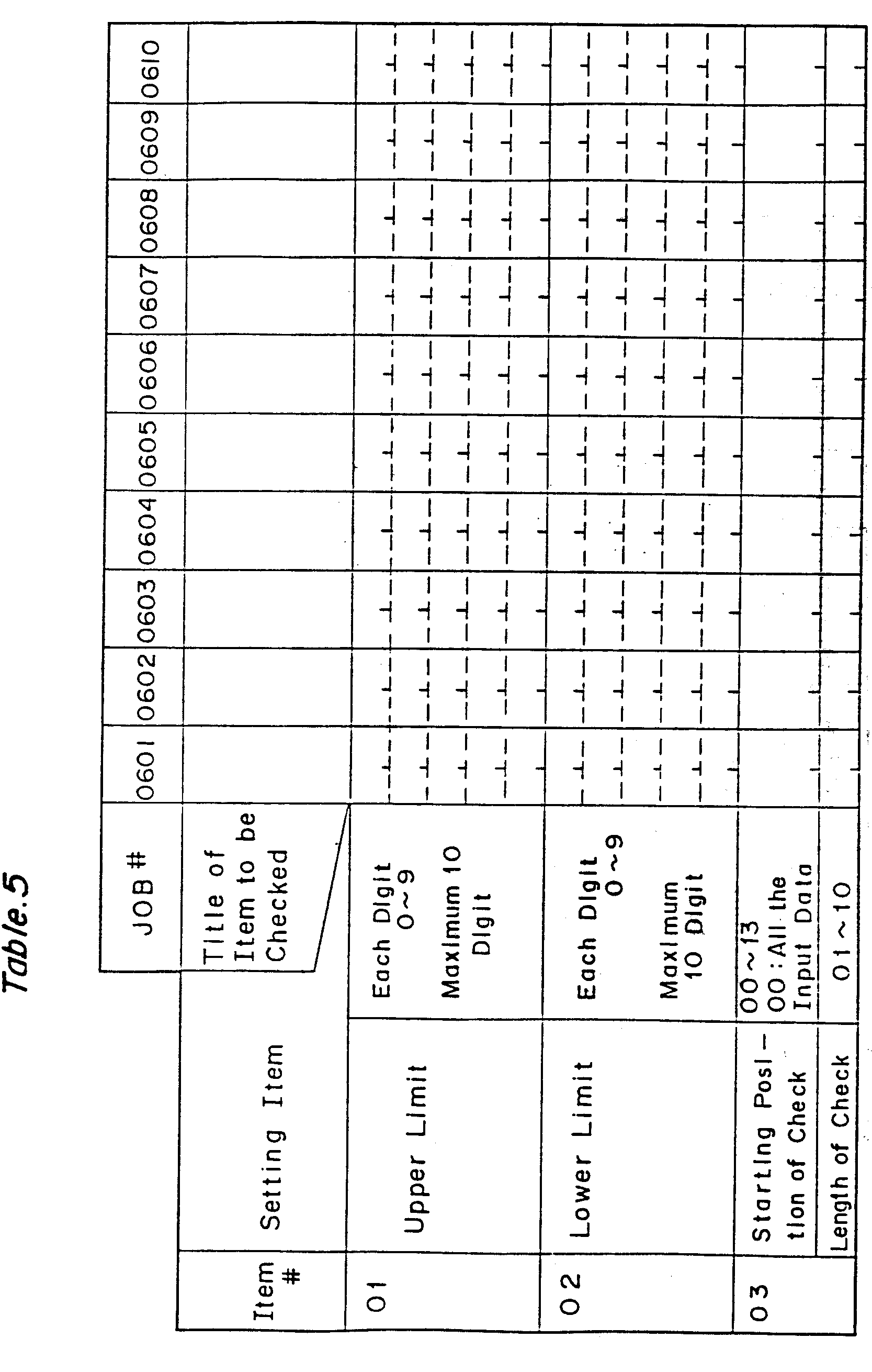


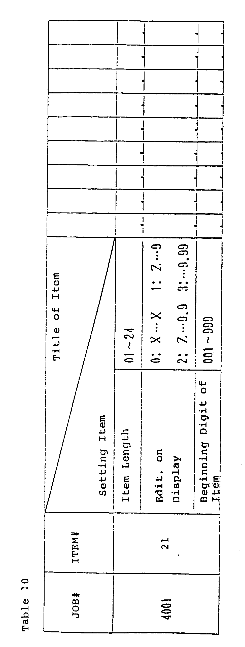


wherein
Claims (15)
characterized in that
Applications Claiming Priority (22)
| Application Number | Priority Date | Filing Date | Title |
|---|---|---|---|
| JP161948/84 | 1984-08-03 | ||
| JP161945/84 | 1984-08-03 | ||
| JP16195184A JPS6142074A (en) | 1984-08-03 | 1984-08-03 | Data input/output terminal equipment |
| JP16194884A JPS6142071A (en) | 1984-08-03 | 1984-08-03 | Data input/output terminal equipment |
| JP161952/84 | 1984-08-03 | ||
| JP16194684A JPS6142069A (en) | 1984-08-03 | 1984-08-03 | Data input/output terminal equipment |
| JP16195084A JPS6142073A (en) | 1984-08-03 | 1984-08-03 | Data input/output terminal equipment |
| JP16194984A JPS6142072A (en) | 1984-08-03 | 1984-08-03 | Data input/output terminal equipment |
| JP161946/84 | 1984-08-03 | ||
| JP161944/84 | 1984-08-03 | ||
| JP16194784A JPS6142070A (en) | 1984-08-03 | 1984-08-03 | Data input/output terminal equipment |
| JP161947/84 | 1984-08-03 | ||
| JP16194384A JPS6142067A (en) | 1984-08-03 | 1984-08-03 | Data input/output terminal equipment |
| JP16194484A JPS6142068A (en) | 1984-08-03 | 1984-08-03 | Data input/output terminal equipment |
| JP16195284A JPS6142075A (en) | 1984-08-03 | 1984-08-03 | Data input/output terminal equipment |
| JP16194284A JPS6142066A (en) | 1984-08-03 | 1984-08-03 | Data input/output terminal equipment |
| JP16194584A JPS6142037A (en) | 1984-08-03 | 1984-08-03 | Check digit checking system of data input/output use terminal equipment |
| JP161949/84 | 1984-08-03 | ||
| JP161950/84 | 1984-08-03 | ||
| JP161943/84 | 1984-08-03 | ||
| JP161942/84 | 1984-08-03 | ||
| JP161951/84 | 1984-08-03 |
Publications (3)
| Publication Number | Publication Date |
|---|---|
| EP0181438A2 EP0181438A2 (en) | 1986-05-21 |
| EP0181438A3 EP0181438A3 (en) | 1988-08-03 |
| EP0181438B1 true EP0181438B1 (en) | 1993-05-12 |
Family
ID=27582211
Family Applications (1)
| Application Number | Title | Priority Date | Filing Date |
|---|---|---|---|
| EP85109734A Expired - Lifetime EP0181438B1 (en) | 1984-08-03 | 1985-08-02 | Host-programmable input/output terminal |
Country Status (3)
| Country | Link |
|---|---|
| US (1) | US4851994A (en) |
| EP (1) | EP0181438B1 (en) |
| DE (1) | DE3587335T2 (en) |
Cited By (3)
| Publication number | Priority date | Publication date | Assignee | Title |
|---|---|---|---|---|
| US5485370A (en) | 1988-05-05 | 1996-01-16 | Transaction Technology, Inc. | Home services delivery system with intelligent terminal emulator |
| US5572572A (en) | 1988-05-05 | 1996-11-05 | Transaction Technology, Inc. | Computer and telephone apparatus with user friendly interface and enhanced integrity features |
| US5796832A (en) | 1995-11-13 | 1998-08-18 | Transaction Technology, Inc. | Wireless transaction and information system |
Families Citing this family (28)
| Publication number | Priority date | Publication date | Assignee | Title |
|---|---|---|---|---|
| US4774664A (en) * | 1985-07-01 | 1988-09-27 | Chrysler First Information Technologies Inc. | Financial data processing system and method |
| NZ224848A (en) * | 1987-07-15 | 1995-07-26 | Computer Associates Internatio | Application software created from defined modules of code |
| US5101498A (en) * | 1987-12-31 | 1992-03-31 | Texas Instruments Incorporated | Pin selectable multi-mode processor |
| US5321840A (en) * | 1988-05-05 | 1994-06-14 | Transaction Technology, Inc. | Distributed-intelligence computer system including remotely reconfigurable, telephone-type user terminal |
| US5138701A (en) * | 1988-07-12 | 1992-08-11 | Minolta Camera Kabushiki Kaisha | Data communication control system |
| CA1341310C (en) * | 1988-07-15 | 2001-10-23 | Robert Filepp | Interactive computer network and method of operation |
| US5148516A (en) * | 1988-08-30 | 1992-09-15 | Hewlett-Packard Company | Efficient computer terminal system utilizing a single slave processor |
| JP2699449B2 (en) * | 1988-09-19 | 1998-01-19 | 株式会社日立製作所 | Automatic cash transaction apparatus and cash collection method |
| US5434999A (en) * | 1988-11-09 | 1995-07-18 | Bull Cp8 | Safeguarded remote loading of service programs by authorizing loading in protected memory zones in a terminal |
| US5274810A (en) * | 1989-01-10 | 1993-12-28 | Bull Hn Information Systems Inc. | Dynamic control of program execution order on a personal computer |
| US5870724A (en) | 1989-12-08 | 1999-02-09 | Online Resources & Communications Corporation | Targeting advertising in a home retail banking delivery service |
| US5340971A (en) * | 1990-09-17 | 1994-08-23 | Metrologic Instruments, Inc. | Automatic bar code reading system having selectable long range and short range modes of operation |
| TW198107B (en) * | 1991-02-28 | 1993-01-11 | Ibm | |
| US5276863A (en) * | 1991-06-28 | 1994-01-04 | Digital Equipment Corporation | Computer system console |
| US5528490A (en) * | 1992-04-10 | 1996-06-18 | Charles E. Hill & Associates, Inc. | Electronic catalog system and method |
| JP2939050B2 (en) * | 1992-05-26 | 1999-08-25 | シャープ株式会社 | Data communication device |
| USRE44685E1 (en) * | 1994-04-28 | 2013-12-31 | Opentv, Inc. | Apparatus for transmitting and receiving executable applications as for a multimedia system, and method and system to order an item using a distributed computing system |
| US5694546A (en) | 1994-05-31 | 1997-12-02 | Reisman; Richard R. | System for automatic unattended electronic information transport between a server and a client by a vendor provided transport software with a manifest list |
| US5679938A (en) * | 1994-12-02 | 1997-10-21 | Telecheck International, Inc. | Methods and systems for interactive check authorizations |
| US5620608A (en) * | 1995-06-07 | 1997-04-15 | Cobe Laboratories, Inc. | Information entry validation system and method for a dialysis machine |
| US6009500A (en) * | 1995-06-07 | 1999-12-28 | Compaq Computer Corporation | Replacement of erroneous firmware in a redundant non-volatile memory system |
| DE69610259T2 (en) * | 1995-06-16 | 2001-03-01 | Seiko Epson Corp | Order management system |
| US5774551A (en) * | 1995-08-07 | 1998-06-30 | Sun Microsystems, Inc. | Pluggable account management interface with unified login and logout and multiple user authentication services |
| US5727147A (en) * | 1995-12-08 | 1998-03-10 | Sun Microsystems, Inc. | System and method for resolving symbolic references to externally located program files |
| US6189030B1 (en) | 1996-02-21 | 2001-02-13 | Infoseek Corporation | Method and apparatus for redirection of server external hyper-link references |
| US5970471A (en) * | 1996-03-22 | 1999-10-19 | Charles E. Hill & Associates, Inc. | Virtual catalog and product presentation method and apparatus |
| CN1447949A (en) * | 2000-08-24 | 2003-10-08 | 佐川急便株式会社 | Card payment method for service charge concering to physical distribution or transportation |
| US8082207B2 (en) * | 2004-06-17 | 2011-12-20 | Certegy Check Services, Inc. | Scored negative file system and method |
Family Cites Families (23)
| Publication number | Priority date | Publication date | Assignee | Title |
|---|---|---|---|---|
| US30785A (en) * | 1860-11-27 | William s | ||
| GB1504112A (en) * | 1976-03-17 | 1978-03-15 | Ibm | Interactive enquiry systems |
| USRE30785E (en) | 1975-02-27 | 1981-10-27 | Zentec Corporation | Microcomputer terminal system |
| US4107784A (en) * | 1975-12-22 | 1978-08-15 | Bemmelen Henri M Van | Management control terminal method and apparatus |
| US4138718A (en) * | 1977-11-14 | 1979-02-06 | Allen-Bradley Company | Numerical control system with downloading capability |
| US4231105A (en) * | 1978-07-05 | 1980-10-28 | Umc Industries, Inc. | Vendor control circuit |
| US4253157A (en) * | 1978-09-29 | 1981-02-24 | Alpex Computer Corp. | Data access system wherein subscriber terminals gain access to a data bank by telephone lines |
| US4266271A (en) * | 1978-10-10 | 1981-05-05 | Chamoff Martin E | Reconfigurable cluster of data-entry terminals |
| US4296476A (en) * | 1979-01-08 | 1981-10-20 | Atari, Inc. | Data processing system with programmable graphics generator |
| US4345315A (en) * | 1979-01-19 | 1982-08-17 | Msi Data Corporation | Customer satisfaction terminal |
| US4398250A (en) * | 1979-10-31 | 1983-08-09 | Casio Computer Co., Ltd. | Electronic cash register mutual transmission system for plurality of cash registers |
| JPS6037938B2 (en) * | 1980-12-29 | 1985-08-29 | 富士通株式会社 | information processing equipment |
| JPS57150019A (en) * | 1981-03-13 | 1982-09-16 | Hitachi Ltd | Control system of terminal device |
| JPS5854426B2 (en) * | 1981-04-08 | 1983-12-05 | 株式会社日立製作所 | portable terminal device |
| US4403303A (en) * | 1981-05-15 | 1983-09-06 | Beehive International | Terminal configuration manager |
| US4516200A (en) * | 1981-05-18 | 1985-05-07 | Texas Instruments Incorporated | Data communications system with host character terminal mode |
| EP0082225B1 (en) * | 1981-12-23 | 1987-05-06 | International Business Machines Corporation | Business system |
| US4688173A (en) * | 1982-04-26 | 1987-08-18 | Sharp Kabushiki Kaisha | Program modification system in an electronic cash register |
| US4553202A (en) * | 1982-05-06 | 1985-11-12 | International Business Machines Corporation | User controlled dialog resource switching in a multi-tasking word processor |
| US4553222A (en) * | 1983-03-14 | 1985-11-12 | Kurland Lawrence G | Integrated interactive restaurant communication system for food and entertainment processing |
| US4665501A (en) * | 1983-09-30 | 1987-05-12 | Esprit Systems, Inc. | Workstation for local and remote data processing |
| US4636947A (en) * | 1984-03-14 | 1987-01-13 | Docutel/Olivetti Corporation | ATM task scheduling system for simultaneous peripheral device transactions processing |
| US4648037A (en) * | 1984-03-15 | 1987-03-03 | Metropolitan Life Insurance Company | Method and apparatus for benefit and financial communication |
-
1985
- 1985-08-01 US US06/761,425 patent/US4851994A/en not_active Expired - Lifetime
- 1985-08-02 EP EP85109734A patent/EP0181438B1/en not_active Expired - Lifetime
- 1985-08-02 DE DE85109734T patent/DE3587335T2/en not_active Expired - Lifetime
Cited By (4)
| Publication number | Priority date | Publication date | Assignee | Title |
|---|---|---|---|---|
| US5485370A (en) | 1988-05-05 | 1996-01-16 | Transaction Technology, Inc. | Home services delivery system with intelligent terminal emulator |
| US5572572A (en) | 1988-05-05 | 1996-11-05 | Transaction Technology, Inc. | Computer and telephone apparatus with user friendly interface and enhanced integrity features |
| US5796832A (en) | 1995-11-13 | 1998-08-18 | Transaction Technology, Inc. | Wireless transaction and information system |
| US6442532B1 (en) | 1995-11-13 | 2002-08-27 | Transaction Technology Inc. | Wireless transaction and information system |
Also Published As
| Publication number | Publication date |
|---|---|
| EP0181438A2 (en) | 1986-05-21 |
| EP0181438A3 (en) | 1988-08-03 |
| DE3587335D1 (en) | 1993-06-17 |
| DE3587335T2 (en) | 1993-10-07 |
| US4851994A (en) | 1989-07-25 |
Similar Documents
| Publication | Publication Date | Title |
|---|---|---|
| EP0181438B1 (en) | Host-programmable input/output terminal | |
| US4733354A (en) | Method and apparatus for automated medical diagnosis using decision tree analysis | |
| US5283865A (en) | Computer-assisted parts sales system | |
| US3872448A (en) | Hospital data processing system | |
| US5319543A (en) | Workflow server for medical records imaging and tracking system | |
| US4855908A (en) | POS system | |
| US5774887A (en) | Customer service electronic form generating system | |
| EP0430540B1 (en) | Computerized inventory monitoring and verification system and method | |
| EP0207468B1 (en) | Method and user terminal for videotex | |
| US6233583B1 (en) | Report generator for use within a lotus notes database system | |
| US6496838B1 (en) | Database reconciliation method and system | |
| US20060265248A1 (en) | Device for automating billing reimbursement | |
| WO1990003008A1 (en) | Method and apparatus for accessing and manipulating time series | |
| US5727162A (en) | Touch screen cash register that displays merchandise keys based on sales information | |
| AU682868B2 (en) | Data retrieval system | |
| CN1348145A (en) | System and method for introducing medical installation | |
| US4085446A (en) | Data storage and retrieval system | |
| CA2085681C (en) | Indexing/compression scheme for supporting graphics and data selection | |
| JPS6115246A (en) | Compression of data for memory | |
| US4688174A (en) | Electronic cash register | |
| EP1282869A1 (en) | A data storing method and data storing structure | |
| JPH0218749B2 (en) | ||
| Pankhurst | An interactive program for the construction of identification keys | |
| Data | a. Introduction | |
| JPS6142072A (en) | Data input/output terminal equipment |
Legal Events
| Date | Code | Title | Description |
|---|---|---|---|
| PUAI | Public reference made under article 153(3) epc to a published international application that has entered the european phase |
Free format text: ORIGINAL CODE: 0009012 |
|
| AK | Designated contracting states |
Kind code of ref document: A2 Designated state(s): DE GB |
|
| 17P | Request for examination filed |
Effective date: 19861224 |
|
| PUAL | Search report despatched |
Free format text: ORIGINAL CODE: 0009013 |
|
| AK | Designated contracting states |
Kind code of ref document: A3 Designated state(s): DE GB |
|
| 17Q | First examination report despatched |
Effective date: 19900517 |
|
| GRAA | (expected) grant |
Free format text: ORIGINAL CODE: 0009210 |
|
| AK | Designated contracting states |
Kind code of ref document: B1 Designated state(s): DE GB |
|
| REF | Corresponds to: |
Ref document number: 3587335 Country of ref document: DE Date of ref document: 19930617 |
|
| REG | Reference to a national code |
Ref country code: GB Ref legal event code: IF02 |
|
| PGFP | Annual fee paid to national office [announced via postgrant information from national office to epo] |
Ref country code: GB Payment date: 20040728 Year of fee payment: 20 |
|
| PGFP | Annual fee paid to national office [announced via postgrant information from national office to epo] |
Ref country code: DE Payment date: 20040812 Year of fee payment: 20 |
|
| PG25 | Lapsed in a contracting state [announced via postgrant information from national office to epo] |
Ref country code: GB Free format text: LAPSE BECAUSE OF EXPIRATION OF PROTECTION Effective date: 20050801 |
|
| REG | Reference to a national code |
Ref country code: GB Ref legal event code: PE20 |
|
| PLBE | No opposition filed within time limit |
Free format text: ORIGINAL CODE: 0009261 |
|
| STAA | Information on the status of an ep patent application or granted ep patent |
Free format text: STATUS: NO OPPOSITION FILED WITHIN TIME LIMIT |