EP0132782A2 - System for printing encrypted messages with bar-code representation - Google Patents
System for printing encrypted messages with bar-code representation Download PDFInfo
- Publication number
- EP0132782A2 EP0132782A2 EP84108486A EP84108486A EP0132782A2 EP 0132782 A2 EP0132782 A2 EP 0132782A2 EP 84108486 A EP84108486 A EP 84108486A EP 84108486 A EP84108486 A EP 84108486A EP 0132782 A2 EP0132782 A2 EP 0132782A2
- Authority
- EP
- European Patent Office
- Prior art keywords
- code
- data
- reading
- bar
- indicia
- Prior art date
- Legal status (The legal status is an assumption and is not a legal conclusion. Google has not performed a legal analysis and makes no representation as to the accuracy of the status listed.)
- Granted
Links
Images


Classifications
-
- G—PHYSICS
- G06—COMPUTING; CALCULATING OR COUNTING
- G06K—GRAPHICAL DATA READING; PRESENTATION OF DATA; RECORD CARRIERS; HANDLING RECORD CARRIERS
- G06K1/00—Methods or arrangements for marking the record carrier in digital fashion
- G06K1/12—Methods or arrangements for marking the record carrier in digital fashion otherwise than by punching
- G06K1/121—Methods or arrangements for marking the record carrier in digital fashion otherwise than by punching by printing code marks
-
- G—PHYSICS
- G06—COMPUTING; CALCULATING OR COUNTING
- G06K—GRAPHICAL DATA READING; PRESENTATION OF DATA; RECORD CARRIERS; HANDLING RECORD CARRIERS
- G06K17/00—Methods or arrangements for effecting co-operative working between equipments covered by two or more of main groups G06K1/00 - G06K15/00, e.g. automatic card files incorporating conveying and reading operations
-
- G—PHYSICS
- G07—CHECKING-DEVICES
- G07B—TICKET-ISSUING APPARATUS; FARE-REGISTERING APPARATUS; FRANKING APPARATUS
- G07B17/00—Franking apparatus
- G07B17/00459—Details relating to mailpieces in a franking system
- G07B17/00508—Printing or attaching on mailpieces
-
- G—PHYSICS
- G07—CHECKING-DEVICES
- G07B—TICKET-ISSUING APPARATUS; FARE-REGISTERING APPARATUS; FRANKING APPARATUS
- G07B17/00—Franking apparatus
- G07B17/00185—Details internally of apparatus in a franking system, e.g. franking machine at customer or apparatus at post office
- G07B17/00435—Details specific to central, non-customer apparatus, e.g. servers at post office or vendor
- G07B2017/00443—Verification of mailpieces, e.g. by checking databases
-
- G—PHYSICS
- G07—CHECKING-DEVICES
- G07B—TICKET-ISSUING APPARATUS; FARE-REGISTERING APPARATUS; FRANKING APPARATUS
- G07B17/00—Franking apparatus
- G07B17/00459—Details relating to mailpieces in a franking system
- G07B17/00508—Printing or attaching on mailpieces
- G07B2017/00516—Details of printing apparatus
- G07B2017/00524—Printheads
- G07B2017/00548—Mechanical printhead
-
- G—PHYSICS
- G07—CHECKING-DEVICES
- G07B—TICKET-ISSUING APPARATUS; FARE-REGISTERING APPARATUS; FRANKING APPARATUS
- G07B17/00—Franking apparatus
- G07B17/00459—Details relating to mailpieces in a franking system
- G07B17/00508—Printing or attaching on mailpieces
- G07B2017/00572—Details of printed item
- G07B2017/0058—Printing of code
- G07B2017/00588—Barcode
-
- G—PHYSICS
- G07—CHECKING-DEVICES
- G07B—TICKET-ISSUING APPARATUS; FARE-REGISTERING APPARATUS; FRANKING APPARATUS
- G07B17/00—Franking apparatus
- G07B17/00459—Details relating to mailpieces in a franking system
- G07B17/00661—Sensing or measuring mailpieces
- G07B2017/00709—Scanning mailpieces
- G07B2017/00717—Reading barcodes
-
- G—PHYSICS
- G07—CHECKING-DEVICES
- G07B—TICKET-ISSUING APPARATUS; FARE-REGISTERING APPARATUS; FRANKING APPARATUS
- G07B17/00—Franking apparatus
- G07B17/00459—Details relating to mailpieces in a franking system
- G07B17/00661—Sensing or measuring mailpieces
- G07B2017/00709—Scanning mailpieces
- G07B2017/00725—Reading symbols, e.g. OCR
Abstract
Description
- This invention relates to devices for the metering of postage and similar indicia and, more particularly, to a metering device including electronic circuitry for the encryption of the indicia to be printed. ,
- Reference is hereby made to copending related patent applications assigned to the same assignee as this application; application of John Clark entitled "System Having A Character Generator For Printing Encrypted Messages", serial No. 515 073, filed on July 19, 1983, application of John Clark and Daniel Dlugos entitled "System For Printing Encrypted Messages With A Character Generator And Bar-Code Representation", serial No. 515 072, filed on July 19, 1983; and application of John Clark, Alton Eckert and David Warren entitled "System For Printing And Reading Of Encrypted Messages", serial No. 515 760, filed on July 21, 1983.
- Postage meters find extensive use, both in the United States and abroad, for imprinting postage on objects to be mailed. The postage may be applied by a self-sticking label which is imprinted by a print head enclosed within the meter, the label then being placed in adhering contact on the letter, parcel or other object to be mailed. Alternatively, the postage may be printed directly on the outer wrapping of the object being mailed. The printing apparatus is also capable of printing a short message in addition to the amounts of the postage so that, if desired, the meter can be used for the imprinting of suitable indicia designating instructions and/or routing for transport by private carrier as well as by the mail. Furthermore, if desired, the meter may be utilized for the imprinting of yet other forms of labels, such as tax stamps, assuming that governmental approval for such tax stamps is obtained.
- A serious problem which has been encountered in the use of imprinted postage is the fraudulent adulteration of such postage labels whereby, in effect, the person adulterating the postage is stealing postage. A fraudulent label may enable someone to obtain postage, or in the case of a tax stamp, to avoid paying the tax.
- It is an object of the invention to overcome the foregoing problem by providing a device or a system for metering of messages such as postage and similar indicia provided by imprinting and/or for print- ing and/or for reading of said messages and/or for veri- fying the presence of encrypted material.
- Said object is solved by the features as contained in the claims.
- The device includes electronic circuitry for the development of encryption symbology, and a print head which is driven by the electronic circuitry to imprint both the postage, or other indicia, in combination with the encryption markings. The indicia are printed in the form of a bar code wherein a set of bars is used to communicate data while a further set of bars is used to communicate encrypted material for a code word. The two sets of bars are encrypted serially so that they can be readily identified by a single bar-code reader for extraction of the characters which communicate the message and for the characters which communicate the code. An important feature of the electronic circuitry for performing the encryption process is the incorporation into the circuitry of a means for altering the encryption process in accordance with the amount of postage, the date, and, if desired, the sender and other data. Thereby, the message imprinted on the label is related to the encryption markings. In the event that the message is altered, either the encryption markings cannot be decoded or, if decoded, the resulting legend does not agree with the legend imprinted on the label.
- Further advantageous features of the invention are subject of the claims.
- The foregoing aspects and other features of the invention are explained in the following description, taken in connection with the accompanying drawings wherein:
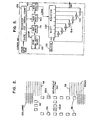
- Figure 1 shows a system incorporating the invention by imprinting delivery data, such as postage, on a package by a dot matrix printer wherein the positions of the dots have been offset to create voids as a security code;
- Figure 2 shows the arrangement of dots in a 7 x 5 matrix superposed upon a grid for identifying voids produced by displacement of the dots;
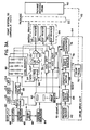
- Figure 3A is a block diagram of a first embodiment of a print system of Figure 1 utilizing a variable void coding;
- Figure 3B is a block diagram of a second embodiment of the print system of Figure 1 utilizing additional alphanumeric characters for the coding;
- Figure 3C is a block of a third embodiment of the print system of Figure 1 utilizing a bar-code form of indicia;
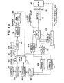
- Figure 3D is a block diagram of a fourth embodiment of the print system of Figure 1 combining features of Figures 3B and 3C;
- Figure 3E shows a modification of the system of Figure 3A for the interleaving of code and indicia by speckling;
- Figure 4A is a block diagram of a first embodiment of a read system of Figure 1 utilizing the variable void coding;
- Figure 4B is a block diagram of a second embodiment of the read system of Figure 1 for coding implemented by additional alphanumeric characters;
- Figure 4C is a block diagram of a third embodiment of the read system of Figure 1 for use with bar-code indicia;
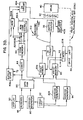
- Figure 4D is a block diagram of a fourth embodiment of the read system of Figure 1 combining features of Figures 4B and 4C; and
- Figure 4E shows a modification of the system of Figure 4A for the interleaving of code and indicia by speckling; and
- Figure 5 is a block diagram of a coder utilized in the systems of Figures 3A-D and 4A-D.
- Figure 6 shows a field of logic l's and 0's for the embodiment of Figures 3E and 4E.
- In Figure 1, a
system 20 incorporates the invention for the transmission of a mailpiece orpackage 22 from asending station 24 via adelivery system 26 to areceiving station 28. The term "package" is used only by way of example to illustrate the variety of objects which are sent from one location to another, both by use of the mail and by private carrier. Thus, the term "package" includes mailpieces such as letters, flats, envelopes, parcels and other objects which are sent via the mail, and have a surface for receipt of imprintings of postage and/or other indicia including messages. The term "package" also includes labels in those situations wherein the indicia or message is imprinted on a label which is then affixed to a mailpiece, in the case of postage, or to some other object such as bottle wherein the label is a tax stamp. Thedelivery system 26 may be any one of a number of systems such as, for example, a parcel delivery service or the postal service. The portrayal of thesystem 20 in Figure 1 is stylized to facilitate explanation of the invention, with portions of thestations mailpiece 22. - In accordance with the invention, the data is encrypted to ensure the validity of the data. The data includes, typically, the fee or postage, the date, a serial number of the
sending station 24, and, if desired, a zip code or other form of routing code for automated sorting of themailpieces 22. The encryption is accomplished by coding circuitry, to be described hereinafter, which utilizes a seed word in developing the code. The seed word is obtained from abase seed word 30 placed in both thesending station 24 and thereceiving station 28, thebase seed word 30 being altered in a manner to be described, in accordance with the date, the fee, and the serial number of thesending station 24 to provide the seed word utilized by the' coding circuitry. Thesending station 24 includes aprint system 32 for imprinting the data on themailpiece 22, while thereceiving station 28 incorporates acorresponding read system 34 for reading the data imprinting on themailpiece 22. - The
print system 32 comprises amatrix printer 36 which includes a well known set of electronically actuated dot printing points in a printing head which, in accordance with electrical signals applied to respective ones of the points, imprints a row of dots which represent a portion of a letter, numeral, or other character. For example, such a printing head may incorporate ink jets or, alternatively, may employ heat or light in the case wherein heat-sensitive labels or light-sensitive labels are utilized. Themailpiece 22 is moved along aplatform 38 of thesending station 24 by aroller 40, theroller 40 advancing themailpiece 22 beneath thematrix printer 36 as theprinter 36 imprints a succession of dots on the cover of themailpiece 22. Asensor 42 detects the presence of thepackage 22 for activating theroller 40. Thesensor 42 may have the form of any of a number of well known package sensors, to incorporate, for example, an electric eye or a roller which makes electrical contact with theroller 40. Thereby, a breaking of the light beam, or a breaking of the electric current signals the presence of thepackage 22 for activation of theroller 40 to advance thepackage 22. Theroller 40 and thematrix printer 36 are positioned by means of aframe 44 within thesending station 24. - The
receiving station 28 also incorporates aroller 40 and asensor 42 for advancing a package along aplatform 38. Aconnector 43, shown in phantom inside thesending station 24, is coupled to thesensor 42 for counting output signals of thesensor 42 to provide a count of therespective packages 22 sensed by the seh-sor 42. Theread system 34 includes amatrix sensor 46, thesensor 46 comprising a set of well known photo-electric sensors which are arranged along a row and positioned by aframe 44 as described previously for thesending station 24. The positions of the photo- electric sensors of thematrix sensor 46 corresponds to the positions of the print points of thematrix printer 36 so that the presence and absence of markings of theprinter 36 can be sensed by thematrix sensor 46. - The
sending station 24 further comprises akeyboard 48 and analphanumeric display 50. The key-board 48 includes function keys which identify the nature of the data which is being entered by data entry keys of thekeyboard 48.' Thus, for example, individual ones of the function keys are employed to identify the date, the amount of the fee, and routing data. The data to be entered appears in thedisplay 50 after which it is entered into the electronic circuitry of thesending station 24 by pushing an enter key of thekeyboard 48. Thereceiving station 28 also incorporates displays, there being adata display 52 as well as averification display 54 which indicates that the message imprinted on thepackage 22 has been verified or that it has been obliterated so as to prevent verification. - With reference also to Figure 2, there is shown a mode of encripting alphanumeric characters of the message imprinted on the
mailpiece 22. This mode of encryption, which may be referred to as variable void coding is accomplished by offsetting the dots imprinted by respective printing points of theprinter 36 so as to create voids at locations which would normally, in the absence of encryption, have imprinted dot. The field of dots in Figure 2 is defined by a matrix of seven rows by five columns. Such a matrix is a standard matrix in the printing industry and, accordingly, is most readily employed in a postage meter or similar device for the imprinting of postage and transportation data on a mailpiece. While the invention is useful for fields of both larger and smaller arrays of dots than that disclosed in Figure 2, in order to facilitate explanation of the invention, it is to be assumed in the ensuing description that the 7 x 5 matrix is to be employed. Individual ones of the dots in Figure 2 are identified by thelegends 56 while two exemplary displaceddots 56A and 56B are disclosed in phantom. The phantom view indicates the postions which adot 56 would occupy in the presence of encryption, the normal position, indicated by solid lines, being present in the absence of encryption. In particular, it is noted that the displacement associated with the encryption provides a void equal to one-half the width of thedot 56. Thus, as may be seen in the cross-bar of the letter "A" depicted in Figure 2, the offsetting of the dot 56B enlarges the space between neighboring dots, to the left of the dot 56B, while decreasing the space, be- tween neighboring dots, to the right of the dot 56B. Accordingly, the void or space between one pair of neighboring dots is increased while the void or space between another set of neighboring dots is decreased. In the encryption process, only a relatively few of the dots of an alphanumeric character are so displaced, the remaining dots maintaining their regular positions to permit identification of the character imprinted on themailpiece 22. - In accordance with a feature of the invention, a reference character without the displaced dots of the encryption process is compared to a received character having the displaced dots associated with the encryption process. The differences between the characters is thus a statement of the code.
- Figure 2 also shows a
grid 58 superposed on the character "A" to explain the operation of thematrix sensor 46. The spacing between photoelectric elements of thematrix sensor 46 corresponds to the spacing between the rows of thegrid 58, the horizontal lines being parallel to thearrow 60 which designates the direction of movement of themailpiece 22. The spacing between the rows of thegrid 58 is smaller than the spacing between centers of the elements of thematrix sensor 46 so as to permit the reading of the dots or other shaped markings of the character imprinted by theprinter 36. Similarly, the rate of reading by thematrix sensor 46 is increased to provide a spacing between columns of thegrid 58 which is smaller than the spacing between the dots of the printed character so that thematrix sensor 46 is able to respond to the variations in spacing between the dots resulting from the displacement associated with the encryption. By way of example, the spacings depicted between centers of the dots of the character in Figure 2 are four times the spacing of the cells of thegrid 58. Correspondingly, thegrid 58 provides the readsystem 34 with a resolution four times that of theprint system 32, and thereby enables theread system 34 to function even with characters that may have become partially obliterated, as well as in the situation wherein the alignment of thepackage 22 on theplatform 38 in the receivingstation 28 does not correspond precisely to the corresponding alignment in the sendingstation 24. - With reference now to Figure 3A, there is provided a more detailed description of the components of the
print system 32 of Figure 1. Thedrum 40 is mechanically coupled via aline 62 to driveunit 64 which rotates thedrum 40 for advancement of themailpiece 22. The same form ofdrive unit 64 is also provided in theread system 34 of Figure 4A, as will be described subsequently, for rotation of thedrum 40 therein. Thedrive unit 64 comprises themailpiece sensor 42, amotor drive circuit 66, a steppingmotor 68, agear train 70 mechanically coupled via a dashedline 72 to themotor 68, a shaft-angle pulser 74 also mechanically coupled via theline 72 to themotor 68, and anaddress counter 76. - In operation, the
motor 68 is energized by thedrive circuit 66 for rotation of thedrum 40 via thegear train 70. Thedrive circuit 66 is triggered into operation by thesensor 42, and continues to operate themotor 68 until thesensor 42 ceases to sense the presence of themailpiece 22. Thereby, thedrum 40 is made to rotate a sufficient amount to move themailpiece 22 past thedrum 40. The momentum of themailpiece 22 then carries it through the sendingstation 24, as well as through the receivingstation 28 as will be described substantively with respect to Figure 4A. Thegear train 70 reduces the rate of rotation of thedrum 40 to a much slower value than the rate of rotation of the output shaft of themotor 68 online 72. The shaft-angle pulser 74 comprises well known circuitry such as that of a tachometer or encoder for providing an output electrical pulse to thecounter 76 for each increment in rotation of the output shaft of themotor 68. Since thepulser 74 is mechanically locked to thedrum 40 by thegear train 70, a counting by theaddress counter 76 provides a count which corresponds precisely to the position of themailpiece 22 on theplatform 38 of the sending station'24. The leading edge of the electric output signals of thesensor 42 online 78 resets thecounter 76 back to zero upon the arrival of thenext mailpiece 22 at thesensor 42. The output count of thecounter 76 will be utilized, as described hereinafter, for addressing components of theprint system 32 for operation of thematrix printer 36. - The
print system 32 further comprises anaddress generator 80, atiming unit 82 anaddress generator 84, a RAM 86 (random access memory) for the storage of data entered from other components including thekeyboard 48 and thecounter 43, acoder 88 for providing the encripting code as will be more fully described in Figure 5, amemory 90, amemory 92, and a set ofvoid units 94 for driving respective ones of a set of print points 96 of thematrix printer 36. Eachvoid unit 94 is utilized for incorporating digits of the encryption code which are stored in thememory 92 into the printing process for displacing dots of the character matrix in accordance with the variable-void feature of the invention. Eachvoid unit 94 comprises ashift register 98, two AND gates 101-102, and anOR gate 103. In the ANDgate 102, of the input terminals thereof is complimented, this terminal being coupled along with a corresponding terminal (not complimented) of thegate 101 to thecode memory 92. - In operation, a person utilizing the sending
station 24 enters data into theRAM 86 by use of the keys of thekeyboard 48. As has been noted hereinabove, thekeyboard 48 is also coupled to thedisplay 50 for displaying the data which is to be entered into theRAM 86. During entry of the data, the signals of the keys of thekeyboard 48 are also applied to theaddress generator 80 to activate thegenerator 80 to address theRAM 86 to designate the locations wherein the data of thekeyboard 48 is to be stored within theRAM 86. Thegenerator 80 is also utilized for addressing theRAM 86 during the outputting of data from theRAM 86 to thecoder 88 and to thememory 90, the action of thegenerator 80 initiated by signals of thetiming unit 82 during the outputting of the storage data. Thetiming unit 82 also initiates activity of theaddress generator 84 to designate locations within thememory 90 for receiving data from theRAM 86. Thecoder 88 utilizes the data of theram 86 in providing the digits which are stored in thecode memory 92, and thememory 90 is utilized for applying the data of theRAM 86 via thevoid units 94 to the print points 96 of thematrix printer 36. - During the first stage of the operation of the sending
station 24, the data such as the amount of postage, the routing as via zip code, the date and the package count of thecounter 43 are entered into theRAM 86 for the subsequent imprinting of a message on thepackage 22. The message includes the date, the package count, the serial number of the sendingstation 24, the delivery fee or postage, and optionally zip code and/or city, state of the origination. In accordance with the invention, the message also includes, in encrypted form, a verification of the message showing that the message was indeed printed by the sendingstation 24, and not by an impostor. - Accordingly, the second stage in the operation is the transfer of data from the
RAM 86 to thecoder 88 for the generation of the encrypted verification, and to thememory 90 for operation of thematrix printer 36. The first two stages are initiated sequentially in response to the aforementioned signals of thetiming unit 82 to thegenerators coder 88 generates the requisite code and applies the digits for control of the encryption process to thecode memory 92 in a manner to be described subsequently with reference to Figure 5. - The third stage of the operation begins when the
package sensor 42 has detected the presence of amailpiece 22 or other object such as a letter which is to be mailed. As has been noted above, thesensor 42 resets thecounter 76 and initiates operation of themotor drive circuit 66 with the resultant counting of thecounter 76. The counter 76 counts out successive addresses of both theprint memory 90 and thecode memory 92 for transferring the data contained therein to thematrix printer 36. During the transfer of data from theRAM 86 to thememory 90, the data is arranged in accordance with the rows of dots of the matrix of each character which is to be imprinted on themailpiece 22. Thus, in response to each designation of character by thekeyboard 48, theRAM 86 makes available to thememory 90 the succession of dots for each row of the characters matrix as has been explained with reference to Figure 2. Accordingly, upon transfer of the data from theRAM 86 to individual sections of theprint memory 90, respective sections of thememory 90 store the requisite sequence of dots which are to be applied by the corresponding print points 96 to themailpiece 22 during the printing operation. - In response to the addressing by the
counter 76, the data is read out of the respective section of thememory 90 and of the respective sections of thememory 92 into the correspondingvoid units 94 for application to the correspondingprintheads 96. With respect to the operation of thevoid units 94, eachvoid unit 94 operates in the same manner. In eachvoid unit 94, data from thememory 90 is applied to an input terminal of theshift register 98 through which it is clocked at a higher rate than the entry of data from thememory 90 into theregister 98. For example, the rate of clocking in theregister 98 may be at a rate four times greater than the rate of entry of the data from thememory 90 into theregister 98. The clocking is accomplished in response to clock pulses applied at terminal C from a clock (not shown) within thetiming unit 82. - The foregoing factor of four in the clock rate corresponds to the factor of four (described in Figure 2) between a dot of the printed character and a cell of the
grid 58. Thus, as a digital signal enters theshift register 98 from thememory 90, the digital signal then propagates rapidly through theshift register 98 through successive cells thereof. As these digital signals propagate through theshift register 98, themailpiece 22 is advanced by rotation of the drum 40. Each increment in time associated with the propagation from cell to cell of theshift register 98 corresponds to an increment in postion of'the packag 22 Each cell of theregister 98 is provided with an output tap or terminal whereby a signal can be extracted after a predetermined amount of delay from the time of transfer of the signal from thememory 90 to theshift register 98. - Each row of the
code memory 92 is coupled to a corresponding one of thevoid units 94. More specifically, as has been described above, in eachvoid unit 94, an output line of thecode memory 92 is applied to an input terminal of each of the gates 101-102. In response to the outputting of alogic 0 signal from thecode memory 92, the ANDgate 102 is activated due to the complementing of its input terminal coupled to thememory 92. With the activating of the ANDgate 102, the digital signals of theshift register 98 are cou- pled via the ANDgate 102 and theOR gate 103 to theprint point 96. In response to the outputting of alogic 1 signal from thecode memory 92, the ANDgate 102 is deactivated and the ANDgate 101 is activated to pass a digital signal from theshift register 98 via theOR gate 103 to theprinthead 96. Since the ANDgate 101 is coupled to a cell of theregister 98 downstream from the connection of the ANDgate 102 to a cell of theregister 98, the activation of thegate 101 results in a delay of the operation of' theprint point 96. In view of the continuous motion of thepackage 92 by the rotation of thedrum 40, the delay introduced by thegate 101 results in a displacement of the position of the dots, such as the previously described displacement of thedots 56A-B of Figure 2. In view of the ratio of four cells of thegrid 58 corresponding to the spacing between centers of thedots 56 of Figure 2, the delay of one of the registers 98 (as depicted by the connections of thegates dot 56 as depicted in Figure 2. Accordingly, for each occurrence of alogic 1 from thecode memory 92, there is presented a corresponding displacement in the position of a dot of the character in Figure 2. For ease of portraying such displacements, only two such displacements are shown in the Figure, this being the displacement of thedots 56A-B. With the displacement, there is created a void at the site where thedot 56 would have been located in the absence of the encripting command from the signals of thecode memory 92. Thus, avoid unit 94 has introduced a void into the printed character so as to encrypt the character with a code that is to be utilized for verifying the printed message. - With reference to Figure 4A, the
read system 34 operates in a manner complementary to that of theprint system 32 of Figure 3A. As has been noted hereinabove, the receivingstation 28 includes adrum drive unit 64 for rotating adrum 40 to advance thepackage 22 beneath thematrix sensor 46. Thereset line 78 of thedrive unit 64 is also utilized to reset atiming unit 106 which provides timing signals at terminals Tl and T2 for operating components of thesystem 34 as will now be described. - The
read system 34 comprises a RAM 108, acorrelator 110, anaddress generator 112, amemory 114,buffer storage unit 117-118, aRAM 120, anaddress generator 122, asubtractor 124, amemory 126 and acorrelator 128. Also included in thesystem 34 are thedata display 52 and theverification display 54, previously described with reference to Figure 1, as well as an optional display 52A. In addition, thesystem 34 includes acoder 88 and acode memory 92 which have been described with reference to Figure 3A. - In operation, upon the sensing of a
mailpiece 22 at the receiving station 28 (Figure 1), theaddress counter 76 of thedrive unit 64 addresses theRAM 108 to enter data from thematrix sensor 46 as themailpiece 22 moves along theplatform 38. The counting of thecounter 76 is synchronized with the movement of thepackage 22 by the shaft-angle pulser 74. Thecounter 76 includes an additional terminal designated as terminal A in Figures 3 and 4, for providing a high speed counting at a rate four times that of the addressing rate utilized in theprint system 32 of Figure 3A. This is readily accomplished by deleting the least-significant bits from the lower rate counting output terminal of thecounter 76. The counting rate at the terminal A of thecounter 76 is utilized in Figure 4A to address theRA M 108 at the rate corresponding to the density of the cells of thegrid 58 in Figure 2. Thus, as thepackage 22 advances past thematrix sensor 46, the signals of the photo-electric elements of thematrix sensor 46 are sampled and are entered into theRAM 108 at the rate four columns of thegrid 58 for each column ofdots 56 of the character in Figure 2. In addition, the close spacing of the photo-electric elements of thematrix sensor 46 provide for four rows of samples, in thegrid 58 for each row ofdots 56 of the character in Figure 2. Thematrix sensor 46 extends well beyond the top and bottom of the text printed on the bottom of themailpiece 22 to be able to receive the printed message even if the imprint on themailpiece 22 is slightly offset from the position of thematrix sensor 46. - The operation continues with the
correlator 110, theaddress generator 112, thememory 114 and thebuffer storage units correlator 110 is initiated by a signal of thetiming unit 106 subsequent to the storing of the data in theRAM 108. The timing signal is obtained with the aid of thepackage sensor 42 which changes the state of the signal online 78 from alogic 1 to alogic 0 when themailpiece 22 has completely passed by thesensor 42. Thereby, thetiming unit 106 is signalled by thesensor 42 that the reading of data by thematrix sensor 46 has been completed and that accordingly, the stored data can be outputted from theRAM 108. - The
correlator 110 and theaddress generator 112 react with theRAM 108 in a well known fashion for transferring the message from theRAM 108 to thestorage unit 117. Automated readers of printed matter are commercially available, and are equipped with circuitry for extraction of the message even if the object being read is slightly offset from the orientation of the reading head. Such an adjustment offsetting is readily accomplished by correlating received symbols with symbols stored in a reference memory, this being thememory 114. By cycling through the various storage cells of theRAM 108, thecorrelator 110 correlates the individual characters stored in theRAM 108 with the reference characters of thememory 114 so as to determine which characters, or symbols have actually been sensed by thematrix sensor 46. When a correlation is obtained between the received symbol and the reference symbol, thecorrelator 110 triggers thegenerator 112 to address a location in thestorage unit 117 for entering the received symbol. Simultaneously, with the using of thestorage unit 117, thegenerator 112 also addresses thestorage unit 118 for entering the reference symbol from thememory 114. The character, or symbol, stored in thestorage unit 117 differs from that stored in thestorage unit 118 in that the received character of thestorage unit 117 includes the variable voids of the encryption process while the characters stored in thestorage unit 118 is free of the voids of the encryption process. The succession of reference characters entered into thestorage unit 118 are also applied via thememory 114 and theaddress generator 112 to theRAM 120 so as to store the data of the complete message in theRAM 120. - The final step in the operation of the
read system 34 can now be accomplished by utilizing the data stored in the storage units 117-118 and in theRAM 120. First, it is noted that the reference symbols are provided by thememory 114 to thecorrelator 110 and to thestorage unit 118 in the form of the dot matrix presented in Figure 2 so that a comparison can be made between the dot-matrix representation of the character in thestorage unit 117. With respect to theRAM 120, thememory 114 provides only a digital word identifying each of the characters. Since thestorage unit 118 contains the complete dot-matrix representation of each symbol, the symbols are readily outputted from thestorage unit 118 directly to the data display '52. Thereby, as the characters are successively outputted from thestorage units 118 to thedisplay 52, the entire message builds up within thedisplay 52 for presentation to a person utilizing the receivingstation 28 of Figure 1. - In accordance with a feature of the invention, the verification of the received message is obtained by comparing the received characters of the
storage unit 117 with the corresponding reference characters of thestorage units 118. This is accomplished by subtracting, cell by cell in accordance with thegrid 58, the data stored in thestorage unit 118 from the data stored in thestorage unit 117. The cell- by-cell process is implemented by sequentially addressing the respective storage locations by theaddress generator 122. Theaddress generator 122 is operated in response to a timing signal from thetiming unit 106 so as to implement the foregoing addressing after thecorrelator 110 has directed the entry of the characters into the storage units 117-118. The subtraction is accomplished by thesubtracter 124, and the results of the subtraction are entered into thememory 126 in response to an addressing thereof by thegenerator 122. It is readily appreciated that, with reference to a comparison of the characters stored in the two storage units 117-118, that in the event that corresponding cells of the grid 5.8 have equal value of logic signals, thelogic 0 or alogic 1, then the output of thesubtractor 124 is zero. On the other hand, if a void is present due to the encryption process, then the logic value stored at the corresponding grid cells will differ and, accordingly, thesubtractor 124 will output alogic 1 to thememory 126. Thereby, thememory 126 stores a representation of the encryption code as received by the receivingstation 28. Assuming that there has been no obliteration of the printed message, and that the printed message is a valid message as distinguished from a message printed by an impostor, then the array of data stored in thecode memory 126 will be identical to the array of data stored in thecode memory 92 of Figure 3A. - The data stored in the
code memory 126 is to be compared with the data of thecode memory 92 to determine that a valid message has been transmitted. Accordingly, thecoder 88 of Figure 4A is activated with the received data in the RAM 12D in the same manner as was described previously for the activation of thecoder 88 with the data of theRAM 86 in Figure 3A. The coder 88 (Figure 4A) then generates the reference code for storage in thememory 92. The codes of thememories correlator 128 which signals the display -54 to indicate a verification upon the obtaining of a good correlation, or to show obliteration, in the event that an inadequate correlation is obtained. It.is to be understood that an inadequate correlation can be due to either obliteration or the act of an impostor. In either case, the user of the receivingstation 28 has been alerted to the fact that the message imprinted on themailpiece 22 cannot be verified. Both thecorrelators package 22 which will pr6vide a less than perfect correlation even with a valid message. - If desired, the display 52A may be used to present the alphanumeric indicia with the variable void coding. For this purpose, the output signals of the
storage unit 117, in addition to being coupled to thesubtractor 124, are also coupled to the display 52A. In addition, the foregoing output signals, of thesubtractor 124 are also coupled to the display 52A, these signals being synchronized with corresponding ones of thestorage unit 117 and indicating the presence of a displaced pixel. In response to the subtractor signals, the display 52A provides for a blinking or coloring of the displaced pixels so that personnel utilizing theread system 34 can readily observe the coding of the indicia. - With reference to Figure 5, there is shown a simplified representation of a
coder 88. Coding devices are readily available commercially and by way of example, a maximal-length shift-register code generator is described in Figure 5. Thecoder 88 comprises ashift register 130, which stores a seed word, and is driven by aclock 132. A set of modulo-2adders 134 sum the contents of successive ones of the cells of the shift register, with the resultant sum being inputted to the first cell of theregister 130. The contents of the right-hand cell of the shift register 130' is designated as the output terminal of thecoder 88. - In accordance with a feature of the invention, the seed word is generated by use of input data relating to one or more parameters such as the date, the fee, the serial number of the sending
station 24, and the count of mailpieces and other packages provided by thecounter 43. Accordingly, thecoder 88 further comprises aregister 136 for receipt of the input data, a ROM (read only memory) 138 and three adders 141-143. TheROM 138 stores a set of seed words which are addressed in accordance with the three least significant bits of the data, there being accordingly eight base seed words stored in theROM 138. The selected base seed word is then added modulo-2 with the fee at theadder 141 and again added modulo-2 with the serial number of the sendingstation 24 at theadder 142, and again added modulo-2 with the piece count of thecounter 43. The serial number is being permanently stored in theregister 136. The output digital word of theadder 143 is then loaded into theshift register 130 to serve as the seed word from which the code is generated by thecoder 38. - It is to be understood that the foregoing contributions to the seed word are presented by way of example. Thus, if desired, the contribution of the serial number and/or the fee may be deleted. The use of the date and the piece count in the composition of the seed word is advantageous in providing a seed word which varies from mailpiece to mailpiece and from day to day, a clear benefit for improved security. In the event that a microprocessor (not shown) be incorporated in the sending
station 24 and the receivingstation 28, other forms of codes can be generated such as those of the National Bureau of Standards based on the multiplication of pairs of large numbers. - The foregoing print system and read system has provided an effective way of introducing an encrypted code into a printed message which can readily verify the validity of the message. The use of the variable voids permits the message to be read either manually or by machine, while obtaining the encrypted identification. It is also noted that the foregoing systems also are applicable for any form of printed symbol, whether readable manually or only by machine. Thereby, if desired, the imprintings on the
mailpiece 22 can be accomplished with a set of nonsense symbols which are recognizable only by use of the stored reference symbols in the read system. Thereby, a system for assuring payment of the fee imprinted for postage, taxes and other purposes has been disclosed. - It is furthermore noted that the message need not be imprinted only on a flat type of package but that, if desired, the message may be imprinted on a label or stamp which can later be affixed by labeling equipment to a container such as a bottle. Thereby, the system of the invention can also be utilized for the affixation of tax stamps to liquor bottles as well as to other objects requiring a tax. The reading process can then be accomplished automatically, and has been described hereinabove, by use of a conveyor (not shown) to move the bottle or other objects past the matrix sensor for reading the legend imprinted on the tax stamp or other label. Thereby, fraudulent stamps or labels can be detected.
- By way of alternative embodiments, it is noted that the security can be obtained by having a set of characters which designate the date, the fee, the piece count and the serial number of sending the station, with additional characters being supplied as a code. The characters of the code are based on the values the date, the fee and the serial number as has been disclosed in the previous embodiment. The code characters may be applied after piece count, or interleaved therewith. In.either event, a predetermined timing arrangement is utilized as to determine which of the characters represent the data, and which of the characters represent the code.
- Figure 3B shows a
print system 200 which is an alternative embodiment of theprint system 32 of Figure 3A. Thesystem 200 provides for the printing of data characters plus code characters, and includes many of the components of thesystem 32. Thesystem 200 comprises a ROM (read-only memory) 201, aprint memory 202, anaddress generator 204, an ORcircuit 206, and atiming unit 208 which provides for the arrangement of the characters as is portrayed in thegraph 210. Also included in thesystem 200 are components which have been previously described, namely, thedisplay 50, thekeyboard 48, theaddress generator 80, thetiming unit 82, theaddress generator 84, theRAM 86, thecoder 88, theprint memory 90, thedrive unit 64, thecode memory 92, thematrix printer 36, and thedrum 40. Since theprint system 200 provides both the data and the coding by means of alphanumerics, thematrix printer 36 may be replaced by some other form (not shown) of alphanumeric printer if desired. - The operation of the
system 200 follows that of thesystem 32. Thus, thecoder 88 provides a code word based on the date, the fee, the serial number, and the piece count which then produces the code in thememory 92. The output terminals of thememory 92 provide an address for selecting a code symbol or code character from theROM 201. Theprint memory 90, under instruction from theaddress generator 84, stores the data which is to be printed on themailpiece 22. Similarly, theprint memory 202, under instruction from theaddress generator 204 stores the code characters which are to be imprinted on themailpiece 22. The operation of thegenerators timing unit 82. The arrangement of the contents of thememory 202 follows that of thememory 90 so that the contents of thememory 202 can be applied directly to thematrix printer 36. The data of thememory 90 and the code of thememory 202 are coupled alternately via theOR circuit 206 to thematrix printer 36. Timing signals for operation of the read out of the contents of thememories timing unit 208, thetiming unit 208 being driven by an output signal of theaddress counter 76 of thedrive unit 64. Thereby, as thedrum 40 advances thepackage 22 before theprinter 36, theprinter 36 imprints the package with both the data characters and the code characters as is portrayed in thegraph 210. - One relatively simple form of code which may be imprinted on a mailpiece or other form of
package 22 consists of a four-digit number representing the piece count of thecounter 43 followed by a one digit code number. The coding operation (Figure 5) involves the modification of a base seed word by key board-entered data such as the fee and the date. Other data such as the serial number and the piece count are entered automatically into the RAM 86 for use by thecoder 88. - As an example of still further data'which may be utilized by the
coder 88, in lieu of the foregoing or in addition thereto, are the total amount of prepaid postage stored in a system ofregisters 212 and the weight of a mailpiece orpackage 22 as provided by ascale 214. Theregister system 212 and thescale 214 are connected to theRAM 86, as shown in phantom in Figure 3B, and also appear in Figure 1. With reference to Figure 5, theregister 136 of thecoder 88 would be enlarged to include the weight and total prepaid postage, and additional adders (not shown) such as theadder 141 would be employed to combine the weight and postage with the base seed word. - Figure 4B presents the companion read
system 220 for theprint system 200. Thesystem 220 is substantially less complex than the readsystem 34, the reduced complexity being obtained by a manual entry of the printed data on themailpiece 22 into thesystem 220. Upon entry of the printed data into thesystem 220, the date, the fee, the piece count and the serial number are utilized, as previously described with reference .to theread system 34, to produce the corresponding code. If the piece weight is utilized, the package is weighted and the weight is entered at the keyboard. If the prepaid postage is utilized for assumed transmission by the postal service, such value is known at the post office (herein the receiving station 28) so as to be enterable by the keyboard. In theread system 220, the regenerated reference code appears on a display for visual comparison by an operator of the system. - The
system 220 comprises thekeyboard 48, thedisplay 50, theRAM 86, thecoder 88 and thecode memory 92 which have been previously described with reference to Figures 3A and 3B. In addition, thesystem 220 includes theROM 201, previously described in Figure 3B and adisplay 222. In operation, the person using thesystem 220 reads the message printed on themailpiece 22, and enters the characters via thekeyboard 48. Thekeyboard 48 activates thedisplay 50 to show the characters entered, thus, providing the message comprising the date, the fee, piece count and the serial number of sending station. Thekeyboard 48 also activates theRAM 86 to provide the date, the fee the piece count and the serial number (and the weight and prepaid postage if this date is utilized) to thecoder 88 which utilizes this data to produce the code in thememory 92. The code words in thememory 92 then address aROM 201 to produce the code characters on thedisplay 222. In the event that the data has been improperly entered into thekeyboard 48, a bogus address may be applied by thecode memory 92 to theROM 201 in which case a fault indicator will be illuminated on thedisplay 222 to alert the operator of the system. Alternatively, if there has been a tampering with the message imprinted on the package, thedisplay 222 may show a set of code characters, however, the set shown on thedisplay 222 will differ from that actually imprinted on thepackage 22. Thereby, the operator of thesystem 220 has been alerted to a tampering of the printed message. - With respect to the
read system 220, it is noted that should it be desirable to have automatic reading instead of the manual inputting, theread system 34 of Figure 4A is readily modified to provide the function of thesystem 220 of Figure 4B. ' Such modification is attained by replacing the correlator 110 (Figure 4A) with a timing unit, corresponding to thetiming unit 208 of Figure 3B, for alternately switching the data and the code characters received from the photosensor 46 into thebuffer storage units ROM 201 would be connected betweencode memory 92 andcorrelator 128, and thebuffer storage unit 117 would be coupled directly to thecorrelator 128. Thus, thecorrelator 128 would directly correlate the set of code characters which was read from thepackage 22 with the set of code characters of the reference. Upon obtaining a proper correlation, thedisplay 54 would indicate verification of the printed message. - The message printed on the
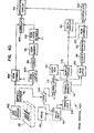
mailpiece 22 by the succession of characters, as disclosed in Figure 3B, may alternatively be printed by means of a bar code as is now disclosed in the print system 400 of Figure 3C. The print system 400 has components previously described with reference to theprint system 200 of Figure 3B, these components being thekeyboard 48, theRAM 86, thecoder 88, thecode memory 92 and theROM 201. The operation of the system 400 follows that of thesystem 200 and, accordingly, the characters commanded by thekeyboard 48 are applied by theRAM 86 to thecoder 88, and also to abuffer storage unit 402. Thecoder 88 utilizes the information of the date, the fee, and the serial number of the sending station to generate the coded words which are stored in thememory 92. If desired, the piece count may also be utilized. The output lines of thememory 92 address theROM 201 to select suitable alphanumeric characters which can be printed by a bar code printer. The system 400 further comprises an ORcircuit 404 and abar code printer 406, with theOR circuit 404 being connected to output terminals of both the ROM 201 and thestorage unit 402 for alternately coupling the output signals to theprinter 406. The alternate coupling is accomplished by timing signals provided by a timing unit such as thetiming unit 208 which was utilized in thesystem 200 of Figure 3B. Theprinter 406 is understood to include the generator and other circuitry commonly found in bar code printers for converting the character command signal to a succession of lines of the bar code (not shown). The printer '406 then imprints the bar code on themailpiece 22. The presentation of the printed message on themailpiece 22 follows that disclosed in thegraph 210 of Figure 3B. - The companion read
system 420 for the print system 400 is disclosed in Figure 4C. Thesystem 420 functions in a manner analagous to that of theread system 34 of Figure 4A, and contains some of the components of thesystem 34 as well as components of the print system 400 of Figure 3C. Thesystem 420 comprises thedrum 40, thedrive unit 64, thetiming unit 106, thecoder 88, thecode memory 92, theROM 201 and theverification display 54 previously disclosed in Figures 4A and 3C. In addition, thesystem 420 comprises abar code reader 422 of well-known configuration, aROM 424 for converting output digital signals of thereader 422 to the actual symbol represented by thereader 422, aROM 426 for converting the output digital signal of thereader 422 to the input digital format utilized by thecoder 88, and acorrelator 428. Both the bar code printer. 406 of Figure 3C and thereader 422 as well as the actual code are well known and are in common use. A portion of a bar code is portrayed, by way of example, on themailpiece 22. - In operation,, the
drum 40 advances the .mailpiece before thereader 422, enabling thereader 422 to read the code and apply the resultant characters of the reading to theROMs 424 and 426: Thedrum 40 is driven by thedrive unit 64 which, as has been disclosed previously, with respect to Figure 4A, activates thetiming unit 106 to provide timing signals synchronized to the movement of thedrum 40 and thepackage 22. The output data of theROM 426, comprising the date, the fee, and the serial number of the sending station, and/or other data is loaded into thecoder 88. Thecoder 88 utilizes the foregoing data to provide code words which are stored in thememory 92 and are applied as addresses to theROM 201 for providing alphanumeric symbols corresponding to the code words. The generation of the alphanumeric symbols by theROM 201 in Figure 4C is the same as the symbols generated by theROM 201 of the print system 400 in Figures 3C, assuming that the bar code was validly imprinted on themailpiece 22. The contents of theROM 424' and 201 may comprise the actual form of the respective symbols or, alternatively, may comprise a digital word identifying the alphanumeric symbol. In either case, the contents of theROM 424 and theROM 201 are clocked out by signals of thetiming unit 106 into thecorrelator 428. Thecorrelator 428 correlates the symbols of therespective ROMs reader 422 agree with those predicted by the operation of thecoder 88 based on the date, the fee, and the serial number of the sending station. Upon obtaining a satisfactory correlation, thecorrelator 428 activates thedisplay 54 to show verification of the printed message. - It is further noted that a mailpiece sorting system (not shown) may be coupled to the bar-
code reader 422 for use in those situations wherein a zip code or other routing code has been imprinted on the package. Upon recognition of the routing code, the sorter then dispenses various packages in a series of such packages into various bins for automatic sorting of mail and similar packages. The output signal of thecorrelator 428 may be utilized to activate the sorter so that no sorting takes place unless the message imprinted by the bar code on thepackage 22 has been declared valid. Thereby, an automatic sorting system can be used with a secure routing indicia imprinted on the packages. - The
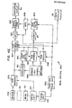
alphanumeric print system 200 of Figure 3B and the bar-code print system 400 of Figure 3C may be combined to form theprint system 600 of Figure 3D. In comparing Figures 3C and 3B with 3D, it may be seen that each of these systems employ thekeyboard 48, theRAM 86 thecoder 88, thecode memory 92 and thedrum 40. Accordingly, the combinedsystem 600 uses the foregoing components to activate both thematrix printer 36 and the bar-code printer 406. In the physical construction of thesystem 600, the twoprinters - If desired, the bar-
code printer 406 could employ the apparatus of the matrix print head of theprinter 36, in which case each bar of the code would be printed as an array of closely spaced dots. Furthermore, if the alphanumerics and the bar code are to be printed sequentially, rather than side-by-side, then a single print head could be used for both imprintings with the control circuitry being alternately switched from the alphanumerics to the bar code. This system is advantageous in that it permits the automatic sorting of mail, the automatic verification of the indicia, as well as the manual reading of the indicia so that personnel handling packages and mail can visually identify the imprinted legends if they so desire. - The companion read
system 620 is shown in Figure 4D. Thesystem 620 incorporates components of thesystem 34 of Figure 4A for reading printed alphanumeric characters and other symbols. Also included are both the bar-code reader 422 and thematrix sensor 46 for reading respectively the bar code and the alphanumeric characters. Also included are thedrum 40, thedrive unit 64 and the timingunits 106 of both Figures 4A and 4C. Interpretation of the bar code is accomplished with the aid of theROMs coder 88, thecode memory 92 and theROM 201 of Figure 4C. The character processing is implemented by use of theRAM 108, thecorrelator 110, theaddress generator 112, thesymbol memory 114, thebuffer storage 118 and theRAM 120 of Figure 4A. Also included, by way of a second channel in the signal processing of thesystem 620 are thecoder 88, thecode memory 92, thesymbol ROM 201 and thecorrelator 128. TheRAM 120, thecoder 88 and thememory 92 function as was disclosed with reference to Figure 4A. By use of theROM 201, addressed by thememory 92, the character predicted by the coding operation is attained in a manner corresponding to that disclosed in Figure 4C. The predicted character from theROM 201 and the actually received character from thebuffer storage units 118 are correlated by thecorrelator 128. The output of the correlation is applied to the verification display 54' along with the output of thecorrelator 428. Thereby, correlation and verification can be obtained from the examination of the bar code or from examination of the alphanumeric code characters. Thedisplay 54 will respond to a positive correlation from either of thecorrelators display 52 displays the characters which have been received, this includes both the data characters and the characters of the code. In thesystem 620, while the complete array of characters is displayed for an operator of the system, the correlation is accomplished automatically without aid of the operator, as distinguished from the manually-aided read-system 220 of Figure 4B. - With reference now to Figures 3E, 4E and 6, there is described an alternative form of the print and read systems utilizing an interleaving of the code with the indicia by speckling the indicia with portions of a code disposed as 1's and 0's across the field of the indicia. Such speckling is shown in Figure 6, while the
corresponding print system 800 and theread system 850 are shown, respectively, in Figures 3E and 4E, - The
print system 800 is a modification of thesystem 32 of Figure 3A and incorporates thekeyboard 48, theaddress generator 80, thepiece counter 43, thecoder 88, thedrive unit 64, and thedrum 40 shown previously in Figure 4A. Instead of the 7 by 5 matrix format previously described, a larger field is employed to more easily implement the speckling procedure. For example, a 9 by 9 or larger matrix may be employed. Accordingly, the matrix printer of Figure 3A has been replaced by a larger-format printer 36A in Figure 3E. Thesystem 800 further comprises RAM's 802 and 804, ROM's 806 and 808, and a set ofswitches 810 of which there is one switch for each row of the indicia matrix. Eachswitch 810 comprises two AND gates 811 - 812, and anOR gate 813. - The speckling procedure, as demonstrated in Figure 6, interjects light areas into the dark coloration of the indicia, such as the
exemplary numerals 2 and 3 of Figure 6, and interjects dark areas into the relatively light coloration of the background. Thelogic 1's represent points of impact of the print head while thelogic 0's represent areas where no markings have been applied by the print head. In each symbol field, regions have been set aside for the speckling, the speckling in each of the regions being done on a random or pseudorandom basis. - In operation, the
keyboard 48 and thecounter 43 input data into thememory 802 in accordance with addresses provided by thegenerator 80. As has been described previously, thecounter 43 counts mail pieces, packages, and other forms of parcels and labels which pass by thematrix printer 36A for the imprinting of postage or other message. Amailpiece 22 is shown in phantom as it is moved past the head of thematrix printer 36A by thedrum 40. The data stored in thememory 802 forms the message which is to be imprinted on themailpiece 22. Other sources of data such as the weight and serial number, described hereinabove, have been deleted in Figure 3E to facilitate the description. The data stored in thememory 802 is applied to thecoder 88 for the formation of the field of 1's and 0's, which field is. stored -in thememory 804. The arrangement of the stored field is similar to that shown in thememory 92 of. Figure 3A, the stored field being larger in thememory 804 to accommodate the larger array of the indicia of Figure 6. - The
matrix printer 36A comprises a set of print points 96, as does theprinter 36 of Figure 3A, for printing a set of dots to form each symbol of the indicia. The rows and columns of the dots for each symbol are stored in the read-only memory 806, the dots of the respective rows being applied via corresponding ones of theswitches 810 to. the respective print points 96 of theprinter 36A. The stored data in theRAM 802 is applied to theROM 806 as an address to select the sequence of symbols for which theROM 806 is to supply the dots to theprinter 36A. Each of theswitches 810, in addition to receiving the dots for a specific row of a symbol, also receives the dots from theRAM 804 for a specific row of the code. The speckling is accomplished by momentarily operating individual ones of theswitches 810 to substitute dots of the code for dots of the field of a symbol. - The selection of the speckled regions differs with the various alphanumeric symbols, the locations and sizes of the speckled regions being chosen so as to retain legibility of the symbols as demonstrated in Figure 6. The
ROM 808 stores the location of each pixel in each of the speckled regions for each symbol, and is addressed by theRAM 802 concurrently with the addressing of theROM 806. Thereby, the speckle data and the symbol data for the imprinting of the complete message are available in thememories - In each
switch 810, the AND gates 811-812 are connected to an output line of thememory 808, the connection to thegate 812 being complemented to provide for alternate actuation of the gates 811-812 by output signals of thememory 808. Thegate 811 connects with thecode memory 804, and thegate 812 connects with thesymbol memory 806. The output terminals of the gates 811-812 are coupled via theOR gate 813 to theprinter 36A. Thereby, in response to alogic 0 outputted .from thespeckle memory 808, dots of the symbol are printed, and in response to alogic 1 outputted from thespeckle memory 808, dots of the code field are printed by theprinter 36A. Thedrive unit 64 activates the threememories drum 40, such operation of thedrive unit 64 conforming to the description presented above for the system of Figure 3A. Thereby, theprint system 800 of Figure 3E interleaves speckles of the code field with the printed indicia in a manner which preserves legibility of the message while permitting personnel utilizing thesystem 800 to observe the nature of the coding. - The operation of the
read system 850 of Figure 4E parallels that of theread system 34 of Figure 4A in that the received signals are first correlated against a reference to identify the received signals, after which identification specific portions of the indicia carrying elements of the code are compared against a regenerated replica of the code. Thesystem 850 includes thedrum 40, thedrive unit 64, thetiming unit 106, thecoder 88, and thedisplays matrix photo sensor 46A for viewing the received indicia, thesensor 46A operating in a manner similar to that of thesensor 46 of Figure 4A but having additional photo sensing elements for the enlarged dot-matrix format of the indicia printed by thesystem 800 on an object such as thepackage 22. - The
read system 850 further comprisesaddress generators memory 864, and gates 867-868. The arrangement of dots sensed by thesensor 46A is stored in theRAM 802 concurrently with an addressing of theRAM 802 by thedrive unit 64 in synchronism with the operation of thedrum 40 for positioning the package ormailpiece 22. A reference dot-matrix array for each symbol is stored in thememory 864 to be-correlated against the message symbols of theRAM 802 by thecorrelator 861. The correlation is based on the complete symbol field (Figure 6) minus the portions reserved for the speckled regions. Thereby, the symbols of the message can be accurately identified by the cor- relation process. - In operation, upon attainment of a correlation, the correlator strobes the
address generator 854 to address thememories RAM 802, the identify of the received symbol, and the pixel locations of the corresponding speckled regions. The latter is stored in thememory 864 along with the dot-matrix patterns of the reference symbols. The symbols stored in theRAM 855 are outputted to thedisplay 52 so that personnel can read the message. - Verification of the coded portions of the message, so as to insure the integrity of the message, is accomplished as follows. The
coder 88 is also cou- pled to the output terminal of theRAM 855 and, upon receipt of data in the message, regenerates the code and stores the code field in theRAM 804. The code and symbol data stored in theRAM 857, and the code data stored in theRAM 804 are then read out via the gates 867-868, respectively, to thecorrelator 862. This reading out is accomplished under control of theaddress generator 852 which operates in response to timing signals of thetiming unit 106. The operation of thetiming unit 106 has been described hereinabove. Thus, thegenerator 852 addresses the RAM's 857 and 804 after the storage of their respective data has been completed. - The
generator 852 also addresses theRAM 856 to activate the gates 867-868 to pass the respective output signals of the RAM's 857 and 804. Such activation occurs only within the designated regions for the speckling of the code, such data being stored in theRAM 856. Thereby, thecorrelator 862 is able to correlate the regions of the code field presented in the speckling with the corresponding reference regions of the code field to verify that the received message is true. Thecorrelator 862 then strobes thedisplay 54 to indicate the verification.
Claims (11)
Applications Claiming Priority (4)
| Application Number | Priority Date | Filing Date | Title |
|---|---|---|---|
| US515086 | 1983-07-18 | ||
| US06/515,086 US4660221A (en) | 1983-07-18 | 1983-07-18 | System for printing encrypted messages with bar-code representation |
| US06/515,760 US4641346A (en) | 1983-07-21 | 1983-07-21 | System for the printing and reading of encrypted messages |
| US515760 | 1983-07-21 |
Publications (4)
| Publication Number | Publication Date |
|---|---|
| EP0132782A2 true EP0132782A2 (en) | 1985-02-13 |
| EP0132782A3 EP0132782A3 (en) | 1988-05-25 |
| EP0132782B1 EP0132782B1 (en) | 1991-10-30 |
| EP0132782B2 EP0132782B2 (en) | 2002-01-30 |
Family
ID=27058397
Family Applications (3)
| Application Number | Title | Priority Date | Filing Date |
|---|---|---|---|
| EP19840108485 Expired - Lifetime EP0131964B1 (en) | 1983-07-18 | 1984-07-18 | System for the printing and reading of encrypted messages |
| EP19900124721 Expired - Lifetime EP0421491B1 (en) | 1983-07-18 | 1984-07-18 | System for the printing and reading of encrypted messages |
| EP19840108486 Expired - Lifetime EP0132782B2 (en) | 1983-07-18 | 1984-07-18 | System for printing encrypted messages with bar-code representation |
Family Applications Before (2)
| Application Number | Title | Priority Date | Filing Date |
|---|---|---|---|
| EP19840108485 Expired - Lifetime EP0131964B1 (en) | 1983-07-18 | 1984-07-18 | System for the printing and reading of encrypted messages |
| EP19900124721 Expired - Lifetime EP0421491B1 (en) | 1983-07-18 | 1984-07-18 | System for the printing and reading of encrypted messages |
Country Status (2)
| Country | Link |
|---|---|
| EP (3) | EP0131964B1 (en) |
| DE (3) | DE3485220D1 (en) |
Cited By (28)
| Publication number | Priority date | Publication date | Assignee | Title |
|---|---|---|---|---|
| FR2580844A1 (en) * | 1985-04-17 | 1986-10-24 | Pitney Bowes Inc | POSTAGE AND ADDRESS INFORMATION APPLICATION SYSTEM ON A MAIL ARTICLE |
| DE3626563A1 (en) * | 1985-08-06 | 1987-02-19 | Pitney Bowes Inc | FRANKING MACHINE WITH CODED GRAPHIC INFORMATION IN FREE STAMP |
| DE3644318A1 (en) * | 1985-12-26 | 1987-07-02 | Pitney Bowes Inc | POSTAGE SYSTEM WITH POSTAGE TRANSFER AND ACCOUNTABILITY |
| DE3644302A1 (en) * | 1985-12-26 | 1987-07-09 | Pitney Bowes Inc | SYSTEM FOR DETERMINING MANIPULATIONS IN A POSTAGE VALUE UNIT |
| DE3644229A1 (en) * | 1985-12-26 | 1987-07-30 | Pitney Bowes Inc | METHOD AND DEVICE FOR SEQUENTIAL NUMBERING OF POST GOODS |
| FR2596898A1 (en) * | 1986-04-04 | 1987-10-09 | Pitney Bowes Inc | MAIL FRANKING DEVICE AND MAIL FOLD MAILING METHOD |
| GB2193468A (en) * | 1986-07-07 | 1988-02-10 | Pitney Bowes Inc | Postage payment system employing encryption techniques |
| DE3729717A1 (en) * | 1986-09-05 | 1988-03-17 | Pitney Bowes Inc | Franking machine |
| GB2197263A (en) * | 1986-09-05 | 1988-05-18 | Pitney Bowes Inc | Methods and apparatus for printing indicia |
| GB2208367A (en) * | 1987-07-09 | 1989-03-30 | Alcatel Business Systems | Franking machine |
| US4835544A (en) * | 1986-10-16 | 1989-05-30 | Laser Impressions (Stockport) Limited | Printing and packaging system and identifying an item of printed matter |
| GB2211644A (en) * | 1987-12-18 | 1989-07-05 | Pitney Bowes Inc | Reliable document authentication system |
| US4853961A (en) * | 1987-12-18 | 1989-08-01 | Pitney Bowes Inc. | Reliable document authentication system |
| EP0331352A2 (en) * | 1988-02-29 | 1989-09-06 | Neopost Limited | Franking system |
| AU588308B2 (en) * | 1985-04-17 | 1989-09-14 | Pitney-Bowes Inc. | System for detecting unaccounted for printing in a value printing system |
| EP0341040A1 (en) * | 1988-05-03 | 1989-11-08 | David Richard Spencer Altham | Printer control device |
| GB2193157B (en) * | 1986-07-07 | 1991-05-08 | Pitney Bowes Inc | Mailpiece processing systems |
| FR2657985A1 (en) * | 1990-02-05 | 1991-08-09 | Bertin & Cie | Process and installation for monitoring the computerized franking of postal envelopes |
| EP0619563A1 (en) * | 1986-09-02 | 1994-10-12 | Pitney Bowes, Inc. | Automated transaction system with modular printhead having print authentication feature |
| WO1997035403A2 (en) * | 1996-03-21 | 1997-09-25 | Walker Asset Management Ltd. Partnership | Method and apparatus for secure document timestamping |
| ES2116824A1 (en) * | 1994-02-10 | 1998-07-16 | Domino Amjet Iberica S A | Device for printing and franking postal correspondence. |
| US5828751A (en) * | 1996-04-08 | 1998-10-27 | Walker Asset Management Limited Partnership | Method and apparatus for secure measurement certification |
| US6959387B2 (en) | 1996-03-21 | 2005-10-25 | Walker Digital, Llc | Method and apparatus for verifying secure document timestamping |
| GB2419714A (en) * | 2004-10-28 | 2006-05-03 | Hewlett Packard Development Co | Allocation of data-encoding pattern |
| US7553235B2 (en) | 1995-11-22 | 2009-06-30 | Walker Digital, Llc | Method and apparatus for outputting a result of a game via a container |
| US7801745B2 (en) | 2000-03-10 | 2010-09-21 | Walker Digital, Llc | Methods and apparatus for increasing and/or monitoring a party's compliance with a schedule for taking medicines |
| US7821404B2 (en) | 1995-11-22 | 2010-10-26 | James A. Jorasch | Systems and methods for improved health care compliance |
| US8549310B2 (en) | 1996-04-08 | 2013-10-01 | Walker Digital, Llc | Method and apparatus for secure measurement certification |
Families Citing this family (12)
| Publication number | Priority date | Publication date | Assignee | Title |
|---|---|---|---|---|
| FR2565383B1 (en) * | 1984-05-29 | 1986-08-14 | Imaje Sa | METHOD FOR IDENTIFYING A PRODUCT FOR PREVENTING FRAUD AND DEVICE CARRYING OUT THIS METHOD |
| FR2565384B1 (en) * | 1984-05-29 | 1987-06-19 | Imaje Sa | METHOD OF MARKING PRODUCTS IN CONNECTION WITH AN ORGANIZATION RESPONSIBLE FOR MONITORING THIS MARKING |
| GB2173741B (en) * | 1985-04-17 | 1989-07-05 | Pitney Bowes Inc | Unsecured postage applying system and method |
| US4812965A (en) * | 1985-08-06 | 1989-03-14 | Pitney Bowes Inc. | Remote postage meter insepction system |
| GB2188868B (en) * | 1985-12-26 | 1990-09-19 | Pitney Bowes Inc | Verification of postage in batch mailing |
| US4853864A (en) * | 1985-12-26 | 1989-08-01 | Pitney Bowes Inc. | Mailing systems having postal funds management |
| US4813912A (en) * | 1986-09-02 | 1989-03-21 | Pitney Bowes Inc. | Secured printer for a value printing system |
| US4858138A (en) * | 1986-09-02 | 1989-08-15 | Pitney Bowes, Inc. | Secure vault having electronic indicia for a value printing system |
| GB9114694D0 (en) * | 1991-07-08 | 1991-08-28 | Alcatel Business Machines Limi | Franking machine with digital printer |
| DE4221270A1 (en) * | 1992-06-26 | 1994-01-05 | Francotyp Postalia Gmbh | Arrangement and method for changing the cliché text part for franking machines |
| US5480239A (en) * | 1993-10-08 | 1996-01-02 | Pitney Bowes Inc. | Postage meter system having bit-mapped indicia image security |
| GB9505433D0 (en) * | 1995-03-17 | 1995-05-03 | Neopost Ltd | Postage meter system and verification of postage charges |
Citations (9)
| Publication number | Priority date | Publication date | Assignee | Title |
|---|---|---|---|---|
| DE1915116A1 (en) * | 1969-03-25 | 1970-10-01 | Boewe Boehler & Weber Kg Masch | Method and device for coding an address |
| US3703628A (en) * | 1971-03-29 | 1972-11-21 | Recognition Equipment Inc | System for document coding and identification |
| US4146046A (en) * | 1973-11-16 | 1979-03-27 | Monarch Marking Systems, Inc. | Coded record and methods of and apparatus for encoding and decoding records |
| US4264396A (en) * | 1977-07-28 | 1981-04-28 | Monarch Marking Systems, Inc. | Labelling machines |
| FR2475496A1 (en) * | 1980-02-09 | 1981-08-14 | Teraoka Seikosho Kk | STICK CODES PRINTER, PRINTING DEVICE, PRINTER ADJUSTMENT METHOD, AND PRINTING METHOD OF STICK CODES |
| CA1121014A (en) * | 1979-06-29 | 1982-03-30 | Alan G. Konheim | Method and apparatus for transaction and identity verification |
| WO1982002269A1 (en) * | 1980-12-19 | 1982-07-08 | Rozsa Kalman | Character generator |
| GB2097330A (en) * | 1981-04-27 | 1982-11-03 | Pitney Bowes Ltd | A franking machine for domestic and office use and system for using same |
| EP0073113A1 (en) * | 1981-08-10 | 1983-03-02 | Ncr Canada Ltd - Ncr Canada Ltee | Document processing system |
Family Cites Families (7)
| Publication number | Priority date | Publication date | Assignee | Title |
|---|---|---|---|---|
| US3893100A (en) * | 1973-12-20 | 1975-07-01 | Data Royal Inc | Variable size character generator with constant display density method |
| FR2284931A1 (en) * | 1974-09-16 | 1976-04-09 | Honeywell Bull Soc Ind | Machine for printing coded characters - has type carrier with two sets of types to enable machine to print characters on both sides of cheque |
| US4105997A (en) * | 1977-01-12 | 1978-08-08 | United States Postal Service | Method for achieving accurate optical character reading of printed text |
| GB1580553A (en) * | 1977-08-22 | 1980-12-03 | Bank Of England | Document carrying a legible code and method and apparatus for producing same |
| US4253158A (en) * | 1979-03-28 | 1981-02-24 | Pitney Bowes Inc. | System for securing postage printing transactions |
| US4263504A (en) * | 1979-08-01 | 1981-04-21 | Ncr Corporation | High density matrix code |
| US4422376A (en) * | 1980-02-09 | 1983-12-27 | Teraoka Seikosho Co., Ltd. | Printing control apparatus for a label printer |
-
1984
- 1984-07-18 DE DE8484108486T patent/DE3485220D1/en not_active Expired - Fee Related
- 1984-07-18 EP EP19840108485 patent/EP0131964B1/en not_active Expired - Lifetime
- 1984-07-18 DE DE8484108485T patent/DE3485609D1/en not_active Expired - Fee Related
- 1984-07-18 EP EP19900124721 patent/EP0421491B1/en not_active Expired - Lifetime
- 1984-07-18 DE DE19843486183 patent/DE3486183T2/en not_active Expired - Fee Related
- 1984-07-18 EP EP19840108486 patent/EP0132782B2/en not_active Expired - Lifetime
Patent Citations (9)
| Publication number | Priority date | Publication date | Assignee | Title |
|---|---|---|---|---|
| DE1915116A1 (en) * | 1969-03-25 | 1970-10-01 | Boewe Boehler & Weber Kg Masch | Method and device for coding an address |
| US3703628A (en) * | 1971-03-29 | 1972-11-21 | Recognition Equipment Inc | System for document coding and identification |
| US4146046A (en) * | 1973-11-16 | 1979-03-27 | Monarch Marking Systems, Inc. | Coded record and methods of and apparatus for encoding and decoding records |
| US4264396A (en) * | 1977-07-28 | 1981-04-28 | Monarch Marking Systems, Inc. | Labelling machines |
| CA1121014A (en) * | 1979-06-29 | 1982-03-30 | Alan G. Konheim | Method and apparatus for transaction and identity verification |
| FR2475496A1 (en) * | 1980-02-09 | 1981-08-14 | Teraoka Seikosho Kk | STICK CODES PRINTER, PRINTING DEVICE, PRINTER ADJUSTMENT METHOD, AND PRINTING METHOD OF STICK CODES |
| WO1982002269A1 (en) * | 1980-12-19 | 1982-07-08 | Rozsa Kalman | Character generator |
| GB2097330A (en) * | 1981-04-27 | 1982-11-03 | Pitney Bowes Ltd | A franking machine for domestic and office use and system for using same |
| EP0073113A1 (en) * | 1981-08-10 | 1983-03-02 | Ncr Canada Ltd - Ncr Canada Ltee | Document processing system |
Non-Patent Citations (1)
| Title |
|---|
| COMPUTER DESIGN, vol. 13, no. 9, September 1974, pages 69-74; G. WHITTAKER et al.: "Printers and readers handshake for effective bar code systems" * |
Cited By (54)
| Publication number | Priority date | Publication date | Assignee | Title |
|---|---|---|---|---|
| FR2580844A1 (en) * | 1985-04-17 | 1986-10-24 | Pitney Bowes Inc | POSTAGE AND ADDRESS INFORMATION APPLICATION SYSTEM ON A MAIL ARTICLE |
| AU590752B2 (en) * | 1985-04-17 | 1989-11-16 | Pitney-Bowes Inc. | Postage and mailing information applying system |
| AU588308B2 (en) * | 1985-04-17 | 1989-09-14 | Pitney-Bowes Inc. | System for detecting unaccounted for printing in a value printing system |
| DE3626563A1 (en) * | 1985-08-06 | 1987-02-19 | Pitney Bowes Inc | FRANKING MACHINE WITH CODED GRAPHIC INFORMATION IN FREE STAMP |
| DE3644229B4 (en) * | 1985-12-26 | 2005-07-14 | Pitney Bowes, Inc., Stamford | Apparatus for batch processing a large quantity of mail pieces |
| DE3644318A1 (en) * | 1985-12-26 | 1987-07-02 | Pitney Bowes Inc | POSTAGE SYSTEM WITH POSTAGE TRANSFER AND ACCOUNTABILITY |
| DE3644302A1 (en) * | 1985-12-26 | 1987-07-09 | Pitney Bowes Inc | SYSTEM FOR DETERMINING MANIPULATIONS IN A POSTAGE VALUE UNIT |
| DE3644229A1 (en) * | 1985-12-26 | 1987-07-30 | Pitney Bowes Inc | METHOD AND DEVICE FOR SEQUENTIAL NUMBERING OF POST GOODS |
| FR2597234A1 (en) * | 1985-12-26 | 1987-10-16 | Pitney Bowes Inc | DEVICE FOR DETECTING ATTEMPTS OF FRAUD OF A POSTAGE VALUE ACCOUNTING UNIT |
| DE3644302C2 (en) * | 1985-12-26 | 2000-02-17 | Pitney Bowes Inc | Mailing device |
| FR2596898A1 (en) * | 1986-04-04 | 1987-10-09 | Pitney Bowes Inc | MAIL FRANKING DEVICE AND MAIL FOLD MAILING METHOD |
| GB2193468A (en) * | 1986-07-07 | 1988-02-10 | Pitney Bowes Inc | Postage payment system employing encryption techniques |
| GB2193157B (en) * | 1986-07-07 | 1991-05-08 | Pitney Bowes Inc | Mailpiece processing systems |
| GB2193468B (en) * | 1986-07-07 | 1991-05-15 | Pitney Bowes Inc | Mailpiece processing system. |
| EP0740275A3 (en) * | 1986-09-02 | 2005-03-23 | Pitney Bowes, Inc. | Automated transaction system with modular printhead having print authentication feature |
| EP0740275A2 (en) * | 1986-09-02 | 1996-10-30 | Pitney Bowes, Inc. | Automated transaction system with modular printhead having print authentication feature |
| EP0619563A1 (en) * | 1986-09-02 | 1994-10-12 | Pitney Bowes, Inc. | Automated transaction system with modular printhead having print authentication feature |
| GB2197263A (en) * | 1986-09-05 | 1988-05-18 | Pitney Bowes Inc | Methods and apparatus for printing indicia |
| DE3729717A1 (en) * | 1986-09-05 | 1988-03-17 | Pitney Bowes Inc | Franking machine |
| GB2197263B (en) * | 1986-09-05 | 1991-02-13 | Pitney Bowes Inc | Methods and apparatus for printing indicia |
| US4835544A (en) * | 1986-10-16 | 1989-05-30 | Laser Impressions (Stockport) Limited | Printing and packaging system and identifying an item of printed matter |
| GB2208367A (en) * | 1987-07-09 | 1989-03-30 | Alcatel Business Systems | Franking machine |
| GB2208367B (en) * | 1987-07-09 | 1991-07-03 | Alcatel Business Systems | Franking machine |
| GB2211644B (en) * | 1987-12-18 | 1992-06-03 | Pitney Bowes Inc | Document authentication system |
| GB2211644A (en) * | 1987-12-18 | 1989-07-05 | Pitney Bowes Inc | Reliable document authentication system |
| US4853961A (en) * | 1987-12-18 | 1989-08-01 | Pitney Bowes Inc. | Reliable document authentication system |
| EP0331352A2 (en) * | 1988-02-29 | 1989-09-06 | Neopost Limited | Franking system |
| EP0331352A3 (en) * | 1988-02-29 | 1990-08-16 | Alcatel Business Systems Limited | Franking system |
| US5146544A (en) * | 1988-05-03 | 1992-09-08 | Altham David R | Printer control device |
| WO1989011132A1 (en) * | 1988-05-03 | 1989-11-16 | David Richard Spencer Altham | Printer control device |
| EP0341040A1 (en) * | 1988-05-03 | 1989-11-08 | David Richard Spencer Altham | Printer control device |
| FR2657985A1 (en) * | 1990-02-05 | 1991-08-09 | Bertin & Cie | Process and installation for monitoring the computerized franking of postal envelopes |
| ES2116824A1 (en) * | 1994-02-10 | 1998-07-16 | Domino Amjet Iberica S A | Device for printing and franking postal correspondence. |
| US8556728B2 (en) | 1995-11-22 | 2013-10-15 | James A. Jorasch | Method and apparatus for outputting a result of a game via a container |
| US8262394B2 (en) | 1995-11-22 | 2012-09-11 | James A. Jorasch | Systems and methods for improved health care compliance |
| US8092224B2 (en) | 1995-11-22 | 2012-01-10 | James A. Jorasch | Systems and methods for improved health care compliance |
| US7821404B2 (en) | 1995-11-22 | 2010-10-26 | James A. Jorasch | Systems and methods for improved health care compliance |
| US8353752B2 (en) | 1995-11-22 | 2013-01-15 | James A. Jorasch | Method and apparatus for outputting a result of a game via a container |
| US7553234B2 (en) | 1995-11-22 | 2009-06-30 | Walker Digital, Llc | Method and apparatus for outputting a result of a game via a container |
| US7553235B2 (en) | 1995-11-22 | 2009-06-30 | Walker Digital, Llc | Method and apparatus for outputting a result of a game via a container |
| WO1997035403A3 (en) * | 1996-03-21 | 1997-12-18 | Method and apparatus for secure document timestamping | |
| US6959387B2 (en) | 1996-03-21 | 2005-10-25 | Walker Digital, Llc | Method and apparatus for verifying secure document timestamping |
| WO1997035403A2 (en) * | 1996-03-21 | 1997-09-25 | Walker Asset Management Ltd. Partnership | Method and apparatus for secure document timestamping |
| US5923763A (en) * | 1996-03-21 | 1999-07-13 | Walker Asset Management Limited Partnership | Method and apparatus for secure document timestamping |
| USRE41960E1 (en) | 1996-03-21 | 2010-11-23 | Walker Digital, Llc | Method and apparatus for verifying secure document timestamping |
| USRE42018E1 (en) | 1996-03-21 | 2010-12-28 | Walker Digital, Llc | Method and apparatus for verifying secure document timestamping |
| USRE42893E1 (en) | 1996-03-21 | 2011-11-01 | Walker Digital, Llc | Method and apparatus for verifying secure document timestamping |
| US6263438B1 (en) | 1996-03-21 | 2001-07-17 | Walker Digital, Llc | Method and apparatus for secure document timestamping |
| US6289453B1 (en) | 1996-04-08 | 2001-09-11 | Walker Digital, Llc | Method and apparatus for secure measurement certification |
| US8549310B2 (en) | 1996-04-08 | 2013-10-01 | Walker Digital, Llc | Method and apparatus for secure measurement certification |
| US5828751A (en) * | 1996-04-08 | 1998-10-27 | Walker Asset Management Limited Partnership | Method and apparatus for secure measurement certification |
| US7801745B2 (en) | 2000-03-10 | 2010-09-21 | Walker Digital, Llc | Methods and apparatus for increasing and/or monitoring a party's compliance with a schedule for taking medicines |
| US8055509B1 (en) | 2000-03-10 | 2011-11-08 | Walker Digital, Llc | Methods and apparatus for increasing and/or for monitoring a party's compliance with a schedule for taking medicines |
| GB2419714A (en) * | 2004-10-28 | 2006-05-03 | Hewlett Packard Development Co | Allocation of data-encoding pattern |
Also Published As
| Publication number | Publication date |
|---|---|
| EP0131964A3 (en) | 1988-01-07 |
| EP0421491A2 (en) | 1991-04-10 |
| DE3485609D1 (en) | 1992-04-30 |
| DE3485220D1 (en) | 1991-12-05 |
| EP0131964A2 (en) | 1985-01-23 |
| EP0421491A3 (en) | 1991-06-12 |
| EP0132782A3 (en) | 1988-05-25 |
| DE3486183D1 (en) | 1993-08-26 |
| EP0421491B1 (en) | 1993-07-21 |
| DE3486183T2 (en) | 1993-12-16 |
| EP0132782B2 (en) | 2002-01-30 |
| EP0131964B1 (en) | 1992-03-25 |
| EP0132782B1 (en) | 1991-10-30 |
Similar Documents
| Publication | Publication Date | Title |
|---|---|---|
| US4660221A (en) | System for printing encrypted messages with bar-code representation | |
| EP0132782B1 (en) | System for printing encrypted messages with bar-code representation | |
| US4641347A (en) | System for printing encrypted messages with a character generator and bar-code representation | |
| US4641346A (en) | System for the printing and reading of encrypted messages | |
| US4637051A (en) | System having a character generator for printing encrypted messages | |
| US4829568A (en) | System for the printing and reading of encrypted messages | |
| US4796193A (en) | Postage payment system where accounting for postage payment occurs at a time subsequent to the printing of the postage and employing a visual marking imprinted on the mailpiece to show that accounting has occurred | |
| EP0360225B1 (en) | Apparatus for applying indicia in accordance with an encrypted message | |
| EP0331352A2 (en) | Franking system | |
| US5170044A (en) | Error tolerant 3x3 bit-map coding of binary data and method of decoding | |
| US5680463A (en) | Method and arrangement for generating and checking a security imprint | |
| US4649266A (en) | Method and apparatus for verifying postage | |
| CA1273107A (en) | Postage meter with coded graphic information in the indicia | |
| CA2133670C (en) | Postage meter system having bit-mapped indicia image security | |
| US5829895A (en) | Method for printing an image indicative of value such as a postal indicia | |
| US5611630A (en) | Method and apparatus for securely printing a postal indicia image having a different dot density in two dimensions thereof | |
| US6173273B1 (en) | Secure communication system with encrypted postal indicia | |
| US5762428A (en) | Method and apparatus for securely printing a postal indicia image by dividing printing of the image in multiple passes | |
| JPH0149626B2 (en) | ||
| EP0782106B1 (en) | Method and apparatus for securely printing an indicia image in multiple passes including an enhancement pass | |
| CA1240055A (en) | System for the printing and reading of encrypted messages | |
| US5806421A (en) | Method and apparatus for securely printing a machine detectable postal indicia image | |
| EP0782096B1 (en) | Method and apparatus for printing an image indicative of value such as a postal indicia | |
| GB2197262A (en) | Printing apparatus and systems |
Legal Events
| Date | Code | Title | Description |
|---|---|---|---|
| PUAI | Public reference made under article 153(3) epc to a published international application that has entered the european phase |
Free format text: ORIGINAL CODE: 0009012 |
|
| AK | Designated contracting states |
Designated state(s): CH DE FR GB LI |
|
| RAP1 | Party data changed (applicant data changed or rights of an application transferred) |
Owner name: PITNEY BOWES INC. |
|
| PUAL | Search report despatched |
Free format text: ORIGINAL CODE: 0009013 |
|
| AK | Designated contracting states |
Kind code of ref document: A3 Designated state(s): CH DE FR GB LI |
|
| 17P | Request for examination filed |
Effective date: 19880719 |
|
| 17Q | First examination report despatched |
Effective date: 19900209 |
|
| GRAA | (expected) grant |
Free format text: ORIGINAL CODE: 0009210 |
|
| AK | Designated contracting states |
Kind code of ref document: B1 Designated state(s): CH DE FR GB LI |
|
| REF | Corresponds to: |
Ref document number: 3485220 Country of ref document: DE Date of ref document: 19911205 |
|
| ET | Fr: translation filed | ||
| PLBI | Opposition filed |
Free format text: ORIGINAL CODE: 0009260 |
|
| PLAB | Opposition data, opponent's data or that of the opponent's representative modified |
Free format text: ORIGINAL CODE: 0009299OPPO |
|
| PLBI | Opposition filed |
Free format text: ORIGINAL CODE: 0009260 |
|
| 26 | Opposition filed |
Opponent name: NEOPOST LTD Effective date: 19920811 |
|
| 26 | Opposition filed |
Opponent name: FRANCOTYP- POSTALIA GMBH Effective date: 19920730 Opponent name: NEOPOST LTD Effective date: 19920728 |
|
| R26 | Opposition filed (corrected) |
Opponent name: NEOPOST LTD Effective date: 19920728 |
|
| PLAB | Opposition data, opponent's data or that of the opponent's representative modified |
Free format text: ORIGINAL CODE: 0009299OPPO |
|
| R26 | Opposition filed (corrected) |
Opponent name: NEOPOST LTD * 920730 FRANCOTYP-POSTALIA GMBH Effective date: 19920728 |
|
| PLAB | Opposition data, opponent's data or that of the opponent's representative modified |
Free format text: ORIGINAL CODE: 0009299OPPO |
|
| R26 | Opposition filed (corrected) |
Opponent name: NEOPOST LTD * 920730 FRANCOTYP-POSTALIA AKTIENGESE Effective date: 19920728 |
|
| APAC | Appeal dossier modified |
Free format text: ORIGINAL CODE: EPIDOS NOAPO |
|
| PLAW | Interlocutory decision in opposition |
Free format text: ORIGINAL CODE: EPIDOS IDOP |
|
| PLAW | Interlocutory decision in opposition |
Free format text: ORIGINAL CODE: EPIDOS IDOP |
|
| PUAH | Patent maintained in amended form |
Free format text: ORIGINAL CODE: 0009272 |
|
| STAA | Information on the status of an ep patent application or granted ep patent |
Free format text: STATUS: PATENT MAINTAINED AS AMENDED |
|
| REG | Reference to a national code |
Ref country code: GB Ref legal event code: IF02 |
|
| 27A | Patent maintained in amended form |
Effective date: 20020130 |
|
| AK | Designated contracting states |
Kind code of ref document: B2 Designated state(s): CH DE FR GB LI |
|
| REG | Reference to a national code |
Ref country code: CH Ref legal event code: AEN Free format text: MAINTIEN DU BREVET DONT L'ETENDUE A ETE MODIFIEE |
|
| PGFP | Annual fee paid to national office [announced via postgrant information from national office to epo] |
Ref country code: FR Payment date: 20020702 Year of fee payment: 19 |
|
| PGFP | Annual fee paid to national office [announced via postgrant information from national office to epo] |
Ref country code: CH Payment date: 20020704 Year of fee payment: 19 |
|
| PGFP | Annual fee paid to national office [announced via postgrant information from national office to epo] |
Ref country code: GB Payment date: 20020710 Year of fee payment: 19 |
|
| PGFP | Annual fee paid to national office [announced via postgrant information from national office to epo] |
Ref country code: DE Payment date: 20020730 Year of fee payment: 19 |
|
| PG25 | Lapsed in a contracting state [announced via postgrant information from national office to epo] |
Ref country code: GB Free format text: LAPSE BECAUSE OF NON-PAYMENT OF DUE FEES Effective date: 20030718 |
|
| PG25 | Lapsed in a contracting state [announced via postgrant information from national office to epo] |
Ref country code: LI Free format text: LAPSE BECAUSE OF NON-PAYMENT OF DUE FEES Effective date: 20030731 Ref country code: CH Free format text: LAPSE BECAUSE OF NON-PAYMENT OF DUE FEES Effective date: 20030731 |
|
| PG25 | Lapsed in a contracting state [announced via postgrant information from national office to epo] |
Ref country code: DE Free format text: LAPSE BECAUSE OF NON-PAYMENT OF DUE FEES Effective date: 20040203 |
|
| GBPC | Gb: european patent ceased through non-payment of renewal fee |
Effective date: 20030718 |
|
| REG | Reference to a national code |
Ref country code: CH Ref legal event code: PL |
|
| PG25 | Lapsed in a contracting state [announced via postgrant information from national office to epo] |
Ref country code: FR Free format text: LAPSE BECAUSE OF NON-PAYMENT OF DUE FEES Effective date: 20040331 |
|
| REG | Reference to a national code |
Ref country code: FR Ref legal event code: ST |
|
| APAH | Appeal reference modified |
Free format text: ORIGINAL CODE: EPIDOSCREFNO |