DE102005036290B4 - operating system - Google Patents
operating system Download PDFInfo
- Publication number
- DE102005036290B4 DE102005036290B4 DE102005036290A DE102005036290A DE102005036290B4 DE 102005036290 B4 DE102005036290 B4 DE 102005036290B4 DE 102005036290 A DE102005036290 A DE 102005036290A DE 102005036290 A DE102005036290 A DE 102005036290A DE 102005036290 B4 DE102005036290 B4 DE 102005036290B4
- Authority
- DE
- Germany
- Prior art keywords
- transponder
- operating system
- switching device
- switching
- operating
- Prior art date
- Legal status (The legal status is an assumption and is not a legal conclusion. Google has not performed a legal analysis and makes no representation as to the accuracy of the status listed.)
- Expired - Fee Related
Links
Classifications
-
- H—ELECTRICITY
- H02—GENERATION; CONVERSION OR DISTRIBUTION OF ELECTRIC POWER
- H02J—CIRCUIT ARRANGEMENTS OR SYSTEMS FOR SUPPLYING OR DISTRIBUTING ELECTRIC POWER; SYSTEMS FOR STORING ELECTRIC ENERGY
- H02J50/00—Circuit arrangements or systems for wireless supply or distribution of electric power
- H02J50/10—Circuit arrangements or systems for wireless supply or distribution of electric power using inductive coupling
- H02J50/12—Circuit arrangements or systems for wireless supply or distribution of electric power using inductive coupling of the resonant type
-
- G—PHYSICS
- G08—SIGNALLING
- G08C—TRANSMISSION SYSTEMS FOR MEASURED VALUES, CONTROL OR SIMILAR SIGNALS
- G08C17/00—Arrangements for transmitting signals characterised by the use of a wireless electrical link
- G08C17/02—Arrangements for transmitting signals characterised by the use of a wireless electrical link using a radio link
Abstract
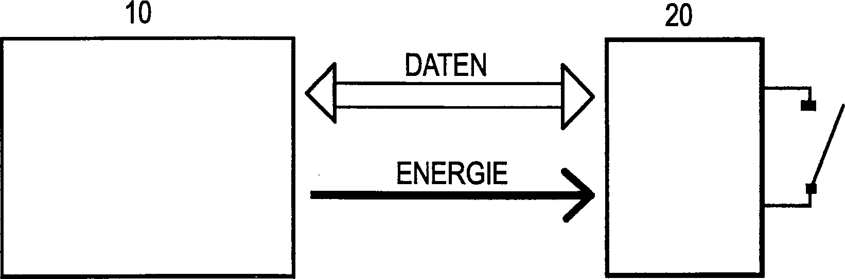
Bedienungssystem für Flurförderfahrzeuge umfassend eine Bedienungseinrichtung (10) zum Veranlassen von Schaltfunktionen und wenigstens eine Schalteinrichtung (20) zum Ausführen von Schaltfunktionen, wobei mittels der Bedienungseinrichtung (10) durch eine drahtlose Übertragung von Daten mittels der RFID-Methode zwischen der Bedienungseinrichtung (10), die ein Funksignale sendendes RFID-Lesegerät aufweist, und der Schalteinrichtung (20), die einen Transponder mit gespeicherten Daten aufweist, welche Daten durch das RFID-Lesegerät ausgelesen werden, eine Schalteinrichtung (20) ausgewählt und betätigt wird, wobei einzelne Schalteinrichtungen (20) durch die Bedienungseinrichtung (10) separat ausgewählt und betätigt werden und mehrere Schalteinrichtungen (20) durch die Bedienungseinrichtung (10) gemeinsam ausgewählt und betätigt werden.operating system for industrial trucks comprising an operating device (10) for initiating switching functions and at least one switching device (20) for executing Switching functions, wherein by means of the operating device (10) by a wireless transmission of data by means of the RFID method between the operating device (10), which has a radio-transmitting RFID reader, and the switching device (20) having a transponder with stored data which Data through the RFID reader be selected, a switching device (20) is selected and actuated is, wherein individual switching means (20) by the operating device (10) selected separately and pressed and a plurality of switching devices (20) by the operating device (10) selected together and pressed become.
Description
Die Erfindung betrifft allgemein ein Bedienungssystem für Flurförderfahrzeuge umfassend eine Bedienungseinrichtung zum Veranlassen von Schaltfunktionen und wenigstens eine Schalteinrichtung zum Ausführen von Schaltfunktionen. Bedienungssysteme sind an Gehäusen vorgesehen, welche zur Bedienung von elektrischen Geräten und Maschinen benötigt werden. Beispiele hierfür sind Bedienkonsolen, Bedienpulte, Lenkräder für Fahrzeuge und Deichselköpfe für Flurförderfahrzeuge.The The invention generally relates to an operating system for industrial trucks comprising an operating device for initiating switching functions and at least one switching device for performing switching functions. Operating systems are on housings provided for the operation of electrical equipment and Machines needed become. Examples of this are control panels, control panels, steering wheels for vehicles and tiller heads for industrial trucks.
Das
Dokument
In Bezug auf Bedienungssysteme für Flurförderfahrzeuge besteht der Wunsch, Schalteinrichtungen möglichst flexibel und unabhängig von der Anordnung und Ausgestaltung einer Bedienungseinrichtung in ein und an einem Gerät einbauen zu können. Der Flexibilität sind jedoch aufgrund der nötigen Verdrahtung zwischen der Bedienungseinrichtung und einer jeweiligen Schalteinrichtung Grenzen auferlegt.In Regarding operating systems for Flurförderfahrzeuge There is a desire, switching devices as flexible and independent of the arrangement and design of an operating device in a and on a device to be able to install. The flexibility However, due to the necessary wiring between the operating device and a respective switching device Imposes limits.
Es ist somit eine Aufgabe der Erfindung, ein Bedienungssystem für Flurförderfahrzeuge zur Verfügung zu stellen, bei welchem jeweilige Schalteinrichtungen möglichst unabhängig von der Positionierung der Bedienungseinrichtung an einem Gerät angeordnet werden können.It is therefore an object of the invention, an operating system for industrial trucks to disposal to ask, in which respective switching devices possible independently arranged by the positioning of the operating device to a device can be.
Diese Aufgabe wird erfindungsgemäß durch das im Anspruch 1 angegebene Bedienungssystem für Flurförderfahrzeuge gelöst. Die abhängigen Ansprüche 2 bis 11 zeigen spezielle Ausführungsformen des Bedienungssystems für Flurförderfahrzeuge gemäß Anspruch 1.These The object is achieved by the dissolved in claim 1 operating system for industrial trucks. The dependent claims FIGS. 2 to 11 show specific embodiments of the invention Operating system for Flurförderfahrzeuge according to claim 1.
Bei dem erfindungsgemäßen Bedienungssystem für Flurförderfahrzeuge wird insbesondere mittels der Bedienungseinrichtung durch eine drahtlose Übertragung von Daten zwischen der Bedienungseinrichtung und der Schalteinrichtung eine Schalteinrichtung ausgewählt und betätigt.at the operating system according to the invention for industrial trucks is in particular by means of the operating device by a wireless transmission data between the operating device and the switching device a switching device selected and pressed.
Durch die erfindungsgemäße drahtlose Übertragung von Daten zwischen einer Bedienungseinrichtung und einer Schalteinrichtung wird es möglich, Schalteinrichtungen auch an unzugänglichen Stellen an einem Gerät oder einer Maschine einzubauen, an welchen dies bislang aufgrund der nötigen Verdrahtung nicht möglich war. Weiterhin wird eine größere Flexibilität erreicht, weil Schalteinrichtungen bezüglich des Orts unabhängiger als bisher von Bedienungseinrichtungen eingesetzt werden können.By the wireless transmission according to the invention of data between an operating device and a switching device will it be possible Switching devices also in inaccessible places on a device or a Machine to which this so far due to the necessary wiring not possible was. Furthermore, greater flexibility is achieved because switching devices re of the place more independent as previously used by operating equipment.
Die drahtlose Übertragung von Daten erfolgt vorzugsweise mittels der RFID-(Radio Frequency Identification)-Methode, welches eine Methode ist, um Daten berührungslos und ohne Sichtkontakt zu lesen und zu speichern.The wireless transmission data is preferably obtained by means of the RFID (Radio Frequency Identification) method, which is a method for data contactless and without visual contact to read and save.
Dabei weist die Bedienungseinrichtung vorzugsweise ein Funksignale sendendes RFID-Lesegerät auf und weist die wenigstens eine Schalteinrichtung jeweils einen Transponder mit gespeicherten Daten auf, welche Daten durch das RFID-Lesegerät ausgelesen werden.there the operating device preferably has a radio signal transmitting RFID reader and the at least one switching device has one each Transponder with stored data on what data through the RFID reader be read out.
Die als Transponder ausgebildete Schalteinrichtung weist vorzugsweise einen Transponderchip mit einem Codeträger mit einem einer jeweiligen Schalteinrichtung zugeordneten Code als gespeicherte Daten auf, der zur Betätigung einer vorbestimmten Schalteinrichtung durch das als Bedienungseinrichtung ausgebildete RFID-Lesegerät erkannt und ausgewertet wird. Der Transponderchip weist weiterhin vorzugsweise einen Resonanzkreis auf, der wiederum eine Parallelschaltung aus einer Spule und einem Kondensator aufweist, wobei die Spule des Transponderchips und eine Spule (bzw. Antenne) des RFID-Lesegeräts induktiv koppelbar sind.The designed as a transponder switching device preferably has a transponder chip with a code carrier with one of a respective switching device associated code as stored data, which is used to actuate a predetermined switching device by as the operating device trained RFID reader is recognized and evaluated. The transponder chip continues to point Preferably, a resonant circuit, in turn, a parallel circuit comprising a coil and a capacitor, wherein the coil of the transponder chip and a coil (or antenna) of the RFID reader inductively can be coupled.
Der Transponder kann als passiver Transponder ausgebildet sein, der seine Versorgungsspannung durch die induktive Kopplung aus Funksignalen des RFID-Lesegeräts gewinnt, wodurch die als Transponder ausgebildete Schalteinrichtung nicht eigens mit Energie versorgt werden muss und somit auch keine Anschlussdrähte zur Energieversorgung benötigt.Of the Transponder can be designed as a passive transponder, the its supply voltage through the inductive coupling of radio signals of the RFID reader wins, making the trained as a transponder switching device does not need to be specially supplied with energy and thus no leads needed for energy supply.
Die Schalteinrichtung kann ein als Taster oder Schalter ausgelegtes elektromechanisches Bauteil mit Schließer- oder Öffnerfunktion aufweisen. Sie kann aber auch einen Proportionaltaster aufweisen, in welchem Fall der Transponderchip weiterhin einen zum Resonanzkreis parallel geschalteten veränderbaren Widerstand aufweist und/oder die Spule veränderbar ist und/oder der Kondensator veränderbar ist. Die Schalteinrichtung kann somit verschiedenste Schalter umfassen, so dass das erfindungsgemäße Bedienungssystem auch bei komplexen Maschinen mit vielen und verschieden Schaltern und Tastern vorteilhaft eingesetzt werden kann.The Switching device can be designed as a button or switch Have electromechanical component with NO or NC function. she but may also have a proportioning, in which case the transponder chip continues to be connected in parallel to the resonant circuit changeable Resistor and / or the coil is variable and / or the capacitor variable is. The switching device may thus comprise a variety of switches, so that the operating system according to the invention even with complex machines with many and different switches and buttons can be used advantageously.
Im Fall eines Proportionaltasters als Schalteinrichtung wird eine durch einen bestimmten zurückgelegten Weg des Proportionaltasters hervorgerufene Änderung als Analogwert durch eine Veränderung der Lastmodulation durch den Widerstand oder durch eine Veränderung der Resonanzfrequenz des Resonanzkreises erkannt und ausgewertet.In the case of a proportional switch as a switching device is one by a certain traveled distance of the Proportionaltasters caused change as analog value detected by a change in the load modulation by the resistance or by a change in the resonant frequency of the resonant circuit and evaluated.
Weiterhin kann der Transponder Informationen in Klartext oder als verschlüsselte Daten senden. In einem Frequenzbereich von 13,56 MHz ist eine schnelle Datenübertragung realisierbar und ist der Einsatz von Signalverschlüsselungsverfahren möglich. In einem Frequenzbereich zwischen 9 kHz und 135 kHz kann eine Spule mit Ferritkern als die Spule des Resonanzkreises verwendet werden, so dass eine Miniaturisierung des Transponders möglich wird.Farther The transponder can display information in plain text or as encrypted data send. In a frequency range of 13.56 MHz is a fast data transfer feasible and is the use of signal encryption techniques possible. In a frequency range between 9 kHz and 135 kHz can be a coil be used with ferrite core as the coil of the resonant circuit, so that a miniaturization of the transponder is possible.
Die einzelnen Schalteinrichtungen können durch das Lesegerät der Bedienungseinrichtung separat ausgelesen werden und/oder mehrere Schalteinrichtungen können gemeinsam in einer so genannten Pulklesung ausgelesen werden.The individual switching devices can through the reader the operating device are read out separately and / or several Switching devices can be read together in a so-called Pulklesung.
Das erfindungsgemäße Bedienungssystem kann vorzugsweise in Gehäusen verwendet werden, wie im Fall von Bedienkonsolen, Bedienpulten, Lenkrädern für Fahrzeuge und/oder Deichselköpfen für Flurförderfahrzeuge.The inventive operating system can preferably in housings used, as in the case of control panels, control panels, steering wheels for vehicles and / or tiller heads for industrial trucks.
Die angegebenen und weitere Merkmale und Einzelheiten der Erfindung werden einem Fachmann auf dem Gebiet aus der folgenden detaillierten Beschreibung und der beigefügten Zeichnung klarer, die Merkmale der vorliegenden Erfindung anhand eines Beispiels darstellt und wobei:The specified and other features and details of the invention will be apparent to one skilled in the art from the following detailed Description and attached Drawing clearer, the features of the present invention with reference an example and wherein:
Im Folgenden wird die vorliegende Erfindung anhand einer bevorzugten Ausführungsform unter Bezugnahme auf die beigefügte Zeichnung detailliert erklärt.in the Below, the present invention is based on a preferred embodiment with reference to the attached Detailed explanation of the drawing.
Die meisten Transponder senden Informationen im Klartext. Es gibt aber auch Transponder, bei denen eine Übertragung verschlüsselter Daten möglich ist. Bei dem Bedienungssystem gemäß der vorliegenden Erfindung können beide Möglichkeiten verwendet werden.The Most transponders send information in plain text. But there is also transponders where a transmission is encrypted Data possible is. In the operating system according to the present invention can both possibilities be used.
Gemäß der Erfindung ist weiterhin ein Arbeiten in den folgenden Frequenzbereichen mit jeweiligen Vorteilen möglich.According to the invention is still working in the following frequency ranges respective advantages possible.
Im Frequenzbereich von 9 kHz bis 135 kHz liegen die Trägerfrequenzen von RFID-Systemen im Allgemeinen zwischen 120 kHz und 135 kHz. Durch die Verwendung von Spulen mit Ferritkern ist eine miniaturisierte Bauform für den Transponder möglich. In diesem Bereich können passive Transponder eingesetzt werden.in the Frequency range from 9 kHz to 135 kHz are the carrier frequencies of RFID systems generally between 120 kHz and 135 kHz. By the Use of coils with ferrite core is a miniaturized design for the Transponder possible. In this area can passive transponders are used.
Bei einer Frequenz von 13,56 MHz gibt es den Vorteil, dass eine schnelle Datenübertragung von typischerweise 106 kBits/s realisierbar ist. Aufgrund der hohen Taktfrequenz ist der Einsatz von Signalverschlüsselungsverfahren möglich.at A frequency of 13.56 MHz gives it the advantage of being a fast Data transfer from typically 106 kBits / s is feasible. Because of the high Clock frequency is the use of signal encryption method possible.
Weiterhin
sind einige RFID-Lesegeräte
in der Lage, spezielle Transponder stapelweise lesen zu können, was
Pulklesung genannt wird. Das bedeutet, dass bei den Schaltern und
Tastern durch die Bedienungseinrichtung
Im
Folgenden wird die mit einem Transponder ausgebildete Schalteinrichtung
Die
Wenn
die als RFID-Lesegerät
ausgebildete Bedienungseinrichtung
Gleichzeitig damit kann auch die Übertragung von Energie durch die schon angegebene induktive Kopplung erfolgen, wobei die Voraussetzungen erfüllt sein müssen, dass der Transponder ein kleiner passiver Transponder, d. h. ohne Batterie, ist und dass die Wellenlänge der Betriebsfrequenz sehr viel kleiner als die Entfernung zwischen dem Lesegerät und dem Transponder ist, was bedeutet, dass ein Arbeiten im Nahfeld einer Antenne (des Lesegeräts) erfolgt. Unmittelbar an der Antenne wird ein magnetisches Feld erzeugt, welches elektrische Feldlinien in den Raum induziert und somit Energie zum Transponder leitet.simultaneously so can the transmission of energy through the already indicated inductive coupling, meeting the requirements have to be that the transponder is a small passive transponder, d. H. without Battery is very high, and that the operating frequency of the wave is less than the distance between the reader and the transponder, which means working in the near field of an antenna (the reader). Immediately to the antenna, a magnetic field is generated, which induced electric field lines in the room and thus energy for Transponder directs.
Nun
wird unter Bezugnahme auf die
Die
Funktion des Proportionaltasters
Diese Änderung kann beispielsweise eine Änderung der Lastmodulation sein. Da der Abstand vom Transponder zum Lesegerät im eingebauten Zustand des Bedienungssystems immer gleich ist, kann die Amplitudenhöhe ausgewertet werden. Je größer die Belastung durch den Widerstand R entsprechend einer Amplitudenänderung ist, umso mehr verändert sich der Analogwert, welcher vom Lesegerät berechnet wird.This change for example, a change be the load modulation. Since the distance from the transponder to the reader is built in State of the operating system is always the same, the amplitude level can be evaluated become. The bigger the Load through the resistor R according to a change in amplitude is, the more it changes the analog value, which is calculated by the reader.
Es ist auch möglich, den Strom zu messen, da bei dieser Modulationsart (Lastmodulation) die Resonanzfrequenz des Transponders auf die Sendefrequenz des Lesegeräts abgestimmt ist. Sobald ein Transponder in das magnetische Wechselfeld eines Lesegeräts gelangt, gerät er in Resonanz. Dies bewirkt, dass dem Feld keine zusätzliche Energie entzogen wird. Über den Speisestrom der Antenne des Lesegeräts kann die zusätzlich entnommene Energie ermittelt werden. Die Änderung des Stroms entspricht somit einer Änderung des Analogwerts.It is possible, too, measure the current, since with this type of modulation (load modulation) the resonance frequency of the transponder on the transmission frequency of the reader is tuned. As soon as a transponder enters the magnetic alternating field a reader arrives. device he resonates. This causes the field no additional Energy is withdrawn. about the supply current of the antenna of the reader, the additionally removed Energy to be determined. The change of the current thus corresponds to a change in the analog value.
Die Änderung kann aber auch eine Änderung der Resonanzfrequenz sein. Zur Analogwerterkennung kann die Resonanzfrequenz des Resonanzkreises verändert werden. Dies erfolgt durch Änderung des variablen Kondensators C oder der variablen Spule L. Dabei wird die Änderung der Spule L bevorzugt, was durch einen Kern erfolgt, der in das Innere der Spule geschoben wird, wodurch eine Änderung der Resonanzfrequenz auf einfache Weise hervorgerufen werden kann. Der Analogwert wird dann über die Auswertung der Resonanzfrequenzdifferenz ermittelt.The change but also a change of Be resonant frequency. For analog value detection, the resonance frequency the resonant circuit changed become. This is done by changing the variable capacitor C or the variable coil L. In doing so the change the coil L is preferred, which is done by a core in the Inside the coil is pushed, causing a change in the resonant frequency can be easily generated. The analog value is then about the Evaluation of the resonance frequency difference determined.
Gemäß der erfindungsgemäßen Ausgestaltung
eines Bedienungssystems können
folgende Vorteile erzielt werden:
Durch eine drahtlose Übertragung
von Daten zwischen einer Bedienungseinrichtung und einer Schalteinrichtung
wird ein hohes Maß an
Flexibilität
erreicht. Fehler aufgrund von Kabelbruch können ausgeschlossen werden.According to the embodiment of an operating system according to the invention, the following advantages can be achieved:
By a wireless transmission of data between an operating device and a switching device, a high degree of flexibility is achieved. Errors due to cable breakage can be excluded.
Beim Einsatz von passiven Transpondern erfolgt die Energieversorgung durch induktive Kopplung des Transponders und des Lesegeräts, so dass keine Batterie für den Transponder nötig ist.At the Use of passive transponders is the power supply by inductive coupling of the transponder and the reader, so no Battery for the transponder needed is.
Die Transponder können Informationen im Klartext und als verschlüsselte Daten übertragen.The Transponders can Information in plain text and transmitted as encrypted data.
Ein Einsatz von Transpondern ist für viele Arten von Schaltern und Tastern möglich.One Use of transponders is for many types of switches and buttons possible.
Die einzelnen Transponder können durch das Lesegerät separat ausgelesen werden und/oder mehrere Transponder können gemeinsam in einer so genannten Pulklesung ausgelesen werden.The individual transponder can through the reader can be read out separately and / or multiple transponders can be shared be read in a so-called Pulklesung.
Das erfindungsgemäße Bedienungssystem ist besonders vorteilhaft bei Fahrzeugen und Flurförderfahrzeugen einsetzbar, bei welchen viele Schalteinrichtungen mittels einer Bedienungseinrichtung auszuwählen und zu betätigen sind.The inventive operating system is particularly advantageous for use in vehicles and industrial trucks, in which many switching devices to select by means of an operating device and to press are.
Claims (11)
Priority Applications (1)
| Application Number | Priority Date | Filing Date | Title |
|---|---|---|---|
| DE102005036290A DE102005036290B4 (en) | 2005-08-02 | 2005-08-02 | operating system |
Applications Claiming Priority (1)
| Application Number | Priority Date | Filing Date | Title |
|---|---|---|---|
| DE102005036290A DE102005036290B4 (en) | 2005-08-02 | 2005-08-02 | operating system |
Publications (2)
| Publication Number | Publication Date |
|---|---|
| DE102005036290A1 DE102005036290A1 (en) | 2007-02-15 |
| DE102005036290B4 true DE102005036290B4 (en) | 2009-04-30 |
Family
ID=37680852
Family Applications (1)
| Application Number | Title | Priority Date | Filing Date |
|---|---|---|---|
| DE102005036290A Expired - Fee Related DE102005036290B4 (en) | 2005-08-02 | 2005-08-02 | operating system |
Country Status (1)
| Country | Link |
|---|---|
| DE (1) | DE102005036290B4 (en) |
Cited By (45)
| Publication number | Priority date | Publication date | Assignee | Title |
|---|---|---|---|---|
| US7741734B2 (en) | 2005-07-12 | 2010-06-22 | Massachusetts Institute Of Technology | Wireless non-radiative energy transfer |
| US7825543B2 (en) | 2005-07-12 | 2010-11-02 | Massachusetts Institute Of Technology | Wireless energy transfer |
| US8035255B2 (en) | 2008-09-27 | 2011-10-11 | Witricity Corporation | Wireless energy transfer using planar capacitively loaded conducting loop resonators |
| US8076801B2 (en) | 2008-05-14 | 2011-12-13 | Massachusetts Institute Of Technology | Wireless energy transfer, including interference enhancement |
| US8304935B2 (en) | 2008-09-27 | 2012-11-06 | Witricity Corporation | Wireless energy transfer using field shaping to reduce loss |
| US8324759B2 (en) | 2008-09-27 | 2012-12-04 | Witricity Corporation | Wireless energy transfer using magnetic materials to shape field and reduce loss |
| US8362651B2 (en) | 2008-10-01 | 2013-01-29 | Massachusetts Institute Of Technology | Efficient near-field wireless energy transfer using adiabatic system variations |
| US8400017B2 (en) | 2008-09-27 | 2013-03-19 | Witricity Corporation | Wireless energy transfer for computer peripheral applications |
| US8410636B2 (en) | 2008-09-27 | 2013-04-02 | Witricity Corporation | Low AC resistance conductor designs |
| US8461721B2 (en) | 2008-09-27 | 2013-06-11 | Witricity Corporation | Wireless energy transfer using object positioning for low loss |
| US8461720B2 (en) | 2008-09-27 | 2013-06-11 | Witricity Corporation | Wireless energy transfer using conducting surfaces to shape fields and reduce loss |
| US8461722B2 (en) | 2008-09-27 | 2013-06-11 | Witricity Corporation | Wireless energy transfer using conducting surfaces to shape field and improve K |
| US8471410B2 (en) | 2008-09-27 | 2013-06-25 | Witricity Corporation | Wireless energy transfer over distance using field shaping to improve the coupling factor |
| US8476788B2 (en) | 2008-09-27 | 2013-07-02 | Witricity Corporation | Wireless energy transfer with high-Q resonators using field shaping to improve K |
| US8482158B2 (en) | 2008-09-27 | 2013-07-09 | Witricity Corporation | Wireless energy transfer using variable size resonators and system monitoring |
| US8487480B1 (en) | 2008-09-27 | 2013-07-16 | Witricity Corporation | Wireless energy transfer resonator kit |
| US8497601B2 (en) | 2008-09-27 | 2013-07-30 | Witricity Corporation | Wireless energy transfer converters |
| US8552592B2 (en) | 2008-09-27 | 2013-10-08 | Witricity Corporation | Wireless energy transfer with feedback control for lighting applications |
| US8569914B2 (en) | 2008-09-27 | 2013-10-29 | Witricity Corporation | Wireless energy transfer using object positioning for improved k |
| US8587155B2 (en) | 2008-09-27 | 2013-11-19 | Witricity Corporation | Wireless energy transfer using repeater resonators |
| US8587153B2 (en) | 2008-09-27 | 2013-11-19 | Witricity Corporation | Wireless energy transfer using high Q resonators for lighting applications |
| US8598743B2 (en) | 2008-09-27 | 2013-12-03 | Witricity Corporation | Resonator arrays for wireless energy transfer |
| US8643326B2 (en) | 2008-09-27 | 2014-02-04 | Witricity Corporation | Tunable wireless energy transfer systems |
| US8669676B2 (en) | 2008-09-27 | 2014-03-11 | Witricity Corporation | Wireless energy transfer across variable distances using field shaping with magnetic materials to improve the coupling factor |
| US8686598B2 (en) | 2008-09-27 | 2014-04-01 | Witricity Corporation | Wireless energy transfer for supplying power and heat to a device |
| US8692410B2 (en) | 2008-09-27 | 2014-04-08 | Witricity Corporation | Wireless energy transfer with frequency hopping |
| US8692412B2 (en) | 2008-09-27 | 2014-04-08 | Witricity Corporation | Temperature compensation in a wireless transfer system |
| US8723366B2 (en) | 2008-09-27 | 2014-05-13 | Witricity Corporation | Wireless energy transfer resonator enclosures |
| US8772973B2 (en) | 2008-09-27 | 2014-07-08 | Witricity Corporation | Integrated resonator-shield structures |
| US8847548B2 (en) | 2008-09-27 | 2014-09-30 | Witricity Corporation | Wireless energy transfer for implantable devices |
| US8937408B2 (en) | 2008-09-27 | 2015-01-20 | Witricity Corporation | Wireless energy transfer for medical applications |
| US8947186B2 (en) | 2008-09-27 | 2015-02-03 | Witricity Corporation | Wireless energy transfer resonator thermal management |
| US9184595B2 (en) | 2008-09-27 | 2015-11-10 | Witricity Corporation | Wireless energy transfer in lossy environments |
| US9318898B2 (en) | 2007-06-01 | 2016-04-19 | Witricity Corporation | Wireless power harvesting and transmission with heterogeneous signals |
| US9396867B2 (en) | 2008-09-27 | 2016-07-19 | Witricity Corporation | Integrated resonator-shield structures |
| US9404954B2 (en) | 2012-10-19 | 2016-08-02 | Witricity Corporation | Foreign object detection in wireless energy transfer systems |
| US9421388B2 (en) | 2007-06-01 | 2016-08-23 | Witricity Corporation | Power generation for implantable devices |
| US9449757B2 (en) | 2012-11-16 | 2016-09-20 | Witricity Corporation | Systems and methods for wireless power system with improved performance and/or ease of use |
| US9544683B2 (en) | 2008-09-27 | 2017-01-10 | Witricity Corporation | Wirelessly powered audio devices |
| US9601270B2 (en) | 2008-09-27 | 2017-03-21 | Witricity Corporation | Low AC resistance conductor designs |
| US9601261B2 (en) | 2008-09-27 | 2017-03-21 | Witricity Corporation | Wireless energy transfer using repeater resonators |
| US9601266B2 (en) | 2008-09-27 | 2017-03-21 | Witricity Corporation | Multiple connected resonators with a single electronic circuit |
| US9602168B2 (en) | 2010-08-31 | 2017-03-21 | Witricity Corporation | Communication in wireless energy transfer systems |
| US9698607B2 (en) | 2008-09-27 | 2017-07-04 | Witricity Corporation | Secure wireless energy transfer |
| US11958370B2 (en) | 2021-08-31 | 2024-04-16 | Witricity Corporation | Wireless power system modules |
Families Citing this family (59)
| Publication number | Priority date | Publication date | Assignee | Title |
|---|---|---|---|---|
| KR101695169B1 (en) * | 2007-03-27 | 2017-01-11 | 메사추세츠 인스티튜트 오브 테크놀로지 | Wireless energy transfer |
| DE102007019339B4 (en) * | 2007-04-24 | 2009-12-17 | Siemens Ag | Arrangement for monitoring a switching state of a switch |
| US8901778B2 (en) | 2008-09-27 | 2014-12-02 | Witricity Corporation | Wireless energy transfer with variable size resonators for implanted medical devices |
| US8441154B2 (en) | 2008-09-27 | 2013-05-14 | Witricity Corporation | Multi-resonator wireless energy transfer for exterior lighting |
| US8946938B2 (en) | 2008-09-27 | 2015-02-03 | Witricity Corporation | Safety systems for wireless energy transfer in vehicle applications |
| US9160203B2 (en) | 2008-09-27 | 2015-10-13 | Witricity Corporation | Wireless powered television |
| US9106203B2 (en) | 2008-09-27 | 2015-08-11 | Witricity Corporation | Secure wireless energy transfer in medical applications |
| US8466583B2 (en) | 2008-09-27 | 2013-06-18 | Witricity Corporation | Tunable wireless energy transfer for outdoor lighting applications |
| US9744858B2 (en) | 2008-09-27 | 2017-08-29 | Witricity Corporation | System for wireless energy distribution in a vehicle |
| US8933594B2 (en) | 2008-09-27 | 2015-01-13 | Witricity Corporation | Wireless energy transfer for vehicles |
| US9035499B2 (en) | 2008-09-27 | 2015-05-19 | Witricity Corporation | Wireless energy transfer for photovoltaic panels |
| US8907531B2 (en) | 2008-09-27 | 2014-12-09 | Witricity Corporation | Wireless energy transfer with variable size resonators for medical applications |
| US9318922B2 (en) | 2008-09-27 | 2016-04-19 | Witricity Corporation | Mechanically removable wireless power vehicle seat assembly |
| US9065423B2 (en) | 2008-09-27 | 2015-06-23 | Witricity Corporation | Wireless energy distribution system |
| US8963488B2 (en) | 2008-09-27 | 2015-02-24 | Witricity Corporation | Position insensitive wireless charging |
| US9246336B2 (en) | 2008-09-27 | 2016-01-26 | Witricity Corporation | Resonator optimizations for wireless energy transfer |
| US8957549B2 (en) | 2008-09-27 | 2015-02-17 | Witricity Corporation | Tunable wireless energy transfer for in-vehicle applications |
| US8629578B2 (en) | 2008-09-27 | 2014-01-14 | Witricity Corporation | Wireless energy transfer systems |
| US9093853B2 (en) | 2008-09-27 | 2015-07-28 | Witricity Corporation | Flexible resonator attachment |
| US8901779B2 (en) | 2008-09-27 | 2014-12-02 | Witricity Corporation | Wireless energy transfer with resonator arrays for medical applications |
| US9105959B2 (en) | 2008-09-27 | 2015-08-11 | Witricity Corporation | Resonator enclosure |
| US9515494B2 (en) | 2008-09-27 | 2016-12-06 | Witricity Corporation | Wireless power system including impedance matching network |
| US8928276B2 (en) | 2008-09-27 | 2015-01-06 | Witricity Corporation | Integrated repeaters for cell phone applications |
| US8922066B2 (en) | 2008-09-27 | 2014-12-30 | Witricity Corporation | Wireless energy transfer with multi resonator arrays for vehicle applications |
| US9948145B2 (en) | 2011-07-08 | 2018-04-17 | Witricity Corporation | Wireless power transfer for a seat-vest-helmet system |
| CA2844062C (en) | 2011-08-04 | 2017-03-28 | Witricity Corporation | Tunable wireless power architectures |
| WO2013036947A2 (en) | 2011-09-09 | 2013-03-14 | Witricity Corporation | Foreign object detection in wireless energy transfer systems |
| US20130062966A1 (en) | 2011-09-12 | 2013-03-14 | Witricity Corporation | Reconfigurable control architectures and algorithms for electric vehicle wireless energy transfer systems |
| US9318257B2 (en) | 2011-10-18 | 2016-04-19 | Witricity Corporation | Wireless energy transfer for packaging |
| AU2012332131A1 (en) | 2011-11-04 | 2014-05-22 | Witricity Corporation | Wireless energy transfer modeling tool |
| JP2015508987A (en) | 2012-01-26 | 2015-03-23 | ワイトリシティ コーポレーションWitricity Corporation | Wireless energy transmission with reduced field |
| US9343922B2 (en) | 2012-06-27 | 2016-05-17 | Witricity Corporation | Wireless energy transfer for rechargeable batteries |
| US9287607B2 (en) | 2012-07-31 | 2016-03-15 | Witricity Corporation | Resonator fine tuning |
| US9595378B2 (en) | 2012-09-19 | 2017-03-14 | Witricity Corporation | Resonator enclosure |
| JP2016534698A (en) | 2013-08-14 | 2016-11-04 | ワイトリシティ コーポレーションWitricity Corporation | Impedance tuning |
| US9780573B2 (en) | 2014-02-03 | 2017-10-03 | Witricity Corporation | Wirelessly charged battery system |
| WO2015123614A2 (en) | 2014-02-14 | 2015-08-20 | Witricity Corporation | Object detection for wireless energy transfer systems |
| US9842687B2 (en) | 2014-04-17 | 2017-12-12 | Witricity Corporation | Wireless power transfer systems with shaped magnetic components |
| WO2015161035A1 (en) | 2014-04-17 | 2015-10-22 | Witricity Corporation | Wireless power transfer systems with shield openings |
| US9837860B2 (en) | 2014-05-05 | 2017-12-05 | Witricity Corporation | Wireless power transmission systems for elevators |
| EP3140680B1 (en) | 2014-05-07 | 2021-04-21 | WiTricity Corporation | Foreign object detection in wireless energy transfer systems |
| US9829305B2 (en) | 2014-05-14 | 2017-11-28 | Faro Technologies, Inc. | Metrology device and method of changing operating system |
| US9803969B2 (en) | 2014-05-14 | 2017-10-31 | Faro Technologies, Inc. | Metrology device and method of communicating with portable devices |
| US9739591B2 (en) | 2014-05-14 | 2017-08-22 | Faro Technologies, Inc. | Metrology device and method of initiating communication |
| US9903701B2 (en) * | 2014-05-14 | 2018-02-27 | Faro Technologies, Inc. | Articulated arm coordinate measurement machine having a rotary switch |
| US9746308B2 (en) | 2014-05-14 | 2017-08-29 | Faro Technologies, Inc. | Metrology device and method of performing an inspection |
| US9921046B2 (en) | 2014-05-14 | 2018-03-20 | Faro Technologies, Inc. | Metrology device and method of servicing |
| US9954375B2 (en) | 2014-06-20 | 2018-04-24 | Witricity Corporation | Wireless power transfer systems for surfaces |
| US10574091B2 (en) | 2014-07-08 | 2020-02-25 | Witricity Corporation | Enclosures for high power wireless power transfer systems |
| US9842688B2 (en) | 2014-07-08 | 2017-12-12 | Witricity Corporation | Resonator balancing in wireless power transfer systems |
| US9843217B2 (en) | 2015-01-05 | 2017-12-12 | Witricity Corporation | Wireless energy transfer for wearables |
| US10248899B2 (en) | 2015-10-06 | 2019-04-02 | Witricity Corporation | RFID tag and transponder detection in wireless energy transfer systems |
| EP3362804B1 (en) | 2015-10-14 | 2024-01-17 | WiTricity Corporation | Phase and amplitude detection in wireless energy transfer systems |
| WO2017070227A1 (en) | 2015-10-19 | 2017-04-27 | Witricity Corporation | Foreign object detection in wireless energy transfer systems |
| EP3365958B1 (en) | 2015-10-22 | 2020-05-27 | WiTricity Corporation | Dynamic tuning in wireless energy transfer systems |
| US10075019B2 (en) | 2015-11-20 | 2018-09-11 | Witricity Corporation | Voltage source isolation in wireless power transfer systems |
| US10263473B2 (en) | 2016-02-02 | 2019-04-16 | Witricity Corporation | Controlling wireless power transfer systems |
| US10063104B2 (en) | 2016-02-08 | 2018-08-28 | Witricity Corporation | PWM capacitor control |
| WO2019006376A1 (en) | 2017-06-29 | 2019-01-03 | Witricity Corporation | Protection and control of wireless power systems |
Citations (6)
| Publication number | Priority date | Publication date | Assignee | Title |
|---|---|---|---|---|
| EP0744627A1 (en) * | 1995-05-25 | 1996-11-27 | Palomar Technologies Corporation | Transponder system for the remote communication of a physical condition |
| DE19711788A1 (en) * | 1997-03-21 | 1998-09-24 | Bosch Gmbh Robert | Device for influencing the operating state of an electronic device |
| EP0877333A2 (en) * | 1997-05-09 | 1998-11-11 | Anatoli Stobbe | Apparatus for wireless transfer of energy and execution of an action |
| WO2002059851A1 (en) * | 2001-01-25 | 2002-08-01 | BSH Bosch und Siemens Hausgeräte GmbH | Electric domestic appliance comprising a communication interface |
| DE10237832A1 (en) * | 2002-08-09 | 2004-10-07 | Michael Hartung | Smart card as near range remote control replacing control panel of technical devices |
| DE102005013063A1 (en) * | 2004-03-31 | 2005-11-03 | Carl Zeiss Meditec Ag | Wireless operation microscope control procedure uses separate control unit with wireless power supply |
-
2005
- 2005-08-02 DE DE102005036290A patent/DE102005036290B4/en not_active Expired - Fee Related
Patent Citations (6)
| Publication number | Priority date | Publication date | Assignee | Title |
|---|---|---|---|---|
| EP0744627A1 (en) * | 1995-05-25 | 1996-11-27 | Palomar Technologies Corporation | Transponder system for the remote communication of a physical condition |
| DE19711788A1 (en) * | 1997-03-21 | 1998-09-24 | Bosch Gmbh Robert | Device for influencing the operating state of an electronic device |
| EP0877333A2 (en) * | 1997-05-09 | 1998-11-11 | Anatoli Stobbe | Apparatus for wireless transfer of energy and execution of an action |
| WO2002059851A1 (en) * | 2001-01-25 | 2002-08-01 | BSH Bosch und Siemens Hausgeräte GmbH | Electric domestic appliance comprising a communication interface |
| DE10237832A1 (en) * | 2002-08-09 | 2004-10-07 | Michael Hartung | Smart card as near range remote control replacing control panel of technical devices |
| DE102005013063A1 (en) * | 2004-03-31 | 2005-11-03 | Carl Zeiss Meditec Ag | Wireless operation microscope control procedure uses separate control unit with wireless power supply |
Cited By (67)
| Publication number | Priority date | Publication date | Assignee | Title |
|---|---|---|---|---|
| US7741734B2 (en) | 2005-07-12 | 2010-06-22 | Massachusetts Institute Of Technology | Wireless non-radiative energy transfer |
| US9065286B2 (en) | 2005-07-12 | 2015-06-23 | Massachusetts Institute Of Technology | Wireless non-radiative energy transfer |
| US8022576B2 (en) | 2005-07-12 | 2011-09-20 | Massachusetts Institute Of Technology | Wireless non-radiative energy transfer |
| US9509147B2 (en) | 2005-07-12 | 2016-11-29 | Massachusetts Institute Of Technology | Wireless energy transfer |
| US8076800B2 (en) | 2005-07-12 | 2011-12-13 | Massachusetts Institute Of Technology | Wireless non-radiative energy transfer |
| US8766485B2 (en) | 2005-07-12 | 2014-07-01 | Massachusetts Institute Of Technology | Wireless energy transfer over distances to a moving device |
| US8084889B2 (en) | 2005-07-12 | 2011-12-27 | Massachusetts Institute Of Technology | Wireless non-radiative energy transfer |
| US8772971B2 (en) | 2005-07-12 | 2014-07-08 | Massachusetts Institute Of Technology | Wireless energy transfer across variable distances with high-Q capacitively-loaded conducting-wire loops |
| US8791599B2 (en) | 2005-07-12 | 2014-07-29 | Massachusetts Institute Of Technology | Wireless energy transfer to a moving device between high-Q resonators |
| US7825543B2 (en) | 2005-07-12 | 2010-11-02 | Massachusetts Institute Of Technology | Wireless energy transfer |
| US8097983B2 (en) | 2005-07-12 | 2012-01-17 | Massachusetts Institute Of Technology | Wireless energy transfer |
| US8772972B2 (en) | 2005-07-12 | 2014-07-08 | Massachusetts Institute Of Technology | Wireless energy transfer across a distance to a moving device |
| US8395283B2 (en) | 2005-07-12 | 2013-03-12 | Massachusetts Institute Of Technology | Wireless energy transfer over a distance at high efficiency |
| US8400018B2 (en) | 2005-07-12 | 2013-03-19 | Massachusetts Institute Of Technology | Wireless energy transfer with high-Q at high efficiency |
| US8400019B2 (en) | 2005-07-12 | 2013-03-19 | Massachusetts Institute Of Technology | Wireless energy transfer with high-Q from more than one source |
| US8400022B2 (en) | 2005-07-12 | 2013-03-19 | Massachusetts Institute Of Technology | Wireless energy transfer with high-Q similar resonant frequency resonators |
| US8400024B2 (en) | 2005-07-12 | 2013-03-19 | Massachusetts Institute Of Technology | Wireless energy transfer across variable distances |
| US9444265B2 (en) | 2005-07-12 | 2016-09-13 | Massachusetts Institute Of Technology | Wireless energy transfer |
| US8400023B2 (en) | 2005-07-12 | 2013-03-19 | Massachusetts Institute Of Technology | Wireless energy transfer with high-Q capacitively loaded conducting loops |
| US9450421B2 (en) | 2005-07-12 | 2016-09-20 | Massachusetts Institute Of Technology | Wireless non-radiative energy transfer |
| US9421388B2 (en) | 2007-06-01 | 2016-08-23 | Witricity Corporation | Power generation for implantable devices |
| US9318898B2 (en) | 2007-06-01 | 2016-04-19 | Witricity Corporation | Wireless power harvesting and transmission with heterogeneous signals |
| US8076801B2 (en) | 2008-05-14 | 2011-12-13 | Massachusetts Institute Of Technology | Wireless energy transfer, including interference enhancement |
| US8587153B2 (en) | 2008-09-27 | 2013-11-19 | Witricity Corporation | Wireless energy transfer using high Q resonators for lighting applications |
| US8410636B2 (en) | 2008-09-27 | 2013-04-02 | Witricity Corporation | Low AC resistance conductor designs |
| US8476788B2 (en) | 2008-09-27 | 2013-07-02 | Witricity Corporation | Wireless energy transfer with high-Q resonators using field shaping to improve K |
| US8482158B2 (en) | 2008-09-27 | 2013-07-09 | Witricity Corporation | Wireless energy transfer using variable size resonators and system monitoring |
| US8487480B1 (en) | 2008-09-27 | 2013-07-16 | Witricity Corporation | Wireless energy transfer resonator kit |
| US8497601B2 (en) | 2008-09-27 | 2013-07-30 | Witricity Corporation | Wireless energy transfer converters |
| US8552592B2 (en) | 2008-09-27 | 2013-10-08 | Witricity Corporation | Wireless energy transfer with feedback control for lighting applications |
| US8569914B2 (en) | 2008-09-27 | 2013-10-29 | Witricity Corporation | Wireless energy transfer using object positioning for improved k |
| US8587155B2 (en) | 2008-09-27 | 2013-11-19 | Witricity Corporation | Wireless energy transfer using repeater resonators |
| US8461719B2 (en) | 2008-09-27 | 2013-06-11 | Witricity Corporation | Wireless energy transfer systems |
| US8598743B2 (en) | 2008-09-27 | 2013-12-03 | Witricity Corporation | Resonator arrays for wireless energy transfer |
| US8643326B2 (en) | 2008-09-27 | 2014-02-04 | Witricity Corporation | Tunable wireless energy transfer systems |
| US8669676B2 (en) | 2008-09-27 | 2014-03-11 | Witricity Corporation | Wireless energy transfer across variable distances using field shaping with magnetic materials to improve the coupling factor |
| US8686598B2 (en) | 2008-09-27 | 2014-04-01 | Witricity Corporation | Wireless energy transfer for supplying power and heat to a device |
| US8692410B2 (en) | 2008-09-27 | 2014-04-08 | Witricity Corporation | Wireless energy transfer with frequency hopping |
| US8692412B2 (en) | 2008-09-27 | 2014-04-08 | Witricity Corporation | Temperature compensation in a wireless transfer system |
| US8723366B2 (en) | 2008-09-27 | 2014-05-13 | Witricity Corporation | Wireless energy transfer resonator enclosures |
| US8461722B2 (en) | 2008-09-27 | 2013-06-11 | Witricity Corporation | Wireless energy transfer using conducting surfaces to shape field and improve K |
| US8461720B2 (en) | 2008-09-27 | 2013-06-11 | Witricity Corporation | Wireless energy transfer using conducting surfaces to shape fields and reduce loss |
| US8461721B2 (en) | 2008-09-27 | 2013-06-11 | Witricity Corporation | Wireless energy transfer using object positioning for low loss |
| US8772973B2 (en) | 2008-09-27 | 2014-07-08 | Witricity Corporation | Integrated resonator-shield structures |
| US8471410B2 (en) | 2008-09-27 | 2013-06-25 | Witricity Corporation | Wireless energy transfer over distance using field shaping to improve the coupling factor |
| US8847548B2 (en) | 2008-09-27 | 2014-09-30 | Witricity Corporation | Wireless energy transfer for implantable devices |
| US8937408B2 (en) | 2008-09-27 | 2015-01-20 | Witricity Corporation | Wireless energy transfer for medical applications |
| US8947186B2 (en) | 2008-09-27 | 2015-02-03 | Witricity Corporation | Wireless energy transfer resonator thermal management |
| US8400017B2 (en) | 2008-09-27 | 2013-03-19 | Witricity Corporation | Wireless energy transfer for computer peripheral applications |
| US9184595B2 (en) | 2008-09-27 | 2015-11-10 | Witricity Corporation | Wireless energy transfer in lossy environments |
| US9698607B2 (en) | 2008-09-27 | 2017-07-04 | Witricity Corporation | Secure wireless energy transfer |
| US9396867B2 (en) | 2008-09-27 | 2016-07-19 | Witricity Corporation | Integrated resonator-shield structures |
| US9601266B2 (en) | 2008-09-27 | 2017-03-21 | Witricity Corporation | Multiple connected resonators with a single electronic circuit |
| US8324759B2 (en) | 2008-09-27 | 2012-12-04 | Witricity Corporation | Wireless energy transfer using magnetic materials to shape field and reduce loss |
| US8304935B2 (en) | 2008-09-27 | 2012-11-06 | Witricity Corporation | Wireless energy transfer using field shaping to reduce loss |
| US8106539B2 (en) | 2008-09-27 | 2012-01-31 | Witricity Corporation | Wireless energy transfer for refrigerator application |
| US9601261B2 (en) | 2008-09-27 | 2017-03-21 | Witricity Corporation | Wireless energy transfer using repeater resonators |
| US9601270B2 (en) | 2008-09-27 | 2017-03-21 | Witricity Corporation | Low AC resistance conductor designs |
| US8035255B2 (en) | 2008-09-27 | 2011-10-11 | Witricity Corporation | Wireless energy transfer using planar capacitively loaded conducting loop resonators |
| US9515495B2 (en) | 2008-09-27 | 2016-12-06 | Witricity Corporation | Wireless energy transfer in lossy environments |
| US9544683B2 (en) | 2008-09-27 | 2017-01-10 | Witricity Corporation | Wirelessly powered audio devices |
| US8362651B2 (en) | 2008-10-01 | 2013-01-29 | Massachusetts Institute Of Technology | Efficient near-field wireless energy transfer using adiabatic system variations |
| US9602168B2 (en) | 2010-08-31 | 2017-03-21 | Witricity Corporation | Communication in wireless energy transfer systems |
| US9465064B2 (en) | 2012-10-19 | 2016-10-11 | Witricity Corporation | Foreign object detection in wireless energy transfer systems |
| US9404954B2 (en) | 2012-10-19 | 2016-08-02 | Witricity Corporation | Foreign object detection in wireless energy transfer systems |
| US9449757B2 (en) | 2012-11-16 | 2016-09-20 | Witricity Corporation | Systems and methods for wireless power system with improved performance and/or ease of use |
| US11958370B2 (en) | 2021-08-31 | 2024-04-16 | Witricity Corporation | Wireless power system modules |
Also Published As
| Publication number | Publication date |
|---|---|
| DE102005036290A1 (en) | 2007-02-15 |
Similar Documents
| Publication | Publication Date | Title |
|---|---|---|
| DE102005036290B4 (en) | operating system | |
| EP3385596B1 (en) | Safety device | |
| EP1665536B1 (en) | Inductive switch | |
| DE4432324A1 (en) | Device for a device for wireless information retrieval and method for producing the device | |
| DE102006042455A1 (en) | Seat belt buckle for motor vehicle, has guide seat belt, which is loaded mechanically by seat belt buckle and in pushing condition of guide is detected by switch | |
| DE10334653B4 (en) | Method and device for safely monitoring a closed position of two relatively movable parts | |
| EP3289525B1 (en) | Control system for a motor vehicle | |
| EP2231440B1 (en) | Triggering device for a horn system of a motor vehicle | |
| EP3131779A1 (en) | Apparatus and method for detecting an interfering body in a system for inductive energy transmission and system for inductive energy transmission | |
| DE102007058278A1 (en) | Seat e.g. child seat, belt system for use in motor vehicle, has reader arranged on transponder, and recognizing pre-determined influence of transponder or presence and absence of transponder that is coupled to component of system | |
| DE102006046437B4 (en) | Device for monitoring the state of a safety-related device | |
| AT4044U1 (en) | ACCESS CONTROL SYSTEM | |
| EP2113887B1 (en) | Key switch | |
| EP3735630B1 (en) | Input device comprising actuation part and electromagnetic alternating-field influencing for determining position information | |
| DE10222186C1 (en) | Safety switch has comparator providing switch signal if energy induced in receiver element during period following electromagnetic signal emission exceeds/falls below predefined threshold | |
| WO2009000870A1 (en) | Electronic status detection device | |
| EP2248242A2 (en) | Arrangement for the supply of at least one device located in a control panel, distribution unit, or installation housing with auxiliary power | |
| EP2631848B1 (en) | Transponder assembly, transmitting and receiving apparatus and method for operating a transmission device and reception device | |
| EP3608936A1 (en) | Device for detecting a switching procedure through a gap | |
| EP3640896B1 (en) | Vehicle door handle with near field communication electronics | |
| EP3015826B1 (en) | Sensor device, operating tool and method for operating the same | |
| DE102006027437A1 (en) | Circuit arrangement and method for controlling a drive for an adjustable table top | |
| DE102020000494A1 (en) | Mechanically activated RFID transponder and assembly component with a mechanically activated RFID transponder | |
| WO2018220079A1 (en) | Inductive touch sensor and method for operating same | |
| WO2006131086A1 (en) | Apparatus for communication with transponders via near-field antennas |
Legal Events
| Date | Code | Title | Description |
|---|---|---|---|
| OP8 | Request for examination as to paragraph 44 patent law | ||
| 8364 | No opposition during term of opposition | ||
| R119 | Application deemed withdrawn, or ip right lapsed, due to non-payment of renewal fee |
Effective date: 20110301 |