CN1663118A - Planar resonator for wireless power transfer - Google Patents
Planar resonator for wireless power transfer Download PDFInfo
- Publication number
- CN1663118A CN1663118A CN038148978A CN03814897A CN1663118A CN 1663118 A CN1663118 A CN 1663118A CN 038148978 A CN038148978 A CN 038148978A CN 03814897 A CN03814897 A CN 03814897A CN 1663118 A CN1663118 A CN 1663118A
- Authority
- CN
- China
- Prior art keywords
- conductor
- ioet
- coil
- resonator
- spiral
- Prior art date
- Legal status (The legal status is an assumption and is not a legal conclusion. Google has not performed a legal analysis and makes no representation as to the accuracy of the status listed.)
- Pending
Links
- 238000012546 transfer Methods 0.000 title claims abstract description 17
- 239000004020 conductor Substances 0.000 claims abstract description 105
- 230000008878 coupling Effects 0.000 claims abstract description 30
- 238000010168 coupling process Methods 0.000 claims abstract description 30
- 238000005859 coupling reaction Methods 0.000 claims abstract description 30
- 230000004907 flux Effects 0.000 claims abstract description 12
- 238000000034 method Methods 0.000 claims abstract description 10
- 230000005540 biological transmission Effects 0.000 claims description 20
- 239000000463 material Substances 0.000 claims description 18
- 238000004804 winding Methods 0.000 claims description 13
- 238000009413 insulation Methods 0.000 claims description 9
- 239000012212 insulator Substances 0.000 claims description 8
- 230000035699 permeability Effects 0.000 claims description 5
- 239000003995 emulsifying agent Substances 0.000 claims description 4
- 239000011810 insulating material Substances 0.000 claims description 3
- 239000004744 fabric Substances 0.000 abstract description 4
- 238000004519 manufacturing process Methods 0.000 abstract 1
- 239000003990 capacitor Substances 0.000 description 8
- 230000006698 induction Effects 0.000 description 6
- 230000006870 function Effects 0.000 description 5
- 238000010586 diagram Methods 0.000 description 4
- 230000008901 benefit Effects 0.000 description 3
- 238000002955 isolation Methods 0.000 description 3
- 230000008447 perception Effects 0.000 description 3
- 239000000758 substrate Substances 0.000 description 3
- 238000013461 design Methods 0.000 description 2
- 230000000694 effects Effects 0.000 description 2
- 238000012986 modification Methods 0.000 description 2
- 230000004048 modification Effects 0.000 description 2
- 238000004891 communication Methods 0.000 description 1
- 230000005611 electricity Effects 0.000 description 1
- 238000004146 energy storage Methods 0.000 description 1
- 238000005516 engineering process Methods 0.000 description 1
- 230000002349 favourable effect Effects 0.000 description 1
- 238000007667 floating Methods 0.000 description 1
- 230000001939 inductive effect Effects 0.000 description 1
- 238000005259 measurement Methods 0.000 description 1
- 238000003032 molecular docking Methods 0.000 description 1
- 230000010355 oscillation Effects 0.000 description 1
- 238000011160 research Methods 0.000 description 1
- 238000012360 testing method Methods 0.000 description 1
Images


Classifications
-
- H—ELECTRICITY
- H01—ELECTRIC ELEMENTS
- H01P—WAVEGUIDES; RESONATORS, LINES, OR OTHER DEVICES OF THE WAVEGUIDE TYPE
- H01P7/00—Resonators of the waveguide type
-
- H—ELECTRICITY
- H01—ELECTRIC ELEMENTS
- H01F—MAGNETS; INDUCTANCES; TRANSFORMERS; SELECTION OF MATERIALS FOR THEIR MAGNETIC PROPERTIES
- H01F17/00—Fixed inductances of the signal type
- H01F17/0006—Printed inductances
-
- H—ELECTRICITY
- H01—ELECTRIC ELEMENTS
- H01F—MAGNETS; INDUCTANCES; TRANSFORMERS; SELECTION OF MATERIALS FOR THEIR MAGNETIC PROPERTIES
- H01F38/00—Adaptations of transformers or inductances for specific applications or functions
- H01F38/14—Inductive couplings
-
- H—ELECTRICITY
- H02—GENERATION; CONVERSION OR DISTRIBUTION OF ELECTRIC POWER
- H02J—CIRCUIT ARRANGEMENTS OR SYSTEMS FOR SUPPLYING OR DISTRIBUTING ELECTRIC POWER; SYSTEMS FOR STORING ELECTRIC ENERGY
- H02J50/00—Circuit arrangements or systems for wireless supply or distribution of electric power
- H02J50/10—Circuit arrangements or systems for wireless supply or distribution of electric power using inductive coupling
- H02J50/12—Circuit arrangements or systems for wireless supply or distribution of electric power using inductive coupling of the resonant type
-
- H—ELECTRICITY
- H03—ELECTRONIC CIRCUITRY
- H03H—IMPEDANCE NETWORKS, e.g. RESONANT CIRCUITS; RESONATORS
- H03H7/00—Multiple-port networks comprising only passive electrical elements as network components
- H03H7/01—Frequency selective two-port networks
Abstract
A planar resonator and method of manufacture provides contactless power transfer using at least two electrically isolated axis aligned conductive across the transfer interface in a coupled inductor or transformer configuration. Signal or power transfer is then accomplished by coupling of magnetic flux. The coupling of electric flux is also accomplished across a same interface and driven with the same conductive spiral-wound conductors. An interface of energy transfer(IOET) has a first spiral-shaped conductor arranged on the top surface of said IOET; a second spiral-shaped conductor arranged on the bottom surface of said IOET, has a vertical axis aligned with the first spiral-shaped conductor. The IOET and the first and second spiral-shaped conductors have a predetermined self-resonant frequency. The planar power resonator stores electric energy in the IOET, and at predetermined frequencies, the arrangement of the first and second spiral-shaped conductors and the IOET permits transfers of magnetic flux and electrical energy between the first and second spirals across the IOET. The resonator facilitates contactless battery charging in devices such as cellphones and wearable electronics where the resonator can be woven into fabric or attached to a person's clothes.
Description
Technical field
The present invention relates to the noncontact system of power transmission.More particularly, the present invention designs and is used for the planar resonator that wireless power transmits in the noncontact system of power transmission.
Background technology
The transmission of noncontact power is used for as the charging of non-intrusion type pacemaker battery, in the application of mixed vehicle battery charging.Usability should be coupled exclusively in this application, make electric current from the power station to load-sensing.In this system, rely on the coupling magnetic flux of power station and load to realize the power transmission exclusively.
For example, encouraged to use the roadnet of electric car in research such as states such as California.In this system, induction coupling flatwise coil is embedded into the road surface, perhaps the cable that embeds the road surface is energized, and makes the induction coil of vehicle receive the induced current from the road surface coil, so that allow battery charge and/or even promote.Typically, flux collection surface and vehicle distance each other that this system requirements buries the ground coil remain within 5 centimetres, so that provide sufficient power transmission by induction.
The United States Patent (USP) 5,608,771 of authorizing people such as Steigerwald discloses a kind of noncontact system of power transmission, wherein by use resolver from stationary source to the rotary load transmitted power.This system has cancelled brush and collector machine.Coupling in this type system is also responded to.
Another kind of configuration is to use to clamp around leading body to connect, and this connection does not contact with this conductor physics.This power transmission is still by induction.
In the independent field of security identification, a guy and vehicle identification label are (as EZ-Pass, express passway automatic fare collection system in Smart-Tag and the tunnel from Boston to Virginia on some bridge and the part Interstate 95), this identification label does not provide the power transmission, but uses with wireless forms of communication.Opposite with the induction coupling of the system of power transmission, these safety labels and toll tags are the capacitive coupled transceiver.Therefore, prior art lacks a kind of noncontact system of power transmission that also comprises the capacitive coupling function of electric flux except the induction coupling of magnetic flux.
Summary of the invention
Provide a kind of permission non-magnetic, the wireless power transmission planar resonator of carrying out the power transmission on nonconducting D.C. isolation body (material) is very favorable.Electric energy and/or magnetic energy are stored on this insulator, and transmit energy by this insulator.Resonant element shows the characteristic of integrated inductance capacitance transformer.
A first aspect of the present invention, planar resonator comprise the coil that single coil configuration is arranged., when being used for many helical structures, the electric capacity between the spiral can be used to energy delivery, has caused IOET to go up the combination of electric energy and magnetic energy transfer.On the other hand, this spiral is arranged on opposite sides mutually, does not so just need base plate.For example, connection can be wireless, and the physical conductors that does not need to connect mobile phone and charger so just can the charge mobile phone battery.For wireless energy transfer, PCB typically is a kind of inappropriate IOET.
According to the physical configuration and/or the material that use, this planar resonator is storage of electrical energy and magnetic energy simultaneously, so that impedance matching or go up with electric form or magnetic form or outside with electric form and magnetic form transmitted power, also finish the soft handover in the attached power switched electronic converter circuit in energy transfer interface (following is " IOET ").The physical configuration and/or the material that use are stored except inductive energy, outside the storage of electricity (electric capacity) energy or its combination as the magnetic transformer with built-in LC resonance characteristic coupling, all can allow the transformer behavior under the situation that has or not the compatible energy transmission.This planar resonator need not used the IOET that is used for energy delivery, for example, and in single coil configuration.
According to a further aspect in the invention, be integrated in the planar structure of isolation characteristic with power transfer insulation coupling interface and resonance box function.This equipment can comprise two independent structures on arbitrary of the IOET, for example, and mobile phone and charger thereof.Owing on IOET, do not need to electrically contact, therefore can reduce the size of whole charging circuit according to the insulation standard of safety standard such as IEC950.This physical structure can comprise the cover of one on each face of IOET helical coil, typically has the spiral of an independent suprabasil conductor line of conduct, as electric wire or printed substrate (FR-4).
An advantage of the present invention is that but it has made things convenient for the use of wearable electronic device.For example, can use, cause coil surface flexible as FR4 material and cable circuit.Except flexibility, this coil can form arbitrary shape, thereby has promoted to be arranged on the braided wire in the fabric, perhaps can be attached to the mat that has embedded conductor on the clothes.Like this, for example, people are by carrying the equipment close with fabric, the broadcast receiver that just can charge, mobile phone, and/or computer (but only enumerated in many wearable device several).Therefore, but but the present invention can provide an interface in the enforcement on the wearable electronic device between wearable device and external power source.Also can transmit numeral or analog signal, so that for example upload or download digital information by this interface.
Another aspect of the present invention, the planar power resonator can have thin and/or flat relatively top coil surface.In wireless application, IOET can comprise, the non-conductive/insulation film of (i) top spiral bottom (being used for isolating) for example, (ii) air and the (iii) non-conductive/insulation film on spiral top, bottom (being used for isolation).This coil can be arranged in the upper and lower structure of basic axially-aligned.In addition, in the bottom of upper coil emulsifying agent can be arranged, and between the top of emulsifying agent and lower coil, the air gap be arranged.
This spirality conductor can comprise pcb screw winding conductor.In addition, battery charger can with a coupling in first and second spirality conductors, and load can with another coupling in first and second spirality conductors.The coupling of this battery charger can comprise the capacitive coupling.Load can be coupled by magnetic couplings, and wherein power transmits by the coupling of the magnetic flux on the IOET.
According to an aspect of the present invention, by the magnetic flux coupling of last first and second spirality conductors of IOET, the signal that is applied on first spirality conductor can be passed on second spirality conductor.
First and second spirality conductors and IOET preferably are integrated in the structure of plane (flat/thin).
This planar resonator can further comprise spiral-shaped conductor arranged, this spiral-shaped conductor arranged is designed to bi-filar spiral configuration with first spirality conductor on the end face of this IOET, and/or the 4th spirality conductor, the 4th spirality conductor is designed to bi-filar spiral configuration with second spirality conductor on the bottom surface of this IOET.Should be appreciated that two-wire top and single bottom, but perhaps single bottom and two-wire bottom all are arrangement.By between these two spirals, removing and adding that conduction is connected, and can realize equivalent series or parallel resonator work respectively.
Therefore, the bi-filar spiral configuration on this IOET end face and the bottom surface can be used to form parallel resonator, or series resonator.
In addition, the replacement double structure is that a plurality of spirality conductors can also become multiple line structure at end face or in sole arrangement respectively.This spirality conductor can be designed such that this planar resonator comprises parallel resonator, perhaps series resonator.
More than first and more than second spirality conductor can be designed to this planar resonator and comprise parallel resonator, or series resonator.Configuration with a capacitor board can be arranged.The insulator of this coil one this capacitor of end tie point, other end tie point charging circuit.In this configuration, this planar resonator influences the Q of this circuit as inductance and capacitances in series.
Bi-filar arrangement also can be obtained by insulating material second film that separates two spirals, and these two spirals form bi-filar arrangement on the face of IOET.(that is, this insulation film is the top at the top spiral; Another spiral is positioned at the top of this insulation film.) this dielectric film stores electric energy and form the capacitive part of this resonator, wherein the perception part obtains the coupling certainly of arbitrary of this insulation film from this cover spiral.This film does not transmit energy, but stored energy, and this energy can transmit on IOET.
What replace that spiral reels bi-filar arrangement in the same way is that in this spiral one can have opposite coiling direction.Therefore, in this case two spirals not on same physical plane.When needs or hope have flexible circuit, perhaps when wishing to have several coil layer, can utilize its advantage with the magnetic volume that increases resonator and capacitance.All above-mentioned configurations all have transmission line characteristics and a plurality of resonance frequency.By equivalent resistance, electric capacity, the distribution of net of inductance and coupling inductance is the analog electrical behavior further.By the geometry of docking port and spiral and the selection of material behavior, can control the numerical value of distributed component, thereby control the electric behavior of its end point structure, comprise resonance frequency, impedance, gain and phase place.
Description of drawings
Figure 1A and 1B show employed a kind of basic spiral and the configuration of a kind of bifilar helix among the present invention.
Fig. 2 A and 2B show a kind of embodiment according to planar resonator of the present invention, and the cross-sectional slices of spiral and IOET.
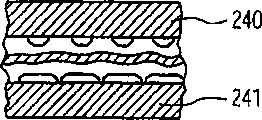
But Fig. 2 C shows a kind of arrangement, and wherein insulator and spiral are arranged in the base material 240,241.
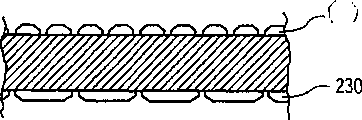
Fig. 3 is the cross sectional representation of the spiral around a kind of IOET of being wound on.
Fig. 4 shows the approximate equivalent circuit of the coiled arrangement shown in Figure 1A.
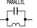
Fig. 5 shows the approximate equivalent circuit of the coiled arrangement shown in Figure 1B.
Fig. 6 and 7 shows the illustrative configurations of spiral, and this spiral is designed such that the present invention is as series resonator and parallel resonator.
Fig. 8 A and 8B represent the schematic diagram of cascaded structure respectively, the graph of a relation of impedance and frequency.
Typical impedance curve is drawn around first resonance frequency, and L and C represent it mainly is perceptual behavior or capacitive behavior respectively.
Fig. 8 C, 8D and 8E represent the schematic diagram of parallel-connection structure, the graph of a relation of impedance and frequency, and the electric capacity sketch that is used for the energy storage between two helical coils.
Fig. 8 F shows different configurations in two with 8G, and wherein by electric coupling, energy can enter and withdraw from this structure.
Fig. 9 A shows cross section according to planar resonator of the present invention, the top view of two coils, and depression of order equivalent electric circuit respectively to 9C.
Figure 10 shows equivalent top and bottom parallel resonator circuit, has illustrated how IOET works on this resonator, transmits electric energy with the form of mixed electric energy and magnetic energy.
Figure 11 is the schematic equivalent circuit according to a kind of series resonance battery charger of the present invention.
Figure 12 is the schematic diagram according to the feedback transformer that should invent immediately
Embodiment
Below describe and only be explanation, not conduct restriction.Also have many different structures also in the scope of aim of the present invention and claims.
Figure 1A-1B shows the variation of the integrated resonator of risking one's life according to an aspect of the present invention.Integrated resonator is to obtain by storage of electrical energy in the part of structure (geometry) time energy function, also stored magnetic energy in the part of same function.
Figure 1A shows the example of basic spiral 100, and Figure 1B shows bifilar helix 200.Certainly, those of ordinary skill in the art is to be understood that and the invention is not restricted to spiral and bifilar helix, can use the screw winding (multi-thread) of any amount as required.As shown in Figure 2, plane 200 has the spiral 210 of reeling on the end face of energy transfer interface (IOET) 215, and another spiral (not shown) of reeling on the bottom surface 220 of energy transfer interface (IOET).The axle of the spiral on the end face of IOET, the spiral on internal diameter and external diameter and the IOET bottom surface is similar to corresponding.
Fig. 2 B shows the cross section of the spiral 210 shown in Fig. 2 A.From this cross section as can be seen this spiral have the conductor 225,230 that is separated by IOET.The IOET layer that setting has between the spiral of magnetic coupling coefficient (promptly share with common flux) allows this integrated resonator storage of electrical energy, and this is the part of the structure time energy function of stored magnetic energy.
Should be noted that this IOET is unnecessary to be substrate when Fig. 2 B illustrates the IOET with spiral conductor of arranging up and down, shown in Fig. 2 C, IOET is arranged between substrate 240 and 241.These two base materials are any one sides of interface 235, if 235 be the air gap, then they are along this interface 235 separately.
This IOET can have μ
r>1, perhaps E
r>1, μ wherein
rBe the relative permeability of this material, E
rIt is the relative dielectric constant of this material.
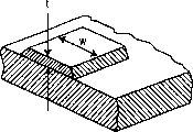
Fig. 3 shows the embodiment that can use a plurality of spirals in parallel or multi-thread spiral.As shown in Figure 3A, " w " equals width and " t " equals thickness.The spiral number of turns and size thereof, and connection and direction of rotation can be designed to obtain series connection, parallel connection, perhaps series connection/combination circuit in parallel.
Fig. 4,5,6 and 7 show coiled arrangement and equivalent electric circuit thereof, wherein use symbol such as A and B to distinguish each spiral.For example, Fig. 4 is the approximate equivalent circuit of Figure 1A, can further be simplified to equal set total capacitance and equal set total inductance as this circuit of first approximation.
For example should be noted that more complicated equivalent-circuit model can comprise transformer, by regarding it as transmission circuit network, the complexity of this model can expand to and comprise high order effects.
About Fig. 6 and 7, this figure shows series resonator and parallel resonator respectively.Should be noted that application possible in Fig. 6 is low pass filter and shunt load resonance oscillation semi-bridge.
About Fig. 8 A and 8B, around first resonance frequency, drawn typical impedance curve, and L and C represent to be mainly perception or capacitive behavior respectively.
The work of the series plane resonator in this part of the present invention is as follows: the self-resonant frequency that is lower than this structure when operating frequency fully, then between every suit spiral, there are a large amount of electric capacity, from the viewpoint of electric energy, this series resonator can be considered to the one port network of behavior such as capacitor.
Shown in Fig. 8 B, resonance frequency w place impedance minimum.At the higher frequency place, electric capacity is distributed on the spiral winding with inductance characteristic and between the spiral winding, thus as behavior more as the two-port network of transmission line.Simple equivalent lumped circuit model comprises the equivalent inductance of connecting with equivalent capacity.More load more precise analytic model also comprise transformer, by being seen as transmission circuit network, the complexity of this model can expand to and comprise high order effects.
About 8C and 8D, show a kind of simple equivalent circuit of parallel resonator.When operating frequency was lower than resonance frequency fully, the behavior of parallel resonator perception can be regarded the two-port network as.When operating frequency is higher than resonance frequency, from the electric energy viewpoint, the one port network of behavior such as capacitor when this parallel resonator can be found out.Resonance frequency place impedance maximum.
In addition, as shown in Fig. 8 F and 8G, provide two kinds of distinct methods that the passage of received energy with the output energy is provided.
Fig. 9 A has illustrated that IOET 903 scores of the present invention are wideer every the demarcation strip embodiment of two coils.As shown in the example among Fig. 9 A and the 9B, IOET is two spaces between the spiral.In this example, energy enters a coil from insulator 905, and transmits by this coil, as the air windings transformer.As shown in Fig. 9 B, have electric capacity between the coil, can be used as energy delivery.Fig. 9 C illustrates the equivalent electric circuit of the A1 shown in Fig. 9 B to the passage of A4.IOET is as the importance in the space between the coil, for example, can carry out wireless connections, as wireless battery charger.In a special example, do not use physical wire line to connect power supply and coil transmits energy to battery, battery that just can charging device (as mobile phone).Wireless connections allow to select this characteristic, suppose the energy frequency and the coil of transmission, make for example to exist capacitive to connect between battery and charger.
Figure 10 shows the equivalent electric circuit of top and bottom parallel resonator.Be to be understood that IOET1003 is not the set of discrete capacitor, but the electric capacity on the IOET between top and the bottom resonators.Under sufficiently high frequency, the ability transmission will be with the form of the electric energy on this resonator.So just obtain capacitive and connect, thereby allow electrical energy transfer.
Figure 11 is the schematic equivalent circuit according to series resonance battery charger of the present invention.This special battery charger has level translator, but can use the charger that does not have level translator.
In this circuit, can use different spiral transformer.Each spiral transformer can be modeled into the transformer with self leakage inductance Ls and magnetizing inductance Lm, like this, for given load specification, can calculate or simulate suitable resonant capacitance (Cr).In measurement, for used spiral transformer, this resonant capacitance of manual adjustment.This demarcation strip can be repacked into the flyback topology (shown in Figure 12) with floating holder, and when the node between C3 and C5 provided input DC, resonant capacitor C2 and rectifier diode were by short circuit, and D2 and D4 are removed.
Figure 12 is the schematic diagram according to the kickback transformer of instant invention.Whether carry out a test has a look and can use flyback topology to replace the series resonance topology.Use flyback topology that a plurality of advantages are arranged:
Need a Schottky diode to replace used 4 of series resonance charger among Figure 10.
The loss of rectifier diode less (significantly).
The operating frequency of duty ratio control is fixed.
Do not need resonant capacitor.
There is not after the resonant capacitor easier acquisition charger versatility.
In the example shown in Figure 11 and 12, should be appreciated that in the scope of aim of the present invention and claims, can carry out various variations.
The design parameter of planar resonator includes, but not limited to physical size, comprises aspect ratio, relative length, conductor thickness, material behavior is as dielectric constant (or permittivity), permeability comprises the loss factor of the material of the media that comprises IOET, the number of turns of spiral.
In addition, planar resonator can comprise the device that is used for connecting the device of battery charger or is equipped with the connection battery charger.
Can carry out various modifications to the present invention, these modifications all drop in the scope of aim of the present invention and claims.For example, the number of plies of this resonator, the IOET surface type, the quantity of spiral and thickness, the annex of illustrative examples such as battery, or the like, all can from this specification and in the structure described in the accompanying drawing, revise.Coil configuration can occupy more than a plane, especially when Resonator device is woven into fabric.
Claims (36)
1. planar power resonator comprises:
Energy transfer interface IOET (215), described IOET has end face and bottom surface;
Be arranged on first coil-conductor (210,225) on the described IOET end face;
Be arranged on second coil-conductor (230) on the described IOET bottom surface, described second coil-conductor has the vertical axis that aligns with described first coil-conductor; With
The described IOET and first coil-conductor have predetermined self-resonant frequency;
Wherein first and second conductors allow energy on this IOET, to transmit and
Wherein this coil-conductor comprises in series resonance structure and the parallel resonance structure one.
2. according to the planar power resonator of claim 1, wherein this first and second coil-conductor comprises the first and second pcb screw winding conductors (910 respectively, 920), and wherein this first and second spirality conductor and IOET (215) are integrated in the planar structure.
3. according to the planar power resonator of claim 1, wherein this IOET (215) comprises the non-conductive insulation film on this first coil-conductor bottom surface, non-conductive insulation film on the second coil-conductor end face, and emulsifying agent, separate by the air gap between this emulsifying agent and this first coil-conductor bottom surface.
4. according to the planar power resonator of claim 2, further comprise with this first and second screw windings conductor in the battery charger (1100,1200) of a coupling.
5. according to the planar power resonator of claim 4, another coupling in wherein load (1105,1205) and this first and second screw windings conductor.
6. according to the planar power resonator of claim 5, wherein this load is a magnetic couplings, and wherein energy by magnetic flux from this battery charger to this load transfer.
7. according to the planar power resonator of claim 1, wherein by the magnetic flux coupling of last first and second spirality conductors of this IOET (215), the signal that is applied to first coil-conductor (210,225) is passed on second coil-conductor (230).
8. according to the planar power resonator of claim 2, further comprise triple helical coiling conductor, on the IOET end face, this triple helical coiling conductor is designed to bi-filar spiral configuration (200) with the first screw winding conductor.
9. according to the planar power resonator of claim 2, further comprise the 4th screw winding conductor, on the IOET bottom surface, the 4th screw winding conductor is designed to bi-filar spiral configuration (200) with the second screw winding conductor.
10. according to the planar power resonator of claim 7, further comprise triple helical coiling conductor, on the IOET end face, this triple helical coiling conductor is designed to bi-filar spiral configuration (200) with the first screw winding conductor.
11. according to the planar power resonator of claim 10, wherein the bi-filar spiral configuration (200) on this IOET (215) end face and the bottom surface forms parallel resonator.
12. according to the planar power resonator of claim 10, wherein the bi-filar spiral configuration on this IOET end face and the bottom surface forms series resonator.
13. according to the planar power resonator of claim 7, wherein this first and spiral-shaped conductor arranged and this IOET parallel coupled.
14. according to the planar power resonator of claim 10, wherein this first and spiral-shaped conductor arranged and this IOET series coupled.
15. according to the planar power resonator of claim 10, wherein this second and the 4th spirality conductor and this IOET parallel coupled.
16. according to the planar power resonator of claim 10, wherein this second and the 4th spirality conductor and this IOET series coupled.
17., further comprise on this IOET end face more than second coil-conductor of arranging with cascaded structure on more than first coil-conductor arranging with cascaded structure and this IOET bottom surface according to the planar power resonator of claim 1.
18. according to the planar power resonator of claim 17, wherein these more than first and more than second coil-conductor are designed to parallel resonator.
19. according to the planar power resonator of claim 17, wherein these more than first and more than second coil-conductor are designed to series resonator.
20. according to the planar power resonator of claim 1, wherein said IOET comprises the relative permeability μ of this material
r, μ wherein
r>1.
21. according to the planar power resonator of claim 1, wherein said IOET comprises the relative dielectric constant E of this material
r, E wherein
r>1.
22. a planar power resonator comprises:
Be arranged on the planar spiral conductor 100 on the insulating material;
Be arranged on first couple input 207 on this spiral conductor first surface;
Be arranged on second couple input on the opposite one side with this planar spiral conductor device on this insulator.
23. a planar power resonator comprises a pair of planar coil conductor that has the air gap each other,
This is to first coil-conductor 910 of coil-conductor, and this first coil-conductor 910 contacts with insulator, and described first coil-conductor comprises the device that is used for the power supply coupling;
This is to second coil-conductor 920 of coil-conductor, and this second coil-conductor and the first coil-conductor vertical alignment, described second coil-conductor comprise the device that is used for the load coupling;
Wherein this allows energy to be delivered to second coil-conductor from this first coil-conductor to the electric capacity between the coil-conductor.
24., wherein be used for being coupled, and be used for charging, so that the wireless battery charging with the device and the battery 1105 of load coupling with the device and the battery charger 1100 of power supply coupling according to the planar power resonator of claim 23.
25. a planar power resonator comprises:
Energy transfer interface (IOET) 215, described IOET has end face and bottom surface;
Be arranged on first spirality conductor 210 on the described IOET end face;
Be arranged on second spirality conductor 230 on the described IOET bottom surface, described second spirality conductor has the vertical axis that aligns with described first spirality conductor;
Be arranged on first base material 240 on this IOET end face;
Be arranged on second base material 241 on this IOET bottom surface;
Wherein said IOET and this first and second spirality conductor have predetermined self-resonant frequency.
26. according to the planar power resonator of claim 25, further comprise with this first and second spirality conductor in the battery charger 1100,1200 of a coupling.
27. according to the planar power resonator of claim 25, wherein said IOET comprises the relative permeability μ of this material
r, μ wherein
r>1.
28. according to the planar power resonator of claim 25, wherein said IOET comprises the relative dielectric constant E of this material
r, E wherein
r>1.
29. a method that is provided for the planar power resonator of noncontact power transmission comprises step:
(a) provide energy transfer interface (IOET), described IOET has end face and bottom surface;
(b) first spirality conductor is arranged on the end face of described IOET;
(c) second spirality conductor is arranged on the bottom surface of described IOET, makes described second spirality conductor have the vertical axis that aligns with described first spirality conductor;
Wherein said IOET and described first and second spirality conductors are selected to have predetermined self-resonant frequency; With
Wherein said first and second spirals are aligned to one of series resonator and parallel resonance apparatus.
30. method according to claim 29, wherein step (b) further is included on the IOET end face spiral-shaped conductor arranged is designed to bi-filar spiral configuration with first spirality conductor, and step (c) further is included on the IOET bottom surface the 4th spirality conductor is designed to bi-filar spiral configuration with second spirality conductor.
31. method according to claim 29, wherein step (b) further is included on the IOET end face more than first spirality conductor is designed to multi-thread helical structure with first spirality conductor, and step (c) further is included on the IOET bottom surface more than second spirality conductor is designed to multi-thread helical structure with second spirality conductor.
32. according to the method for claim 31, wherein these more than first and more than second spirality conductor are designed to parallel resonator.
33. according to the method for claim 31, wherein these more than first and more than second spirality conductor are designed to series resonator.
34. according to the method for claim 33, wherein the described IOET that provides in the step (a) comprises the relative permeability μ of this material
r, μ wherein
r>1.
35. according to the method for claim 33, wherein said IOET comprises relative dielectric constant E
r, E wherein
r>1.
36. a method that is used to provide the planar power resonator comprises step:
(a) planar spiral conductor is arranged on the insulating material;
(b) first surface of connection first couple input and this spiral conductor;
(c) on the opposite one side with this planar spiral conductor second couple input is being set on this insulator.
Applications Claiming Priority (2)
| Application Number | Priority Date | Filing Date | Title |
|---|---|---|---|
| US10/180,403 | 2002-06-26 | ||
| US10/180,403 US6960968B2 (en) | 2002-06-26 | 2002-06-26 | Planar resonator for wireless power transfer |
Publications (1)
| Publication Number | Publication Date |
|---|---|
| CN1663118A true CN1663118A (en) | 2005-08-31 |
Family
ID=29778925
Family Applications (1)
| Application Number | Title | Priority Date | Filing Date |
|---|---|---|---|
| CN038148978A Pending CN1663118A (en) | 2002-06-26 | 2003-06-10 | Planar resonator for wireless power transfer |
Country Status (9)
| Country | Link |
|---|---|
| US (1) | US6960968B2 (en) |
| EP (1) | EP1520342B1 (en) |
| JP (1) | JP2005531242A (en) |
| KR (1) | KR20050013605A (en) |
| CN (1) | CN1663118A (en) |
| AT (1) | ATE426941T1 (en) |
| AU (1) | AU2003239738A1 (en) |
| DE (1) | DE60326849D1 (en) |
| WO (1) | WO2004004118A1 (en) |
Cited By (17)
| Publication number | Priority date | Publication date | Assignee | Title |
|---|---|---|---|---|
| CN101567585A (en) * | 2008-04-25 | 2009-10-28 | 精工爱普生株式会社 | Coil unit and electronic apparatus using the same |
| CN102171777A (en) * | 2008-10-02 | 2011-08-31 | 丰田自动车株式会社 | Self-resonant coil, contactless power transferring apparatus, and vehicle |
| CN102340185A (en) * | 2010-05-12 | 2012-02-01 | 通用电气公司 | Dielectric materials for power transfer system |
| CN102640394A (en) * | 2009-11-30 | 2012-08-15 | 三星电子株式会社 | Wireless power transceiver and wireless power system |
| CN102870338A (en) * | 2010-03-10 | 2013-01-09 | 无线电力公司 | Wireless energy transfer converters |
| CN103222146A (en) * | 2010-10-28 | 2013-07-24 | 皇家飞利浦电子股份有限公司 | Wireless electrical power supply unit and arrangement comprising a light transmissive cover and lighting system |
| CN101971458B (en) * | 2007-11-09 | 2013-08-07 | 香港城市大学 | Planar battery charging system |
| CN101720529B (en) * | 2007-03-02 | 2014-05-28 | 高通股份有限公司 | Wireless power apparatus and methods |
| CN101911029B (en) * | 2007-11-16 | 2014-08-06 | 高通股份有限公司 | Wireless power bridge |
| CN104885327A (en) * | 2012-10-19 | 2015-09-02 | 无线电力公司 | Foreign object detection in wireless energy transfer systems |
| US9444520B2 (en) | 2008-09-27 | 2016-09-13 | Witricity Corporation | Wireless energy transfer converters |
| CN106464024A (en) * | 2014-03-05 | 2017-02-22 | 威泰克有限公司 | Assembly for inductive energy transfer |
| US9748039B2 (en) | 2008-09-27 | 2017-08-29 | Witricity Corporation | Wireless energy transfer resonator thermal management |
| CN103944196B (en) * | 2008-03-13 | 2017-09-22 | 捷通国际有限公司 | Induction power supply system with multiple coil primaries |
| CN108352248A (en) * | 2015-06-29 | 2018-07-31 | 无线先进车辆电气化有限公司 | Winding is padded using the low inductance of the matching winding of multiple helicals |
| CN111355308A (en) * | 2018-12-24 | 2020-06-30 | 中国科学院半导体研究所 | Wireless energy supply flexible light-emitting system and preparation method of wireless energy receiving end device thereof |
| CN117458726A (en) * | 2023-10-13 | 2024-01-26 | 北京领创医谷科技发展有限责任公司 | Transmitting electrode for electric field coupling energy transfer |
Families Citing this family (462)
| Publication number | Priority date | Publication date | Assignee | Title |
|---|---|---|---|---|
| US8350655B2 (en) * | 2003-02-26 | 2013-01-08 | Analogic Corporation | Shielded power coupling device |
| US7868723B2 (en) * | 2003-02-26 | 2011-01-11 | Analogic Corporation | Power coupling device |
| US9368272B2 (en) | 2003-02-26 | 2016-06-14 | Analogic Corporation | Shielded power coupling device |
| US9490063B2 (en) | 2003-02-26 | 2016-11-08 | Analogic Corporation | Shielded power coupling device |
| WO2005106901A2 (en) | 2004-05-04 | 2005-11-10 | Philips Intellectual Property & Standards Gmbh | A wireless powering device, an energizable load, a wireless system and a method for a wireless energy transfer |
| US9044201B2 (en) * | 2004-07-12 | 2015-06-02 | St. Jude Medical Coordination Center Bvba | Wireless communication of physiological variables using spread spectrum |
| US20060009817A1 (en) * | 2004-07-12 | 2006-01-12 | Radi Medical Systems Ab | Wireless communication of physiological variables |
| DE102005024450B3 (en) * | 2005-05-24 | 2006-05-18 | Dräger Safety AG & Co. KGaA | Modular system of electronic units worn close to the body automatically activates electronic components coupled to common bus system if minimum configuration of electronic components is coupled to bus system |
| CA2511051A1 (en) * | 2005-06-28 | 2006-12-29 | Roger J. Soar | Contactless battery charging apparel |
| US7825543B2 (en) * | 2005-07-12 | 2010-11-02 | Massachusetts Institute Of Technology | Wireless energy transfer |
| AU2006269374C1 (en) * | 2005-07-12 | 2010-03-25 | Massachusetts Institute Of Technology | Wireless non-radiative energy transfer |
| GB0517082D0 (en) * | 2005-08-19 | 2005-09-28 | Univ City Hong Kong | Auxiliary winding for improved performance of a planar inductive charging platform |
| CN1921301B (en) * | 2005-08-26 | 2010-09-29 | 鸿富锦精密工业(深圳)有限公司 | Surface acoustic wave element |
| US7566984B2 (en) * | 2005-09-13 | 2009-07-28 | Nissan Technical Center North America, Inc. | Vehicle cabin power transfer arrangement |
| JP4813171B2 (en) * | 2005-12-16 | 2011-11-09 | 株式会社豊田自動織機 | Stator manufacturing method and manufacturing apparatus |
| US8447234B2 (en) | 2006-01-18 | 2013-05-21 | Qualcomm Incorporated | Method and system for powering an electronic device via a wireless link |
| US9130602B2 (en) | 2006-01-18 | 2015-09-08 | Qualcomm Incorporated | Method and apparatus for delivering energy to an electrical or electronic device via a wireless link |
| JP4855150B2 (en) * | 2006-06-09 | 2012-01-18 | 株式会社トプコン | Fundus observation apparatus, ophthalmic image processing apparatus, and ophthalmic image processing program |
| US7411363B2 (en) * | 2006-06-26 | 2008-08-12 | Lam Dat D | Conservation of electrical energy and electro-magnetic power in motor, generator, and product components |
| US7548489B1 (en) | 2006-07-05 | 2009-06-16 | The United States Of America As Represented By The Secretary Of The Navy | Method for designing a resonant acoustic projector |
| US7443764B1 (en) | 2006-07-05 | 2008-10-28 | The United States Of America As Represented By The Secretary Of The Navy | Resonant acoustic projector |
| US7909483B2 (en) | 2006-07-21 | 2011-03-22 | Koninklijke Philips Electronics N.V. | Lighting system |
| KR100921383B1 (en) * | 2006-09-08 | 2009-10-14 | 가부시키가이샤 엔.티.티.도코모 | Variable resonator, variable bandwidth filter, and electric circuit device |
| WO2008050292A2 (en) * | 2006-10-26 | 2008-05-02 | Koninklijke Philips Electronics N.V. | Floor covering and inductive power system |
| KR100859320B1 (en) * | 2007-02-06 | 2008-09-19 | 한국과학기술원 | Contactless communication apparatus among clothes |
| US8378523B2 (en) | 2007-03-02 | 2013-02-19 | Qualcomm Incorporated | Transmitters and receivers for wireless energy transfer |
| US8378522B2 (en) | 2007-03-02 | 2013-02-19 | Qualcomm, Incorporated | Maximizing power yield from wireless power magnetic resonators |
| US9421388B2 (en) | 2007-06-01 | 2016-08-23 | Witricity Corporation | Power generation for implantable devices |
| US8805530B2 (en) | 2007-06-01 | 2014-08-12 | Witricity Corporation | Power generation for implantable devices |
| US9124120B2 (en) | 2007-06-11 | 2015-09-01 | Qualcomm Incorporated | Wireless power system and proximity effects |
| JP4420073B2 (en) * | 2007-07-11 | 2010-02-24 | セイコーエプソン株式会社 | Coil unit and electronic equipment |
| EP2176939B1 (en) | 2007-08-09 | 2017-09-13 | Qualcomm Incorporated | Increasing the q factor of a resonator |
| WO2009033043A2 (en) * | 2007-09-05 | 2009-03-12 | University Of Florida Research Foundation, Inc. | Planar near-field wireless power charger and high-speed data communication platform |
| KR101312215B1 (en) | 2007-10-11 | 2013-09-27 | 퀄컴 인코포레이티드 | Wireless power transfer using magneto mechanical systems |
| US7962186B2 (en) * | 2007-10-24 | 2011-06-14 | Nokia Corporation | Method and apparatus for transferring electrical power in an electronic device |
| US7998089B2 (en) * | 2007-11-08 | 2011-08-16 | Radi Medical Systems Ab | Method of making a guide wire based assembly and reusing an energy source |
| US8974398B2 (en) * | 2007-11-08 | 2015-03-10 | St. Jude Medical Coordination Center Bvba | Removable energy source for sensor guidewire |
| KR101371765B1 (en) * | 2007-11-15 | 2014-03-11 | 포항공과대학교 산학협력단 | Apparatus and system for transfering power wirelessly |
| US7843288B2 (en) * | 2007-11-15 | 2010-11-30 | Samsung Electronics Co., Ltd. | Apparatus and system for transmitting power wirelessly |
| RU2517435C2 (en) | 2007-12-21 | 2014-05-27 | Эксесс Бизнесс Груп Интернешнл Ллс | Scheme for inductive power transmission |
| US8791600B2 (en) * | 2007-12-21 | 2014-07-29 | Roger J. Soar | Vehicle seat inductive charger and data transmitter |
| US9126514B2 (en) | 2007-12-21 | 2015-09-08 | Cynetic Designs Ltd | Vehicle seat inductive charger and data transmitter |
| US9472971B2 (en) | 2007-12-21 | 2016-10-18 | Cynetic Designs Ltd. | Wireless inductive charging of weapon system energy source |
| US9293927B2 (en) | 2007-12-21 | 2016-03-22 | Cynetic Designs Ltd. | Inductively coupled power and data transmission system |
| US8633616B2 (en) * | 2007-12-21 | 2014-01-21 | Cynetic Designs Ltd. | Modular pocket with inductive power and data |
| US7973296B2 (en) * | 2008-03-05 | 2011-07-05 | Tetraheed Llc | Electromagnetic systems with double-resonant spiral coil components |
| US8629576B2 (en) | 2008-03-28 | 2014-01-14 | Qualcomm Incorporated | Tuning and gain control in electro-magnetic power systems |
| DE102008017762A1 (en) * | 2008-04-08 | 2009-10-29 | Hydrotech International Ltd. | Magnetic coil for the generation of alternating magnetic fields with low reactive impedance in planar design, producible by application of layer technology as well as magnetic field source, current and voltage transformer, transformer or transformer |
| KR101589836B1 (en) | 2008-04-21 | 2016-01-28 | 퀄컴 인코포레이티드 | Short range efficient wireless power transfer |
| US20110036448A1 (en) * | 2008-04-29 | 2011-02-17 | Koninklijke Philips Electronics N.V. | Electronic textile |
| EP2281322B1 (en) * | 2008-05-14 | 2016-03-23 | Massachusetts Institute of Technology | Wireless energy transfer, including interference enhancement |
| ITRE20080077A1 (en) * | 2008-08-07 | 2010-02-08 | Andrea Spaggiari | CAPACITIVE SYSTEM OF TRANSFER OF ELECTRIC POWER |
| US8421274B2 (en) * | 2008-09-12 | 2013-04-16 | University Of Pittsburgh-Of The Commonwealth System Of Higher Education | Wireless energy transfer system |
| US8946938B2 (en) | 2008-09-27 | 2015-02-03 | Witricity Corporation | Safety systems for wireless energy transfer in vehicle applications |
| US8324759B2 (en) * | 2008-09-27 | 2012-12-04 | Witricity Corporation | Wireless energy transfer using magnetic materials to shape field and reduce loss |
| US8692410B2 (en) * | 2008-09-27 | 2014-04-08 | Witricity Corporation | Wireless energy transfer with frequency hopping |
| US8552592B2 (en) * | 2008-09-27 | 2013-10-08 | Witricity Corporation | Wireless energy transfer with feedback control for lighting applications |
| US9744858B2 (en) | 2008-09-27 | 2017-08-29 | Witricity Corporation | System for wireless energy distribution in a vehicle |
| US8304935B2 (en) * | 2008-09-27 | 2012-11-06 | Witricity Corporation | Wireless energy transfer using field shaping to reduce loss |
| US8928276B2 (en) | 2008-09-27 | 2015-01-06 | Witricity Corporation | Integrated repeaters for cell phone applications |
| US8482158B2 (en) * | 2008-09-27 | 2013-07-09 | Witricity Corporation | Wireless energy transfer using variable size resonators and system monitoring |
| US8569914B2 (en) | 2008-09-27 | 2013-10-29 | Witricity Corporation | Wireless energy transfer using object positioning for improved k |
| US9577436B2 (en) | 2008-09-27 | 2017-02-21 | Witricity Corporation | Wireless energy transfer for implantable devices |
| US8907531B2 (en) | 2008-09-27 | 2014-12-09 | Witricity Corporation | Wireless energy transfer with variable size resonators for medical applications |
| US8669676B2 (en) | 2008-09-27 | 2014-03-11 | Witricity Corporation | Wireless energy transfer across variable distances using field shaping with magnetic materials to improve the coupling factor |
| US20100277121A1 (en) * | 2008-09-27 | 2010-11-04 | Hall Katherine L | Wireless energy transfer between a source and a vehicle |
| US9093853B2 (en) | 2008-09-27 | 2015-07-28 | Witricity Corporation | Flexible resonator attachment |
| US8772973B2 (en) * | 2008-09-27 | 2014-07-08 | Witricity Corporation | Integrated resonator-shield structures |
| US8466583B2 (en) | 2008-09-27 | 2013-06-18 | Witricity Corporation | Tunable wireless energy transfer for outdoor lighting applications |
| US8643326B2 (en) * | 2008-09-27 | 2014-02-04 | Witricity Corporation | Tunable wireless energy transfer systems |
| US9601261B2 (en) | 2008-09-27 | 2017-03-21 | Witricity Corporation | Wireless energy transfer using repeater resonators |
| JP2012504387A (en) * | 2008-09-27 | 2012-02-16 | ウィトリシティ コーポレーション | Wireless energy transfer system |
| US8598743B2 (en) | 2008-09-27 | 2013-12-03 | Witricity Corporation | Resonator arrays for wireless energy transfer |
| US8400017B2 (en) | 2008-09-27 | 2013-03-19 | Witricity Corporation | Wireless energy transfer for computer peripheral applications |
| US8912687B2 (en) | 2008-09-27 | 2014-12-16 | Witricity Corporation | Secure wireless energy transfer for vehicle applications |
| US8901779B2 (en) | 2008-09-27 | 2014-12-02 | Witricity Corporation | Wireless energy transfer with resonator arrays for medical applications |
| US20110043049A1 (en) * | 2008-09-27 | 2011-02-24 | Aristeidis Karalis | Wireless energy transfer with high-q resonators using field shaping to improve k |
| US8476788B2 (en) | 2008-09-27 | 2013-07-02 | Witricity Corporation | Wireless energy transfer with high-Q resonators using field shaping to improve K |
| US9065423B2 (en) | 2008-09-27 | 2015-06-23 | Witricity Corporation | Wireless energy distribution system |
| US8686598B2 (en) | 2008-09-27 | 2014-04-01 | Witricity Corporation | Wireless energy transfer for supplying power and heat to a device |
| US9318922B2 (en) | 2008-09-27 | 2016-04-19 | Witricity Corporation | Mechanically removable wireless power vehicle seat assembly |
| US20120091949A1 (en) * | 2008-09-27 | 2012-04-19 | Campanella Andrew J | Wireless energy transfer for energizing power tools |
| US8629578B2 (en) | 2008-09-27 | 2014-01-14 | Witricity Corporation | Wireless energy transfer systems |
| US9035499B2 (en) | 2008-09-27 | 2015-05-19 | Witricity Corporation | Wireless energy transfer for photovoltaic panels |
| US8957549B2 (en) | 2008-09-27 | 2015-02-17 | Witricity Corporation | Tunable wireless energy transfer for in-vehicle applications |
| US8922066B2 (en) | 2008-09-27 | 2014-12-30 | Witricity Corporation | Wireless energy transfer with multi resonator arrays for vehicle applications |
| US9160203B2 (en) | 2008-09-27 | 2015-10-13 | Witricity Corporation | Wireless powered television |
| US9105959B2 (en) | 2008-09-27 | 2015-08-11 | Witricity Corporation | Resonator enclosure |
| US9184595B2 (en) | 2008-09-27 | 2015-11-10 | Witricity Corporation | Wireless energy transfer in lossy environments |
| US8471410B2 (en) | 2008-09-27 | 2013-06-25 | Witricity Corporation | Wireless energy transfer over distance using field shaping to improve the coupling factor |
| US8461721B2 (en) | 2008-09-27 | 2013-06-11 | Witricity Corporation | Wireless energy transfer using object positioning for low loss |
| US8723366B2 (en) * | 2008-09-27 | 2014-05-13 | Witricity Corporation | Wireless energy transfer resonator enclosures |
| US8587155B2 (en) * | 2008-09-27 | 2013-11-19 | Witricity Corporation | Wireless energy transfer using repeater resonators |
| US8461722B2 (en) | 2008-09-27 | 2013-06-11 | Witricity Corporation | Wireless energy transfer using conducting surfaces to shape field and improve K |
| US9601266B2 (en) | 2008-09-27 | 2017-03-21 | Witricity Corporation | Multiple connected resonators with a single electronic circuit |
| US8933594B2 (en) | 2008-09-27 | 2015-01-13 | Witricity Corporation | Wireless energy transfer for vehicles |
| US8901778B2 (en) | 2008-09-27 | 2014-12-02 | Witricity Corporation | Wireless energy transfer with variable size resonators for implanted medical devices |
| US9601270B2 (en) | 2008-09-27 | 2017-03-21 | Witricity Corporation | Low AC resistance conductor designs |
| US8587153B2 (en) | 2008-09-27 | 2013-11-19 | Witricity Corporation | Wireless energy transfer using high Q resonators for lighting applications |
| US9544683B2 (en) | 2008-09-27 | 2017-01-10 | Witricity Corporation | Wirelessly powered audio devices |
| US9106203B2 (en) | 2008-09-27 | 2015-08-11 | Witricity Corporation | Secure wireless energy transfer in medical applications |
| US8461720B2 (en) * | 2008-09-27 | 2013-06-11 | Witricity Corporation | Wireless energy transfer using conducting surfaces to shape fields and reduce loss |
| US20110074346A1 (en) * | 2009-09-25 | 2011-03-31 | Hall Katherine L | Vehicle charger safety system and method |
| US8410636B2 (en) | 2008-09-27 | 2013-04-02 | Witricity Corporation | Low AC resistance conductor designs |
| US8487480B1 (en) | 2008-09-27 | 2013-07-16 | Witricity Corporation | Wireless energy transfer resonator kit |
| US9515494B2 (en) | 2008-09-27 | 2016-12-06 | Witricity Corporation | Wireless power system including impedance matching network |
| US8937408B2 (en) | 2008-09-27 | 2015-01-20 | Witricity Corporation | Wireless energy transfer for medical applications |
| US9246336B2 (en) | 2008-09-27 | 2016-01-26 | Witricity Corporation | Resonator optimizations for wireless energy transfer |
| US9396867B2 (en) | 2008-09-27 | 2016-07-19 | Witricity Corporation | Integrated resonator-shield structures |
| US8441154B2 (en) | 2008-09-27 | 2013-05-14 | Witricity Corporation | Multi-resonator wireless energy transfer for exterior lighting |
| US8963488B2 (en) | 2008-09-27 | 2015-02-24 | Witricity Corporation | Position insensitive wireless charging |
| US8692412B2 (en) * | 2008-09-27 | 2014-04-08 | Witricity Corporation | Temperature compensation in a wireless transfer system |
| EP2345100B1 (en) | 2008-10-01 | 2018-12-05 | Massachusetts Institute of Technology | Efficient near-field wireless energy transfer using adiabatic system variations |
| UY32240A (en) | 2008-11-14 | 2010-06-30 | Boeringer Ingelheim Kg | NEW 2,4-DIAMINOPIRIMIDINAS, ITS PHARMACEUTICALLY ACCEPTABLE SALTS, COMPOSITIONS CONTAINING THEM AND APPLICATIONS. |
| KR101455825B1 (en) * | 2008-12-18 | 2014-10-30 | 삼성전자 주식회사 | Resonator for wireless power transmission |
| US9132250B2 (en) * | 2009-09-03 | 2015-09-15 | Breathe Technologies, Inc. | Methods, systems and devices for non-invasive ventilation including a non-sealing ventilation interface with an entrainment port and/or pressure feature |
| CA2752573A1 (en) * | 2009-02-13 | 2010-08-19 | Witricity Corporation | Wireless energy transfer in lossy environments |
| CN104393687B (en) | 2009-02-26 | 2017-08-11 | 英属哥伦比亚大学 | Receiver and power transmitting device |
| US9208942B2 (en) | 2009-03-09 | 2015-12-08 | Nucurrent, Inc. | Multi-layer-multi-turn structure for high efficiency wireless communication |
| US11476566B2 (en) * | 2009-03-09 | 2022-10-18 | Nucurrent, Inc. | Multi-layer-multi-turn structure for high efficiency wireless communication |
| WO2010104569A1 (en) | 2009-03-09 | 2010-09-16 | Neurds Inc. | System and method for wireless power transfer in implantable medical devices |
| US9439287B2 (en) | 2009-03-09 | 2016-09-06 | Nucurrent, Inc. | Multi-layer wire structure for high efficiency wireless communication |
| US9232893B2 (en) | 2009-03-09 | 2016-01-12 | Nucurrent, Inc. | Method of operation of a multi-layer-multi-turn structure for high efficiency wireless communication |
| US9306358B2 (en) | 2009-03-09 | 2016-04-05 | Nucurrent, Inc. | Method for manufacture of multi-layer wire structure for high efficiency wireless communication |
| US9300046B2 (en) | 2009-03-09 | 2016-03-29 | Nucurrent, Inc. | Method for manufacture of multi-layer-multi-turn high efficiency inductors |
| US9444213B2 (en) | 2009-03-09 | 2016-09-13 | Nucurrent, Inc. | Method for manufacture of multi-layer wire structure for high efficiency wireless communication |
| EP2427944B1 (en) | 2009-05-07 | 2018-07-11 | Telecom Italia S.p.A. | System for transferring energy wirelessly |
| WO2010131983A1 (en) * | 2009-05-12 | 2010-11-18 | Auckland Uniservices Limited | Inductive power transfer apparatus and electric autocycle charger including the inductive power transfer apparatus |
| WO2010136927A2 (en) * | 2009-05-25 | 2010-12-02 | Koninklijke Philips Electronics N.V. | Method and device for detecting a device in a wireless power transmission system |
| WO2011029074A1 (en) | 2009-09-03 | 2011-03-10 | Breathe Technologies, Inc. | Methods, systems and devices for non-invasive ventilation including a non-sealing ventilation interface with an entrainment port and/or pressure feature |
| US20150255994A1 (en) * | 2009-09-25 | 2015-09-10 | Witricity Corporation | Safety systems for wireless energy transfer in vehicle applications |
| KR101197579B1 (en) * | 2009-11-04 | 2012-11-06 | 한국전기연구원 | Space-adaptive Wireless Power Transmission System and Method using Resonance of Evanescent Waves |
| WO2011055905A2 (en) * | 2009-11-04 | 2011-05-12 | 한국전기연구원 | System and method for space-adaptive wireless power transmission using evanescent wave resonance |
| US20110133565A1 (en) * | 2009-12-03 | 2011-06-09 | Koon Hoo Teo | Wireless Energy Transfer with Negative Index Material |
| US20110133566A1 (en) * | 2009-12-03 | 2011-06-09 | Koon Hoo Teo | Wireless Energy Transfer with Negative Material |
| US20110133567A1 (en) * | 2009-12-03 | 2011-06-09 | Koon Hoo Teo | Wireless Energy Transfer with Negative Index Material |
| US9461505B2 (en) | 2009-12-03 | 2016-10-04 | Mitsubishi Electric Research Laboratories, Inc. | Wireless energy transfer with negative index material |
| KR101718312B1 (en) | 2009-12-14 | 2017-03-21 | 삼성전자주식회사 | Wireless Power Transmitter and Wireless Power Receiver |
| JP5016069B2 (en) * | 2010-01-12 | 2012-09-05 | トヨタ自動車株式会社 | Power transmission system and vehicle power supply device |
| US8674550B2 (en) | 2010-03-25 | 2014-03-18 | General Electric Company | Contactless power transfer system and method |
| JP2011211792A (en) * | 2010-03-29 | 2011-10-20 | Equos Research Co Ltd | Noncontact power supply system |
| US10343535B2 (en) | 2010-04-08 | 2019-07-09 | Witricity Corporation | Wireless power antenna alignment adjustment system for vehicles |
| US9561730B2 (en) | 2010-04-08 | 2017-02-07 | Qualcomm Incorporated | Wireless power transmission in electric vehicles |
| US9174876B2 (en) * | 2010-05-12 | 2015-11-03 | General Electric Company | Dielectric materials for power transfer system |
| US8968603B2 (en) | 2010-05-12 | 2015-03-03 | General Electric Company | Dielectric materials |
| US8198752B2 (en) | 2010-05-12 | 2012-06-12 | General Electric Company | Electrical coupling apparatus and method |
| JP5747446B2 (en) * | 2010-05-19 | 2015-07-15 | 株式会社オートネットワーク技術研究所 | Coil for wireless power transmission with power feeding unit and wireless power feeding system |
| US8441153B2 (en) | 2010-06-22 | 2013-05-14 | General Electric Company | Contactless power transfer system |
| US9552920B2 (en) | 2010-07-28 | 2017-01-24 | General Electric Company | Contactless power transfer system |
| EP2428969B1 (en) * | 2010-08-09 | 2016-10-19 | Parspour, Nejila | Coil arrangement for an inductive charging device |
| TWI449256B (en) | 2010-08-19 | 2014-08-11 | Ind Tech Res Inst | Electromagnetic transmission apparatus |
| KR101441453B1 (en) * | 2010-08-25 | 2014-09-18 | 한국전자통신연구원 | Apparatus and method for reducing electric field and radiation field in magnetic resonant coupling coils or magnetic induction device for wireless energy transfer |
| US9602168B2 (en) | 2010-08-31 | 2017-03-21 | Witricity Corporation | Communication in wireless energy transfer systems |
| US8174134B2 (en) * | 2010-10-28 | 2012-05-08 | General Electric Company | Systems for contactless power transfer |
| US9054745B2 (en) | 2010-12-22 | 2015-06-09 | Electronics And Telecommunications Research Institute | Apparatus for transmitting/receiving energy using a resonance structure in an energy system |
| FR2970367B1 (en) * | 2011-01-07 | 2013-01-11 | Renault Sa | METHOD FOR THERMALLY REGULATING AN ELEMENT OF A MOTOR VEHICLE AND SYSTEM FOR THERMALLY REGULATING THE SAME |
| US8849402B2 (en) | 2011-03-21 | 2014-09-30 | General Electric Company | System and method for contactless power transfer in implantable devices |
| US8552595B2 (en) | 2011-05-31 | 2013-10-08 | General Electric Company | System and method for contactless power transfer in portable image detectors |
| US9948145B2 (en) | 2011-07-08 | 2018-04-17 | Witricity Corporation | Wireless power transfer for a seat-vest-helmet system |
| EP2551988A3 (en) | 2011-07-28 | 2013-03-27 | General Electric Company | Dielectric materials for power transfer system |
| CN108110907B (en) | 2011-08-04 | 2022-08-02 | 韦特里西提公司 | Tunable wireless power supply architecture |
| ES2558182T3 (en) | 2011-09-09 | 2016-02-02 | Witricity Corporation | Detection of foreign objects in wireless energy transfer systems |
| US20130062966A1 (en) | 2011-09-12 | 2013-03-14 | Witricity Corporation | Reconfigurable control architectures and algorithms for electric vehicle wireless energy transfer systems |
| US20130068499A1 (en) * | 2011-09-15 | 2013-03-21 | Nucurrent Inc. | Method for Operation of Multi-Layer Wire Structure for High Efficiency Wireless Communication |
| US9318257B2 (en) | 2011-10-18 | 2016-04-19 | Witricity Corporation | Wireless energy transfer for packaging |
| KR20140085591A (en) | 2011-11-04 | 2014-07-07 | 위트리시티 코포레이션 | Wireless energy transfer modeling tool |
| US9079043B2 (en) | 2011-11-21 | 2015-07-14 | Thoratec Corporation | Transcutaneous power transmission utilizing non-planar resonators |
| US9306635B2 (en) | 2012-01-26 | 2016-04-05 | Witricity Corporation | Wireless energy transfer with reduced fields |
| US8933589B2 (en) | 2012-02-07 | 2015-01-13 | The Gillette Company | Wireless power transfer using separately tunable resonators |
| EP2660948A3 (en) | 2012-05-04 | 2015-06-24 | DET International Holding Limited | Multiple resonant cells for inductive charging pads |
| US9406435B2 (en) * | 2012-06-12 | 2016-08-02 | Georgia Tech Research Corporation | Misalignment insensitive wireless power transfer |
| US9343922B2 (en) | 2012-06-27 | 2016-05-17 | Witricity Corporation | Wireless energy transfer for rechargeable batteries |
| US9923386B1 (en) | 2012-07-06 | 2018-03-20 | Energous Corporation | Systems and methods for wireless power transmission by modifying a number of antenna elements used to transmit power waves to a receiver |
| US10141768B2 (en) | 2013-06-03 | 2018-11-27 | Energous Corporation | Systems and methods for maximizing wireless power transfer efficiency by instructing a user to change a receiver device's position |
| US10224982B1 (en) | 2013-07-11 | 2019-03-05 | Energous Corporation | Wireless power transmitters for transmitting wireless power and tracking whether wireless power receivers are within authorized locations |
| US9876380B1 (en) | 2013-09-13 | 2018-01-23 | Energous Corporation | Secured wireless power distribution system |
| US9876648B2 (en) | 2014-08-21 | 2018-01-23 | Energous Corporation | System and method to control a wireless power transmission system by configuration of wireless power transmission control parameters |
| US9867062B1 (en) | 2014-07-21 | 2018-01-09 | Energous Corporation | System and methods for using a remote server to authorize a receiving device that has requested wireless power and to determine whether another receiving device should request wireless power in a wireless power transmission system |
| US9831718B2 (en) | 2013-07-25 | 2017-11-28 | Energous Corporation | TV with integrated wireless power transmitter |
| US10270261B2 (en) | 2015-09-16 | 2019-04-23 | Energous Corporation | Systems and methods of object detection in wireless power charging systems |
| US9900057B2 (en) | 2012-07-06 | 2018-02-20 | Energous Corporation | Systems and methods for assigning groups of antenas of a wireless power transmitter to different wireless power receivers, and determining effective phases to use for wirelessly transmitting power using the assigned groups of antennas |
| US9825674B1 (en) | 2014-05-23 | 2017-11-21 | Energous Corporation | Enhanced transmitter that selects configurations of antenna elements for performing wireless power transmission and receiving functions |
| US10205239B1 (en) | 2014-05-07 | 2019-02-12 | Energous Corporation | Compact PIFA antenna |
| US9891669B2 (en) | 2014-08-21 | 2018-02-13 | Energous Corporation | Systems and methods for a configuration web service to provide configuration of a wireless power transmitter within a wireless power transmission system |
| US9966765B1 (en) | 2013-06-25 | 2018-05-08 | Energous Corporation | Multi-mode transmitter |
| US10124754B1 (en) | 2013-07-19 | 2018-11-13 | Energous Corporation | Wireless charging and powering of electronic sensors in a vehicle |
| US9124125B2 (en) | 2013-05-10 | 2015-09-01 | Energous Corporation | Wireless power transmission with selective range |
| US10063105B2 (en) | 2013-07-11 | 2018-08-28 | Energous Corporation | Proximity transmitters for wireless power charging systems |
| US9906065B2 (en) | 2012-07-06 | 2018-02-27 | Energous Corporation | Systems and methods of transmitting power transmission waves based on signals received at first and second subsets of a transmitter's antenna array |
| US10224758B2 (en) | 2013-05-10 | 2019-03-05 | Energous Corporation | Wireless powering of electronic devices with selective delivery range |
| US9438045B1 (en) | 2013-05-10 | 2016-09-06 | Energous Corporation | Methods and systems for maximum power point transfer in receivers |
| US9954374B1 (en) | 2014-05-23 | 2018-04-24 | Energous Corporation | System and method for self-system analysis for detecting a fault in a wireless power transmission Network |
| US10381880B2 (en) | 2014-07-21 | 2019-08-13 | Energous Corporation | Integrated antenna structure arrays for wireless power transmission |
| US10211674B1 (en) | 2013-06-12 | 2019-02-19 | Energous Corporation | Wireless charging using selected reflectors |
| US10992185B2 (en) | 2012-07-06 | 2021-04-27 | Energous Corporation | Systems and methods of using electromagnetic waves to wirelessly deliver power to game controllers |
| US10218227B2 (en) | 2014-05-07 | 2019-02-26 | Energous Corporation | Compact PIFA antenna |
| US10439448B2 (en) | 2014-08-21 | 2019-10-08 | Energous Corporation | Systems and methods for automatically testing the communication between wireless power transmitter and wireless power receiver |
| US9887739B2 (en) | 2012-07-06 | 2018-02-06 | Energous Corporation | Systems and methods for wireless power transmission by comparing voltage levels associated with power waves transmitted by antennas of a plurality of antennas of a transmitter to determine appropriate phase adjustments for the power waves |
| US10090886B1 (en) | 2014-07-14 | 2018-10-02 | Energous Corporation | System and method for enabling automatic charging schedules in a wireless power network to one or more devices |
| US10199835B2 (en) | 2015-12-29 | 2019-02-05 | Energous Corporation | Radar motion detection using stepped frequency in wireless power transmission system |
| US9887584B1 (en) | 2014-08-21 | 2018-02-06 | Energous Corporation | Systems and methods for a configuration web service to provide configuration of a wireless power transmitter within a wireless power transmission system |
| US10230266B1 (en) | 2014-02-06 | 2019-03-12 | Energous Corporation | Wireless power receivers that communicate status data indicating wireless power transmission effectiveness with a transmitter using a built-in communications component of a mobile device, and methods of use thereof |
| US9793758B2 (en) | 2014-05-23 | 2017-10-17 | Energous Corporation | Enhanced transmitter using frequency control for wireless power transmission |
| US10063064B1 (en) | 2014-05-23 | 2018-08-28 | Energous Corporation | System and method for generating a power receiver identifier in a wireless power network |
| US11502551B2 (en) | 2012-07-06 | 2022-11-15 | Energous Corporation | Wirelessly charging multiple wireless-power receivers using different subsets of an antenna array to focus energy at different locations |
| US9859756B2 (en) | 2012-07-06 | 2018-01-02 | Energous Corporation | Transmittersand methods for adjusting wireless power transmission based on information from receivers |
| US20150326070A1 (en) | 2014-05-07 | 2015-11-12 | Energous Corporation | Methods and Systems for Maximum Power Point Transfer in Receivers |
| US9368020B1 (en) | 2013-05-10 | 2016-06-14 | Energous Corporation | Off-premises alert system and method for wireless power receivers in a wireless power network |
| US10263432B1 (en) | 2013-06-25 | 2019-04-16 | Energous Corporation | Multi-mode transmitter with an antenna array for delivering wireless power and providing Wi-Fi access |
| US9893555B1 (en) | 2013-10-10 | 2018-02-13 | Energous Corporation | Wireless charging of tools using a toolbox transmitter |
| US9991741B1 (en) | 2014-07-14 | 2018-06-05 | Energous Corporation | System for tracking and reporting status and usage information in a wireless power management system |
| US9853692B1 (en) | 2014-05-23 | 2017-12-26 | Energous Corporation | Systems and methods for wireless power transmission |
| US9859797B1 (en) | 2014-05-07 | 2018-01-02 | Energous Corporation | Synchronous rectifier design for wireless power receiver |
| US9882427B2 (en) | 2013-05-10 | 2018-01-30 | Energous Corporation | Wireless power delivery using a base station to control operations of a plurality of wireless power transmitters |
| US9899873B2 (en) | 2014-05-23 | 2018-02-20 | Energous Corporation | System and method for generating a power receiver identifier in a wireless power network |
| US10211682B2 (en) | 2014-05-07 | 2019-02-19 | Energous Corporation | Systems and methods for controlling operation of a transmitter of a wireless power network based on user instructions received from an authenticated computing device powered or charged by a receiver of the wireless power network |
| US9838083B2 (en) | 2014-07-21 | 2017-12-05 | Energous Corporation | Systems and methods for communication with remote management systems |
| US10199849B1 (en) | 2014-08-21 | 2019-02-05 | Energous Corporation | Method for automatically testing the operational status of a wireless power receiver in a wireless power transmission system |
| US10243414B1 (en) | 2014-05-07 | 2019-03-26 | Energous Corporation | Wearable device with wireless power and payload receiver |
| US10075008B1 (en) | 2014-07-14 | 2018-09-11 | Energous Corporation | Systems and methods for manually adjusting when receiving electronic devices are scheduled to receive wirelessly delivered power from a wireless power transmitter in a wireless power network |
| US10965164B2 (en) | 2012-07-06 | 2021-03-30 | Energous Corporation | Systems and methods of wirelessly delivering power to a receiver device |
| US9871398B1 (en) | 2013-07-01 | 2018-01-16 | Energous Corporation | Hybrid charging method for wireless power transmission based on pocket-forming |
| US9876394B1 (en) | 2014-05-07 | 2018-01-23 | Energous Corporation | Boost-charger-boost system for enhanced power delivery |
| US20140008993A1 (en) | 2012-07-06 | 2014-01-09 | DvineWave Inc. | Methodology for pocket-forming |
| US9847677B1 (en) | 2013-10-10 | 2017-12-19 | Energous Corporation | Wireless charging and powering of healthcare gadgets and sensors |
| US10223717B1 (en) | 2014-05-23 | 2019-03-05 | Energous Corporation | Systems and methods for payment-based authorization of wireless power transmission service |
| US9143000B2 (en) | 2012-07-06 | 2015-09-22 | Energous Corporation | Portable wireless charging pad |
| US9941747B2 (en) | 2014-07-14 | 2018-04-10 | Energous Corporation | System and method for manually selecting and deselecting devices to charge in a wireless power network |
| US10211680B2 (en) | 2013-07-19 | 2019-02-19 | Energous Corporation | Method for 3 dimensional pocket-forming |
| US10128693B2 (en) | 2014-07-14 | 2018-11-13 | Energous Corporation | System and method for providing health safety in a wireless power transmission system |
| US10291066B1 (en) | 2014-05-07 | 2019-05-14 | Energous Corporation | Power transmission control systems and methods |
| US9948135B2 (en) | 2015-09-22 | 2018-04-17 | Energous Corporation | Systems and methods for identifying sensitive objects in a wireless charging transmission field |
| US10141791B2 (en) | 2014-05-07 | 2018-11-27 | Energous Corporation | Systems and methods for controlling communications during wireless transmission of power using application programming interfaces |
| US9843213B2 (en) | 2013-08-06 | 2017-12-12 | Energous Corporation | Social power sharing for mobile devices based on pocket-forming |
| US10206185B2 (en) | 2013-05-10 | 2019-02-12 | Energous Corporation | System and methods for wireless power transmission to an electronic device in accordance with user-defined restrictions |
| US10008889B2 (en) | 2014-08-21 | 2018-06-26 | Energous Corporation | Method for automatically testing the operational status of a wireless power receiver in a wireless power transmission system |
| US9876379B1 (en) | 2013-07-11 | 2018-01-23 | Energous Corporation | Wireless charging and powering of electronic devices in a vehicle |
| US9941707B1 (en) | 2013-07-19 | 2018-04-10 | Energous Corporation | Home base station for multiple room coverage with multiple transmitters |
| US10992187B2 (en) | 2012-07-06 | 2021-04-27 | Energous Corporation | System and methods of using electromagnetic waves to wirelessly deliver power to electronic devices |
| US9912199B2 (en) | 2012-07-06 | 2018-03-06 | Energous Corporation | Receivers for wireless power transmission |
| US10128699B2 (en) | 2014-07-14 | 2018-11-13 | Energous Corporation | Systems and methods of providing wireless power using receiver device sensor inputs |
| US10103582B2 (en) | 2012-07-06 | 2018-10-16 | Energous Corporation | Transmitters for wireless power transmission |
| US9450449B1 (en) | 2012-07-06 | 2016-09-20 | Energous Corporation | Antenna arrangement for pocket-forming |
| US9806564B2 (en) | 2014-05-07 | 2017-10-31 | Energous Corporation | Integrated rectifier and boost converter for wireless power transmission |
| US9853458B1 (en) | 2014-05-07 | 2017-12-26 | Energous Corporation | Systems and methods for device and power receiver pairing |
| US10186913B2 (en) | 2012-07-06 | 2019-01-22 | Energous Corporation | System and methods for pocket-forming based on constructive and destructive interferences to power one or more wireless power receivers using a wireless power transmitter including a plurality of antennas |
| US9939864B1 (en) | 2014-08-21 | 2018-04-10 | Energous Corporation | System and method to control a wireless power transmission system by configuration of wireless power transmission control parameters |
| US9859757B1 (en) | 2013-07-25 | 2018-01-02 | Energous Corporation | Antenna tile arrangements in electronic device enclosures |
| US9893768B2 (en) | 2012-07-06 | 2018-02-13 | Energous Corporation | Methodology for multiple pocket-forming |
| US9899861B1 (en) | 2013-10-10 | 2018-02-20 | Energous Corporation | Wireless charging methods and systems for game controllers, based on pocket-forming |
| US9941754B2 (en) | 2012-07-06 | 2018-04-10 | Energous Corporation | Wireless power transmission with selective range |
| US10291055B1 (en) | 2014-12-29 | 2019-05-14 | Energous Corporation | Systems and methods for controlling far-field wireless power transmission based on battery power levels of a receiving device |
| US10256657B2 (en) | 2015-12-24 | 2019-04-09 | Energous Corporation | Antenna having coaxial structure for near field wireless power charging |
| US9843201B1 (en) | 2012-07-06 | 2017-12-12 | Energous Corporation | Wireless power transmitter that selects antenna sets for transmitting wireless power to a receiver based on location of the receiver, and methods of use thereof |
| US10312715B2 (en) | 2015-09-16 | 2019-06-04 | Energous Corporation | Systems and methods for wireless power charging |
| US10090699B1 (en) | 2013-11-01 | 2018-10-02 | Energous Corporation | Wireless powered house |
| US9973021B2 (en) | 2012-07-06 | 2018-05-15 | Energous Corporation | Receivers for wireless power transmission |
| US9252628B2 (en) | 2013-05-10 | 2016-02-02 | Energous Corporation | Laptop computer as a transmitter for wireless charging |
| US9847679B2 (en) | 2014-05-07 | 2017-12-19 | Energous Corporation | System and method for controlling communication between wireless power transmitter managers |
| US10038337B1 (en) | 2013-09-16 | 2018-07-31 | Energous Corporation | Wireless power supply for rescue devices |
| US10193396B1 (en) | 2014-05-07 | 2019-01-29 | Energous Corporation | Cluster management of transmitters in a wireless power transmission system |
| US9893554B2 (en) | 2014-07-14 | 2018-02-13 | Energous Corporation | System and method for providing health safety in a wireless power transmission system |
| US9882430B1 (en) | 2014-05-07 | 2018-01-30 | Energous Corporation | Cluster management of transmitters in a wireless power transmission system |
| US10148097B1 (en) | 2013-11-08 | 2018-12-04 | Energous Corporation | Systems and methods for using a predetermined number of communication channels of a wireless power transmitter to communicate with different wireless power receivers |
| US10050462B1 (en) | 2013-08-06 | 2018-08-14 | Energous Corporation | Social power sharing for mobile devices based on pocket-forming |
| US10063106B2 (en) | 2014-05-23 | 2018-08-28 | Energous Corporation | System and method for a self-system analysis in a wireless power transmission network |
| US9787103B1 (en) | 2013-08-06 | 2017-10-10 | Energous Corporation | Systems and methods for wirelessly delivering power to electronic devices that are unable to communicate with a transmitter |
| US9824815B2 (en) | 2013-05-10 | 2017-11-21 | Energous Corporation | Wireless charging and powering of healthcare gadgets and sensors |
| US9812890B1 (en) | 2013-07-11 | 2017-11-07 | Energous Corporation | Portable wireless charging pad |
| WO2014018967A1 (en) | 2012-07-27 | 2014-01-30 | Thoratec Corporation | Self-tuning resonant power transfer systems |
| US9805863B2 (en) | 2012-07-27 | 2017-10-31 | Thoratec Corporation | Magnetic power transmission utilizing phased transmitter coil arrays and phased receiver coil arrays |
| US10525181B2 (en) | 2012-07-27 | 2020-01-07 | Tc1 Llc | Resonant power transfer system and method of estimating system state |
| US10251987B2 (en) | 2012-07-27 | 2019-04-09 | Tc1 Llc | Resonant power transmission coils and systems |
| WO2014018972A1 (en) | 2012-07-27 | 2014-01-30 | Thoratec Corporation | Computer modeling for resonant power transfer systems |
| EP4257174A3 (en) | 2012-07-27 | 2023-12-27 | Tc1 Llc | Thermal management for implantable wireless power transfer systems |
| US9825471B2 (en) | 2012-07-27 | 2017-11-21 | Thoratec Corporation | Resonant power transfer systems with protective algorithm |
| US10383990B2 (en) | 2012-07-27 | 2019-08-20 | Tc1 Llc | Variable capacitor for resonant power transfer systems |
| US9287607B2 (en) | 2012-07-31 | 2016-03-15 | Witricity Corporation | Resonator fine tuning |
| US9859744B2 (en) | 2012-08-03 | 2018-01-02 | Mediatek Singapore Pte. Ltd. | Dual-mode wireless power receiver |
| US10658869B2 (en) | 2012-08-03 | 2020-05-19 | Mediatek Inc. | Multi-mode, multi-standard wireless power transmitter coil assembly |
| US9912197B2 (en) | 2012-08-03 | 2018-03-06 | Mediatek Singapore Pte. Ltd. | Dual-mode wireless power receiver |
| US9697951B2 (en) | 2012-08-29 | 2017-07-04 | General Electric Company | Contactless power transfer system |
| US9595378B2 (en) | 2012-09-19 | 2017-03-14 | Witricity Corporation | Resonator enclosure |
| TW201417122A (en) * | 2012-10-22 | 2014-05-01 | Espower Electronics Inc | Coil for inductive coupled power transfer and electrical-field coupled power transfer |
| US9842684B2 (en) | 2012-11-16 | 2017-12-12 | Witricity Corporation | Systems and methods for wireless power system with improved performance and/or ease of use |
| DE102013226228A1 (en) * | 2012-12-21 | 2014-06-26 | Robert Bosch Gmbh | Induktivladespulenvorrichtung |
| KR102028057B1 (en) | 2013-01-22 | 2019-10-04 | 삼성전자주식회사 | Resonator with improved isolation |
| EP2984731B8 (en) | 2013-03-15 | 2019-06-26 | Tc1 Llc | Malleable tets coil with improved anatomical fit |
| US9680310B2 (en) | 2013-03-15 | 2017-06-13 | Thoratec Corporation | Integrated implantable TETS housing including fins and coil loops |
| EP2782262B1 (en) * | 2013-03-19 | 2015-05-06 | Tyco Electronics Nederland B.V. | Contactless coupler for capacitively coupled signal transmission |
| US9843763B2 (en) | 2013-05-10 | 2017-12-12 | Energous Corporation | TV system with wireless power transmitter |
| US9819230B2 (en) | 2014-05-07 | 2017-11-14 | Energous Corporation | Enhanced receiver for wireless power transmission |
| US9419443B2 (en) | 2013-05-10 | 2016-08-16 | Energous Corporation | Transducer sound arrangement for pocket-forming |
| US9537357B2 (en) | 2013-05-10 | 2017-01-03 | Energous Corporation | Wireless sound charging methods and systems for game controllers, based on pocket-forming |
| US9866279B2 (en) | 2013-05-10 | 2018-01-09 | Energous Corporation | Systems and methods for selecting which power transmitter should deliver wireless power to a receiving device in a wireless power delivery network |
| US9538382B2 (en) | 2013-05-10 | 2017-01-03 | Energous Corporation | System and method for smart registration of wireless power receivers in a wireless power network |
| US10103552B1 (en) | 2013-06-03 | 2018-10-16 | Energous Corporation | Protocols for authenticated wireless power transmission |
| US10003211B1 (en) | 2013-06-17 | 2018-06-19 | Energous Corporation | Battery life of portable electronic devices |
| US9521926B1 (en) | 2013-06-24 | 2016-12-20 | Energous Corporation | Wireless electrical temperature regulator for food and beverages |
| US9601267B2 (en) | 2013-07-03 | 2017-03-21 | Qualcomm Incorporated | Wireless power transmitter with a plurality of magnetic oscillators |
| US10021523B2 (en) | 2013-07-11 | 2018-07-10 | Energous Corporation | Proximity transmitters for wireless power charging systems |
| US9979440B1 (en) | 2013-07-25 | 2018-05-22 | Energous Corporation | Antenna tile arrangements configured to operate as one functional unit |
| US9857821B2 (en) | 2013-08-14 | 2018-01-02 | Witricity Corporation | Wireless power transfer frequency adjustment |
| US9729151B2 (en) | 2013-10-04 | 2017-08-08 | Intel Corporation | Isolation module for use between power rails in an integrated circuit |
| ES2535562B2 (en) | 2013-10-11 | 2016-05-25 | Univ Politècnica De València | WIRELESS POWER TRANSFER DEVICE |
| JP6521992B2 (en) | 2013-11-11 | 2019-05-29 | ティーシー1 エルエルシー | Resonance power transmission system having communication |
| EP3072210B1 (en) | 2013-11-11 | 2023-12-20 | Tc1 Llc | Resonant power transfer systems with communications |
| EP3069358B1 (en) | 2013-11-11 | 2019-06-12 | Tc1 Llc | Hinged resonant power transfer coil |
| US9780573B2 (en) | 2014-02-03 | 2017-10-03 | Witricity Corporation | Wirelessly charged battery system |
| US9935482B1 (en) | 2014-02-06 | 2018-04-03 | Energous Corporation | Wireless power transmitters that transmit at determined times based on power availability and consumption at a receiving mobile device |
| US10075017B2 (en) | 2014-02-06 | 2018-09-11 | Energous Corporation | External or internal wireless power receiver with spaced-apart antenna elements for charging or powering mobile devices using wirelessly delivered power |
| US9952266B2 (en) | 2014-02-14 | 2018-04-24 | Witricity Corporation | Object detection for wireless energy transfer systems |
| WO2015127127A1 (en) | 2014-02-23 | 2015-08-27 | Apple Inc. | Adjusting filter in a coupled coil system |
| KR20160117587A (en) | 2014-02-23 | 2016-10-10 | 애플 인크. | Impedance matching for inductive power transfer systems |
| WO2015134871A1 (en) | 2014-03-06 | 2015-09-11 | Thoratec Corporation | Electrical connectors for implantable devices |
| WO2015161035A1 (en) | 2014-04-17 | 2015-10-22 | Witricity Corporation | Wireless power transfer systems with shield openings |
| US9842687B2 (en) | 2014-04-17 | 2017-12-12 | Witricity Corporation | Wireless power transfer systems with shaped magnetic components |
| US9966784B2 (en) | 2014-06-03 | 2018-05-08 | Energous Corporation | Systems and methods for extending battery life of portable electronic devices charged by sound |
| US10158257B2 (en) | 2014-05-01 | 2018-12-18 | Energous Corporation | System and methods for using sound waves to wirelessly deliver power to electronic devices |
| US9837860B2 (en) | 2014-05-05 | 2017-12-05 | Witricity Corporation | Wireless power transmission systems for elevators |
| US9800172B1 (en) | 2014-05-07 | 2017-10-24 | Energous Corporation | Integrated rectifier and boost converter for boosting voltage received from wireless power transmission waves |
| US10153653B1 (en) | 2014-05-07 | 2018-12-11 | Energous Corporation | Systems and methods for using application programming interfaces to control communications between a transmitter and a receiver |
| US10170917B1 (en) | 2014-05-07 | 2019-01-01 | Energous Corporation | Systems and methods for managing and controlling a wireless power network by establishing time intervals during which receivers communicate with a transmitter |
| EP3140680B1 (en) | 2014-05-07 | 2021-04-21 | WiTricity Corporation | Foreign object detection in wireless energy transfer systems |
| US9973008B1 (en) | 2014-05-07 | 2018-05-15 | Energous Corporation | Wireless power receiver with boost converters directly coupled to a storage element |
| US10153645B1 (en) | 2014-05-07 | 2018-12-11 | Energous Corporation | Systems and methods for designating a master power transmitter in a cluster of wireless power transmitters |
| US9876536B1 (en) | 2014-05-23 | 2018-01-23 | Energous Corporation | Systems and methods for assigning groups of antennas to transmit wireless power to different wireless power receivers |
| US10032557B1 (en) | 2014-05-29 | 2018-07-24 | Apple Inc. | Tuning of primary and secondary resonant frequency for improved efficiency of inductive power transfer |
| US9537353B1 (en) | 2014-06-03 | 2017-01-03 | Apple Inc. | Methods for detecting mated coils |
| US10135305B2 (en) | 2014-06-10 | 2018-11-20 | Mediatek Singapore Pte. Ltd. | Multi-mode wireless power transmitter |
| US9685814B1 (en) | 2014-06-13 | 2017-06-20 | Apple Inc. | Detection of coil coupling in an inductive charging system |
| WO2015196123A2 (en) | 2014-06-20 | 2015-12-23 | Witricity Corporation | Wireless power transfer systems for surfaces |
| US9819211B2 (en) | 2014-06-26 | 2017-11-14 | Nissan North America, Inc. | Wireless charging assembly for a vehicle |
| US9842688B2 (en) | 2014-07-08 | 2017-12-12 | Witricity Corporation | Resonator balancing in wireless power transfer systems |
| US10574091B2 (en) | 2014-07-08 | 2020-02-25 | Witricity Corporation | Enclosures for high power wireless power transfer systems |
| US10116143B1 (en) | 2014-07-21 | 2018-10-30 | Energous Corporation | Integrated antenna arrays for wireless power transmission |
| US10068703B1 (en) | 2014-07-21 | 2018-09-04 | Energous Corporation | Integrated miniature PIFA with artificial magnetic conductor metamaterials |
| US9871301B2 (en) | 2014-07-21 | 2018-01-16 | Energous Corporation | Integrated miniature PIFA with artificial magnetic conductor metamaterials |
| KR102227975B1 (en) | 2014-07-24 | 2021-03-15 | 삼성전자주식회사 | Genetically engineered and acid resistant yeast cell with ehanced radiation sensitivity complementing kinase activity and method for producing lactate using the same |
| US9813041B1 (en) | 2014-07-31 | 2017-11-07 | Apple Inc. | Automatic boost control for resonant coupled coils |
| US9780575B2 (en) | 2014-08-11 | 2017-10-03 | General Electric Company | System and method for contactless exchange of power |
| US9917477B1 (en) | 2014-08-21 | 2018-03-13 | Energous Corporation | Systems and methods for automatically testing the communication between power transmitter and wireless receiver |
| US9965009B1 (en) | 2014-08-21 | 2018-05-08 | Energous Corporation | Systems and methods for assigning a power receiver to individual power transmitters based on location of the power receiver |
| US10014733B2 (en) | 2014-08-28 | 2018-07-03 | Apple Inc. | Temperature management in a wireless energy transfer system |
| US10193372B2 (en) | 2014-09-02 | 2019-01-29 | Apple Inc. | Operating an inductive energy transfer system |
| JP6655071B2 (en) | 2014-09-22 | 2020-02-26 | ティーシー1 エルエルシー | Antenna design for communicating between wirelessly powered implants and external devices outside the body |
| EP3204989B1 (en) | 2014-10-06 | 2019-08-21 | Tc1 Llc | Multiaxial connector for implantable devices |
| US10122415B2 (en) | 2014-12-27 | 2018-11-06 | Energous Corporation | Systems and methods for assigning a set of antennas of a wireless power transmitter to a wireless power receiver based on a location of the wireless power receiver |
| US9843217B2 (en) | 2015-01-05 | 2017-12-12 | Witricity Corporation | Wireless energy transfer for wearables |
| US9893535B2 (en) | 2015-02-13 | 2018-02-13 | Energous Corporation | Systems and methods for determining optimal charging positions to maximize efficiency of power received from wirelessly delivered sound wave energy |
| US9537321B2 (en) | 2015-02-25 | 2017-01-03 | Motorola Solutions, Inc. | Method and apparatus for power transfer for a portable electronic device |
| AT517234B1 (en) * | 2015-04-17 | 2016-12-15 | Ing Mohorn Wilhelm | Device for amplifying or reversing a geo-gravomagnetic field |
| US10666084B2 (en) | 2015-07-10 | 2020-05-26 | Apple Inc. | Detection and notification of an unpowered releasable charging device |
| US10658847B2 (en) | 2015-08-07 | 2020-05-19 | Nucurrent, Inc. | Method of providing a single structure multi mode antenna for wireless power transmission using magnetic field coupling |
| US9941743B2 (en) | 2015-08-07 | 2018-04-10 | Nucurrent, Inc. | Single structure multi mode antenna having a unitary body construction for wireless power transmission using magnetic field coupling |
| US9941590B2 (en) | 2015-08-07 | 2018-04-10 | Nucurrent, Inc. | Single structure multi mode antenna for wireless power transmission using magnetic field coupling having magnetic shielding |
| US10636563B2 (en) | 2015-08-07 | 2020-04-28 | Nucurrent, Inc. | Method of fabricating a single structure multi mode antenna for wireless power transmission using magnetic field coupling |
| US9948129B2 (en) | 2015-08-07 | 2018-04-17 | Nucurrent, Inc. | Single structure multi mode antenna for wireless power transmission using magnetic field coupling having an internal switch circuit |
| US9960629B2 (en) | 2015-08-07 | 2018-05-01 | Nucurrent, Inc. | Method of operating a single structure multi mode antenna for wireless power transmission using magnetic field coupling |
| US10063100B2 (en) | 2015-08-07 | 2018-08-28 | Nucurrent, Inc. | Electrical system incorporating a single structure multimode antenna for wireless power transmission using magnetic field coupling |
| US9960628B2 (en) | 2015-08-07 | 2018-05-01 | Nucurrent, Inc. | Single structure multi mode antenna having a single layer structure with coils on opposing sides for wireless power transmission using magnetic field coupling |
| US11205848B2 (en) | 2015-08-07 | 2021-12-21 | Nucurrent, Inc. | Method of providing a single structure multi mode antenna having a unitary body construction for wireless power transmission using magnetic field coupling |
| US9941729B2 (en) | 2015-08-07 | 2018-04-10 | Nucurrent, Inc. | Single layer multi mode antenna for wireless power transmission using magnetic field coupling |
| WO2017031348A1 (en) | 2015-08-19 | 2017-02-23 | Nucurrent, Inc. | Multi-mode wireless antenna configurations |
| EP3133616A1 (en) * | 2015-08-21 | 2017-02-22 | ABB Technology AG | Inductive power transfer system |
| US10148126B2 (en) | 2015-08-31 | 2018-12-04 | Tc1 Llc | Wireless energy transfer system and wearables |
| US9906275B2 (en) | 2015-09-15 | 2018-02-27 | Energous Corporation | Identifying receivers in a wireless charging transmission field |
| US10523033B2 (en) | 2015-09-15 | 2019-12-31 | Energous Corporation | Receiver devices configured to determine location within a transmission field |
| US11710321B2 (en) | 2015-09-16 | 2023-07-25 | Energous Corporation | Systems and methods of object detection in wireless power charging systems |
| US10008875B1 (en) | 2015-09-16 | 2018-06-26 | Energous Corporation | Wireless power transmitter configured to transmit power waves to a predicted location of a moving wireless power receiver |
| US10778041B2 (en) | 2015-09-16 | 2020-09-15 | Energous Corporation | Systems and methods for generating power waves in a wireless power transmission system |
| US10211685B2 (en) | 2015-09-16 | 2019-02-19 | Energous Corporation | Systems and methods for real or near real time wireless communications between a wireless power transmitter and a wireless power receiver |
| US10199850B2 (en) | 2015-09-16 | 2019-02-05 | Energous Corporation | Systems and methods for wirelessly transmitting power from a transmitter to a receiver by determining refined locations of the receiver in a segmented transmission field associated with the transmitter |
| US9893538B1 (en) | 2015-09-16 | 2018-02-13 | Energous Corporation | Systems and methods of object detection in wireless power charging systems |
| US9871387B1 (en) | 2015-09-16 | 2018-01-16 | Energous Corporation | Systems and methods of object detection using one or more video cameras in wireless power charging systems |
| US10186893B2 (en) | 2015-09-16 | 2019-01-22 | Energous Corporation | Systems and methods for real time or near real time wireless communications between a wireless power transmitter and a wireless power receiver |
| US9941752B2 (en) | 2015-09-16 | 2018-04-10 | Energous Corporation | Systems and methods of object detection in wireless power charging systems |
| US10158259B1 (en) | 2015-09-16 | 2018-12-18 | Energous Corporation | Systems and methods for identifying receivers in a transmission field by transmitting exploratory power waves towards different segments of a transmission field |
| US10199885B2 (en) | 2015-09-18 | 2019-02-05 | Qualcomm Incorporated | Methods and apparatus utilizing multi-filar alignment assistance in wireless power transfer applications |
| US10128686B1 (en) | 2015-09-22 | 2018-11-13 | Energous Corporation | Systems and methods for identifying receiver locations using sensor technologies |
| US10153660B1 (en) | 2015-09-22 | 2018-12-11 | Energous Corporation | Systems and methods for preconfiguring sensor data for wireless charging systems |
| US10135295B2 (en) | 2015-09-22 | 2018-11-20 | Energous Corporation | Systems and methods for nullifying energy levels for wireless power transmission waves |
| US10033222B1 (en) | 2015-09-22 | 2018-07-24 | Energous Corporation | Systems and methods for determining and generating a waveform for wireless power transmission waves |
| US10027168B2 (en) | 2015-09-22 | 2018-07-17 | Energous Corporation | Systems and methods for generating and transmitting wireless power transmission waves using antennas having a spacing that is selected by the transmitter |
| US10135294B1 (en) | 2015-09-22 | 2018-11-20 | Energous Corporation | Systems and methods for preconfiguring transmission devices for power wave transmissions based on location data of one or more receivers |
| US10050470B1 (en) | 2015-09-22 | 2018-08-14 | Energous Corporation | Wireless power transmission device having antennas oriented in three dimensions |
| US10020678B1 (en) | 2015-09-22 | 2018-07-10 | Energous Corporation | Systems and methods for selecting antennas to generate and transmit power transmission waves |
| US10248899B2 (en) | 2015-10-06 | 2019-04-02 | Witricity Corporation | RFID tag and transponder detection in wireless energy transfer systems |
| EP3360233B1 (en) | 2015-10-07 | 2021-08-04 | Tc1 Llc | Resonant power transfer systems having efficiency optimization based on receiver impedance |
| US10333332B1 (en) | 2015-10-13 | 2019-06-25 | Energous Corporation | Cross-polarized dipole antenna |
| US10734717B2 (en) | 2015-10-13 | 2020-08-04 | Energous Corporation | 3D ceramic mold antenna |
| US9929721B2 (en) | 2015-10-14 | 2018-03-27 | Witricity Corporation | Phase and amplitude detection in wireless energy transfer systems |
| US10063110B2 (en) | 2015-10-19 | 2018-08-28 | Witricity Corporation | Foreign object detection in wireless energy transfer systems |
| EP3365958B1 (en) | 2015-10-22 | 2020-05-27 | WiTricity Corporation | Dynamic tuning in wireless energy transfer systems |
| US9853485B2 (en) | 2015-10-28 | 2017-12-26 | Energous Corporation | Antenna for wireless charging systems |
| US9899744B1 (en) | 2015-10-28 | 2018-02-20 | Energous Corporation | Antenna for wireless charging systems |
| US10063108B1 (en) | 2015-11-02 | 2018-08-28 | Energous Corporation | Stamped three-dimensional antenna |
| US10027180B1 (en) | 2015-11-02 | 2018-07-17 | Energous Corporation | 3D triple linear antenna that acts as heat sink |
| US10135112B1 (en) | 2015-11-02 | 2018-11-20 | Energous Corporation | 3D antenna mount |
| US10075019B2 (en) | 2015-11-20 | 2018-09-11 | Witricity Corporation | Voltage source isolation in wireless power transfer systems |
| US11863001B2 (en) | 2015-12-24 | 2024-01-02 | Energous Corporation | Near-field antenna for wireless power transmission with antenna elements that follow meandering patterns |
| US10218207B2 (en) | 2015-12-24 | 2019-02-26 | Energous Corporation | Receiver chip for routing a wireless signal for wireless power charging or data reception |
| US10027159B2 (en) | 2015-12-24 | 2018-07-17 | Energous Corporation | Antenna for transmitting wireless power signals |
| US10038332B1 (en) | 2015-12-24 | 2018-07-31 | Energous Corporation | Systems and methods of wireless power charging through multiple receiving devices |
| US10320446B2 (en) | 2015-12-24 | 2019-06-11 | Energous Corporation | Miniaturized highly-efficient designs for near-field power transfer system |
| US10079515B2 (en) | 2016-12-12 | 2018-09-18 | Energous Corporation | Near-field RF charging pad with multi-band antenna element with adaptive loading to efficiently charge an electronic device at any position on the pad |
| US10256677B2 (en) | 2016-12-12 | 2019-04-09 | Energous Corporation | Near-field RF charging pad with adaptive loading to efficiently charge an electronic device at any position on the pad |
| US10008886B2 (en) | 2015-12-29 | 2018-06-26 | Energous Corporation | Modular antennas with heat sinks in wireless power transmission systems |
| US10263473B2 (en) | 2016-02-02 | 2019-04-16 | Witricity Corporation | Controlling wireless power transfer systems |
| WO2017139406A1 (en) | 2016-02-08 | 2017-08-17 | Witricity Corporation | Pwm capacitor control |
| US10547208B2 (en) * | 2016-06-23 | 2020-01-28 | Qualcomm Incorporated | Wireless power transmit resonator |
| CN108893829A (en) * | 2016-08-18 | 2018-11-27 | 陈玉玲 | A kind of cloth and its tablecloth of production |
| US10879704B2 (en) | 2016-08-26 | 2020-12-29 | Nucurrent, Inc. | Wireless connector receiver module |
| EP3497775B1 (en) | 2016-09-21 | 2022-07-13 | Tc1 Llc | Systems and methods for locating implanted wireless power transmission devices |
| US10644531B1 (en) | 2016-09-22 | 2020-05-05 | Apple Inc. | Adaptable power rectifier for wireless charger system |
| US10923954B2 (en) | 2016-11-03 | 2021-02-16 | Energous Corporation | Wireless power receiver with a synchronous rectifier |
| US10432031B2 (en) | 2016-12-09 | 2019-10-01 | Nucurrent, Inc. | Antenna having a substrate configured to facilitate through-metal energy transfer via near field magnetic coupling |
| KR102349607B1 (en) | 2016-12-12 | 2022-01-12 | 에너저스 코포레이션 | Methods of selectively activating antenna zones of a near-field charging pad to maximize wireless power delivered |
| US10389161B2 (en) | 2017-03-15 | 2019-08-20 | Energous Corporation | Surface mount dielectric antennas for wireless power transmitters |
| US10680319B2 (en) | 2017-01-06 | 2020-06-09 | Energous Corporation | Devices and methods for reducing mutual coupling effects in wireless power transmission systems |
| US10439442B2 (en) | 2017-01-24 | 2019-10-08 | Energous Corporation | Microstrip antennas for wireless power transmitters |
| US11197990B2 (en) | 2017-01-18 | 2021-12-14 | Tc1 Llc | Systems and methods for transcutaneous power transfer using microneedles |
| US11223234B2 (en) | 2017-02-13 | 2022-01-11 | Nucurrent, Inc. | Method of operating a wireless electrical energy transmission base |
| WO2018183892A1 (en) | 2017-03-30 | 2018-10-04 | Energous Corporation | Flat antennas having two or more resonant frequencies for use in wireless power transmission systems |
| US10523063B2 (en) | 2017-04-07 | 2019-12-31 | Apple Inc. | Common mode noise compensation in wireless power systems |
| US10389274B2 (en) | 2017-04-07 | 2019-08-20 | Apple Inc. | Boosted output inverter for electronic devices |
| US10511097B2 (en) | 2017-05-12 | 2019-12-17 | Energous Corporation | Near-field antennas for accumulating energy at a near-field distance with minimal far-field gain |
| US11462949B2 (en) | 2017-05-16 | 2022-10-04 | Wireless electrical Grid LAN, WiGL Inc | Wireless charging method and system |
| US11283296B2 (en) | 2017-05-26 | 2022-03-22 | Nucurrent, Inc. | Crossover inductor coil and assembly for wireless transmission |
| EP3631946A4 (en) | 2017-05-30 | 2020-12-09 | Wireless Advanced Vehicle Electrification Inc. | Single feed multi-pad wireless charging |
| US10848853B2 (en) | 2017-06-23 | 2020-11-24 | Energous Corporation | Systems, methods, and devices for utilizing a wire of a sound-producing device as an antenna for receipt of wirelessly delivered power |
| WO2019006376A1 (en) | 2017-06-29 | 2019-01-03 | Witricity Corporation | Protection and control of wireless power systems |
| US10122219B1 (en) | 2017-10-10 | 2018-11-06 | Energous Corporation | Systems, methods, and devices for using a battery as a antenna for receiving wirelessly delivered power from radio frequency power waves |
| US11342798B2 (en) | 2017-10-30 | 2022-05-24 | Energous Corporation | Systems and methods for managing coexistence of wireless-power signals and data signals operating in a same frequency band |
| WO2019135890A1 (en) | 2018-01-04 | 2019-07-11 | Tc1 Llc | Systems and methods for elastic wireless power transmission devices |
| US11462943B2 (en) | 2018-01-30 | 2022-10-04 | Wireless Advanced Vehicle Electrification, Llc | DC link charging of capacitor in a wireless power transfer pad |
| US10615647B2 (en) | 2018-02-02 | 2020-04-07 | Energous Corporation | Systems and methods for detecting wireless power receivers and other objects at a near-field charging pad |
| WO2019173579A1 (en) * | 2018-03-07 | 2019-09-12 | University Of Tennessee Research Foundation | Series self-resonant coil structure for conducting wireless power transfer |
| US11159057B2 (en) | 2018-03-14 | 2021-10-26 | Energous Corporation | Loop antennas with selectively-activated feeds to control propagation patterns of wireless power signals |
| RU2699024C1 (en) * | 2018-04-16 | 2019-09-03 | Фолкуер Холдингс Лимитед | Method and device for wireless charging of electric energy storage unit of fixed or mobile electric consumer |
| US11515732B2 (en) | 2018-06-25 | 2022-11-29 | Energous Corporation | Power wave transmission techniques to focus wirelessly delivered power at a receiving device |
| US11437735B2 (en) | 2018-11-14 | 2022-09-06 | Energous Corporation | Systems for receiving electromagnetic energy using antennas that are minimally affected by the presence of the human body |
| KR20210117283A (en) | 2019-01-28 | 2021-09-28 | 에너저스 코포레이션 | Systems and methods for a small antenna for wireless power transmission |
| JP2022519749A (en) | 2019-02-06 | 2022-03-24 | エナージャス コーポレイション | Systems and methods for estimating the optimum phase for use with individual antennas in an antenna array |
| US11227712B2 (en) | 2019-07-19 | 2022-01-18 | Nucurrent, Inc. | Preemptive thermal mitigation for wireless power systems |
| US11271430B2 (en) | 2019-07-19 | 2022-03-08 | Nucurrent, Inc. | Wireless power transfer system with extended wireless charging range |
| EP4032169A4 (en) | 2019-09-20 | 2023-12-06 | Energous Corporation | Classifying and detecting foreign objects using a power amplifier controller integrated circuit in wireless power transmission systems |
| WO2021055898A1 (en) | 2019-09-20 | 2021-03-25 | Energous Corporation | Systems and methods for machine learning based foreign object detection for wireless power transmission |
| US11381118B2 (en) | 2019-09-20 | 2022-07-05 | Energous Corporation | Systems and methods for machine learning based foreign object detection for wireless power transmission |
| WO2021055899A1 (en) | 2019-09-20 | 2021-03-25 | Energous Corporation | Systems and methods of protecting wireless power receivers using multiple rectifiers and establishing in-band communications using multiple rectifiers |
| WO2021119483A1 (en) | 2019-12-13 | 2021-06-17 | Energous Corporation | Charging pad with guiding contours to align an electronic device on the charging pad and efficiently transfer near-field radio-frequency energy to the electronic device |
| US10985617B1 (en) | 2019-12-31 | 2021-04-20 | Energous Corporation | System for wirelessly transmitting energy at a near-field distance without using beam-forming control |
| US11056922B1 (en) | 2020-01-03 | 2021-07-06 | Nucurrent, Inc. | Wireless power transfer system for simultaneous transfer to multiple devices |
| US11799324B2 (en) | 2020-04-13 | 2023-10-24 | Energous Corporation | Wireless-power transmitting device for creating a uniform near-field charging area |
| US11283303B2 (en) | 2020-07-24 | 2022-03-22 | Nucurrent, Inc. | Area-apportioned wireless power antenna for maximized charging volume |
| CN112051914A (en) * | 2020-08-10 | 2020-12-08 | 武汉理工大学 | Plug-free storage device based on wireless energy transmission technology |
| BR102020021416A2 (en) * | 2020-10-19 | 2022-04-26 | Evoluções Científicas E Tecnológicas Ltda | Method of obtaining reverse active electrical energy, use of resonant circuits, use of capacitor bank, use of reactive energy static compensator system |
| US11876386B2 (en) | 2020-12-22 | 2024-01-16 | Nucurrent, Inc. | Detection of foreign objects in large charging volume applications |
| US11881716B2 (en) | 2020-12-22 | 2024-01-23 | Nucurrent, Inc. | Ruggedized communication for wireless power systems in multi-device environments |
| US11695302B2 (en) | 2021-02-01 | 2023-07-04 | Nucurrent, Inc. | Segmented shielding for wide area wireless power transmitter |
| US11916398B2 (en) | 2021-12-29 | 2024-02-27 | Energous Corporation | Small form-factor devices with integrated and modular harvesting receivers, and shelving-mounted wireless-power transmitters for use therewith |
| US11831174B2 (en) | 2022-03-01 | 2023-11-28 | Nucurrent, Inc. | Cross talk and interference mitigation in dual wireless power transmitter |
Family Cites Families (23)
| Publication number | Priority date | Publication date | Assignee | Title |
|---|---|---|---|---|
| US3660790A (en) * | 1969-07-16 | 1972-05-02 | Fiat Spa | Electrical inductive/capacitive component |
| JPS5674811A (en) * | 1979-11-20 | 1981-06-20 | Matsushita Electric Ind Co Ltd | Magnetic head |
| US4894629A (en) * | 1986-03-04 | 1990-01-16 | Murata Manufacturing Co., Ltd. | Bandpass filter having magnetically coupled resonators |
| US4981838A (en) * | 1988-03-17 | 1991-01-01 | The University Of British Columbia | Superconducting alternating winding capacitor electromagnetic resonator |
| US4999597A (en) * | 1990-02-16 | 1991-03-12 | Motorola, Inc. | Bifilar planar inductor |
| GB2252208B (en) * | 1991-01-24 | 1995-05-03 | Burr Brown Corp | Hybrid integrated circuit planar transformer |
| FR2695266B1 (en) * | 1992-09-02 | 1994-09-30 | Cableco Sa | Assembly for recharging the accumulator batteries of an electric motor vehicle. |
| US5600222A (en) * | 1993-10-25 | 1997-02-04 | Delco Electronics Corporation | Thermal management using a hybrid spiral/helical winding geometry |
| US5497028A (en) * | 1993-11-10 | 1996-03-05 | Ikeda; Takeshi | LC element and semiconductor device having a signal transmission line and LC element manufacturing method |
| KR970023496A (en) * | 1995-10-12 | 1997-05-30 | 김봉균 | Load side fault detection method and apparatus for neon transformer |
| US5714864A (en) * | 1996-01-16 | 1998-02-03 | Electro Dynamics, Inc. | Capacitive charge coupling with dual connector assemblies and charging system |
| GB2314470A (en) * | 1996-06-18 | 1997-12-24 | Tien Chung Lung | Battery charging arrangement with inductively coupled charging device and rechargeable battery device |
| US6025725A (en) * | 1996-12-05 | 2000-02-15 | Massachusetts Institute Of Technology | Electrically active resonant structures for wireless monitoring and control |
| WO1999008359A1 (en) * | 1997-08-08 | 1999-02-18 | Meins Jurgen G | Method and apparatus for supplying contactless power |
| JPH11103531A (en) * | 1997-09-29 | 1999-04-13 | Nec Mori Energy Kk | Noncontact charger |
| US6075427A (en) * | 1998-01-23 | 2000-06-13 | Lucent Technologies Inc. | MCM with high Q overlapping resonator |
| US5847947A (en) * | 1998-01-29 | 1998-12-08 | Industrial Technology Research Institute | High voltage transformer |
| US6173899B1 (en) * | 1998-04-03 | 2001-01-16 | Alexander Rozin | Method and system for contactless energy transmission and data exchange between a terminal and IC card |
| JP2000090985A (en) * | 1998-09-11 | 2000-03-31 | Matsushita Electric Ind Co Ltd | Battery charger |
| JP2000165202A (en) * | 1998-11-25 | 2000-06-16 | Toshiba Corp | Single phase differential conversion circuit |
| US6396362B1 (en) * | 2000-01-10 | 2002-05-28 | International Business Machines Corporation | Compact multilayer BALUN for RF integrated circuits |
| US6570819B1 (en) * | 2002-03-08 | 2003-05-27 | The United States Of America As Represented By The Secretary Of The Navy | Low frequency acoustic projector |
| US6844702B2 (en) * | 2002-05-16 | 2005-01-18 | Koninklijke Philips Electronics N.V. | System, method and apparatus for contact-less battery charging with dynamic control |
-
2002
- 2002-06-26 US US10/180,403 patent/US6960968B2/en not_active Expired - Fee Related
-
2003
- 2003-06-10 CN CN038148978A patent/CN1663118A/en active Pending
- 2003-06-10 EP EP03732927A patent/EP1520342B1/en not_active Expired - Lifetime
- 2003-06-10 AT AT03732927T patent/ATE426941T1/en not_active IP Right Cessation
- 2003-06-10 JP JP2004517088A patent/JP2005531242A/en active Pending
- 2003-06-10 WO PCT/IB2003/002636 patent/WO2004004118A1/en active Application Filing
- 2003-06-10 KR KR10-2004-7020904A patent/KR20050013605A/en not_active Application Discontinuation
- 2003-06-10 DE DE60326849T patent/DE60326849D1/en not_active Expired - Fee Related
- 2003-06-10 AU AU2003239738A patent/AU2003239738A1/en not_active Abandoned
Cited By (24)
| Publication number | Priority date | Publication date | Assignee | Title |
|---|---|---|---|---|
| CN101720529B (en) * | 2007-03-02 | 2014-05-28 | 高通股份有限公司 | Wireless power apparatus and methods |
| CN101971458B (en) * | 2007-11-09 | 2013-08-07 | 香港城市大学 | Planar battery charging system |
| CN101911029B (en) * | 2007-11-16 | 2014-08-06 | 高通股份有限公司 | Wireless power bridge |
| CN103944196B (en) * | 2008-03-13 | 2017-09-22 | 捷通国际有限公司 | Induction power supply system with multiple coil primaries |
| CN101567585A (en) * | 2008-04-25 | 2009-10-28 | 精工爱普生株式会社 | Coil unit and electronic apparatus using the same |
| US9444520B2 (en) | 2008-09-27 | 2016-09-13 | Witricity Corporation | Wireless energy transfer converters |
| US9711991B2 (en) | 2008-09-27 | 2017-07-18 | Witricity Corporation | Wireless energy transfer converters |
| US10536034B2 (en) | 2008-09-27 | 2020-01-14 | Witricity Corporation | Wireless energy transfer resonator thermal management |
| US9748039B2 (en) | 2008-09-27 | 2017-08-29 | Witricity Corporation | Wireless energy transfer resonator thermal management |
| CN102171777A (en) * | 2008-10-02 | 2011-08-31 | 丰田自动车株式会社 | Self-resonant coil, contactless power transferring apparatus, and vehicle |
| CN102640394A (en) * | 2009-11-30 | 2012-08-15 | 三星电子株式会社 | Wireless power transceiver and wireless power system |
| CN102640394B (en) * | 2009-11-30 | 2016-01-20 | 三星电子株式会社 | wireless power transceiver and wireless power system |
| CN102870338A (en) * | 2010-03-10 | 2013-01-09 | 无线电力公司 | Wireless energy transfer converters |
| CN102870338B (en) * | 2010-03-10 | 2017-02-15 | 无线电力公司 | Wireless energy transfer converters |
| CN102340185B (en) * | 2010-05-12 | 2015-05-20 | 通用电气公司 | Dielectric materials for power transfer system |
| CN102340185A (en) * | 2010-05-12 | 2012-02-01 | 通用电气公司 | Dielectric materials for power transfer system |
| CN103222146A (en) * | 2010-10-28 | 2013-07-24 | 皇家飞利浦电子股份有限公司 | Wireless electrical power supply unit and arrangement comprising a light transmissive cover and lighting system |
| CN104885327A (en) * | 2012-10-19 | 2015-09-02 | 无线电力公司 | Foreign object detection in wireless energy transfer systems |
| CN104885327B (en) * | 2012-10-19 | 2019-03-29 | 无线电力公司 | External analyte detection in wireless energy transfer system |
| CN106464024A (en) * | 2014-03-05 | 2017-02-22 | 威泰克有限公司 | Assembly for inductive energy transfer |
| CN108352248A (en) * | 2015-06-29 | 2018-07-31 | 无线先进车辆电气化有限公司 | Winding is padded using the low inductance of the matching winding of multiple helicals |
| CN111355308A (en) * | 2018-12-24 | 2020-06-30 | 中国科学院半导体研究所 | Wireless energy supply flexible light-emitting system and preparation method of wireless energy receiving end device thereof |
| CN111355308B (en) * | 2018-12-24 | 2023-12-29 | 中国科学院半导体研究所 | Wireless energy supply flexible lighting system and preparation method of wireless energy receiving end device thereof |
| CN117458726A (en) * | 2023-10-13 | 2024-01-26 | 北京领创医谷科技发展有限责任公司 | Transmitting electrode for electric field coupling energy transfer |
Also Published As
| Publication number | Publication date |
|---|---|
| DE60326849D1 (en) | 2009-05-07 |
| WO2004004118A1 (en) | 2004-01-08 |
| KR20050013605A (en) | 2005-02-04 |
| AU2003239738A1 (en) | 2004-01-19 |
| US20040000974A1 (en) | 2004-01-01 |
| EP1520342B1 (en) | 2009-03-25 |
| JP2005531242A (en) | 2005-10-13 |
| US6960968B2 (en) | 2005-11-01 |
| ATE426941T1 (en) | 2009-04-15 |
| EP1520342A1 (en) | 2005-04-06 |
Similar Documents
| Publication | Publication Date | Title |
|---|---|---|
| CN1663118A (en) | Planar resonator for wireless power transfer | |
| KR102206417B1 (en) | Optimization of transmit and transmit/receive (trx) coils for wireless transfer of power | |
| CN103534772B (en) | Power supply unit, electric power system and electronic installation | |
| KR101159565B1 (en) | Long range low frequency resonator and materials | |
| US8013610B1 (en) | High-Q self tuning locating transmitter | |
| EP2852028A1 (en) | Antenna sheet for contactless charging device and charging device using said sheet | |
| US9799443B2 (en) | Wireless power transfer through embedded geometric configurations | |
| CN104766714A (en) | Induction coil structure for wireless charging device | |
| JP6812522B2 (en) | Wireless power transfer to multiple receiving devices over a variable size area | |
| CN1339184A (en) | Loop antenna parasitics reducing techinque | |
| CN106910953B (en) | Battery pack and wireless charging system | |
| KR20160129674A (en) | Flexible and retractable wireless charging device | |
| KR20150131223A (en) | Coil module, antenna device, and electronic device | |
| US20120170323A1 (en) | Charging ac adaptor | |
| JP2014207366A (en) | Manufacturing method of coil unit, coil unit and electronic apparatus | |
| KR20150067520A (en) | Apparatus for transmitting wireless power | |
| CN207909619U (en) | Antenna assembly, card-type information medium and Wireless IC device | |
| CN110383404A (en) | Mode of resonance power transmission coil | |
| KR20150065428A (en) | Apparatus for transmitting wireless power | |
| US11387678B2 (en) | Stacked resonant structures for wireless power systems | |
| US20170149292A1 (en) | Resonant coil, wireless power transmitter using the same, wireless power receiver using the same | |
| CN210839080U (en) | High-voltage ultra-thin wireless power transmission system | |
| CN211265252U (en) | Wireless transmitting terminal that charges | |
| KR101294581B1 (en) | Apparatus for delivering wireless power and terminal | |
| KR20160123932A (en) | A wireless power receiving device, a coil module for the same, and an apparatus comprising the same |
Legal Events
| Date | Code | Title | Description |
|---|---|---|---|
| C06 | Publication | ||
| PB01 | Publication | ||
| C10 | Entry into substantive examination | ||
| SE01 | Entry into force of request for substantive examination | ||
| C02 | Deemed withdrawal of patent application after publication (patent law 2001) | ||
| WD01 | Invention patent application deemed withdrawn after publication |
Open date: 20050831 |